Looking for good reliable streetable horsepower and torque? These days, 400 horsepower and 400 lbs.-ft. of torque sounds tame when you consider the 600 to 800+ horsepower behemoths among us. However, how much power do you really need for a weekend cruiser? If you’re getting away for the weekend or hitting local cruising spots on a Friday night, do you really need 800 ponies?
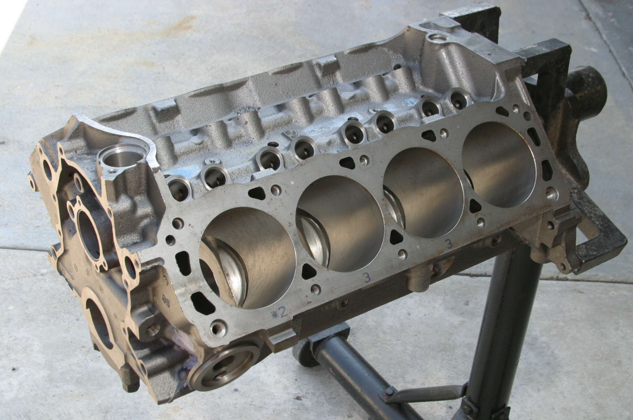
A couple of decades ago, you could snap up a new stock 5.0L block or a Ford Performance Sportsman 5.0L block for chump change to build a completely new small block Ford at prices to be envied today. These blocks are not generally available new anymore, which means you must search for a new old stock block or good used. You may also get the Ford Performance BOSS block (M-6010-BOSS302) as a terrific foundation for your engine building project if you’re planning big power later.
Our vision for this effort was to build a solid reliable 302-based engine that would make 350 to 400 hp with iron heads with potential for 100 more using Trick Flow heads. We envisioned the perfect Mustang power package that could crack the quarter mile in 11-12 seconds at 110-120 mph yet be docile enough for the street on 91 or 93 octane pump gas. Because aftermarket cylinder heads are also a great investment, they are often a better idea than reworking stock iron heads with expensive port work and a valve job.
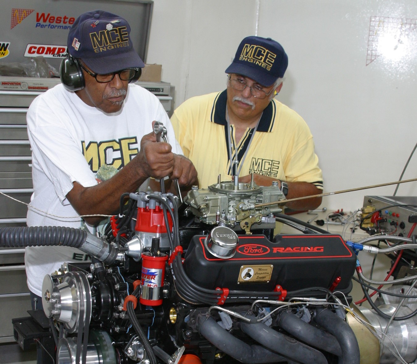
The late Marvin McAfee of MCE Engines in Los Angeles built a number of powerful 347ci stroker engines in his time. He was quick to tell us he liked the 331ci stroker due to its conservative stroke, well within the confines of the 302/5.0L Ford block. He always turned his attentions to Summit Racing Equipment, Comp Cams, Probe Industries, PowerHeads, Edelbrock, MSD Ignition, and Holley for inspiration. His goal for this 331ci stroker was 400 horsepower and 400 lbs.-ft. of torque with potential for more.
Conservative?
Perhaps…Marvin always chose durability over power. His belief was simple—what good is all the power in the world if you blow it up? His agenda always leaned toward durability and conservative power. He wanted to build a powerful 331ci street engine long on durability without having to take out a second mortgage. He added if you are building an engine with the intent of making more power, invest in a good strong bottom end you can grow into.
Good Housekeeping
Strict attention to detail virtually eliminates any risk of engine failure.
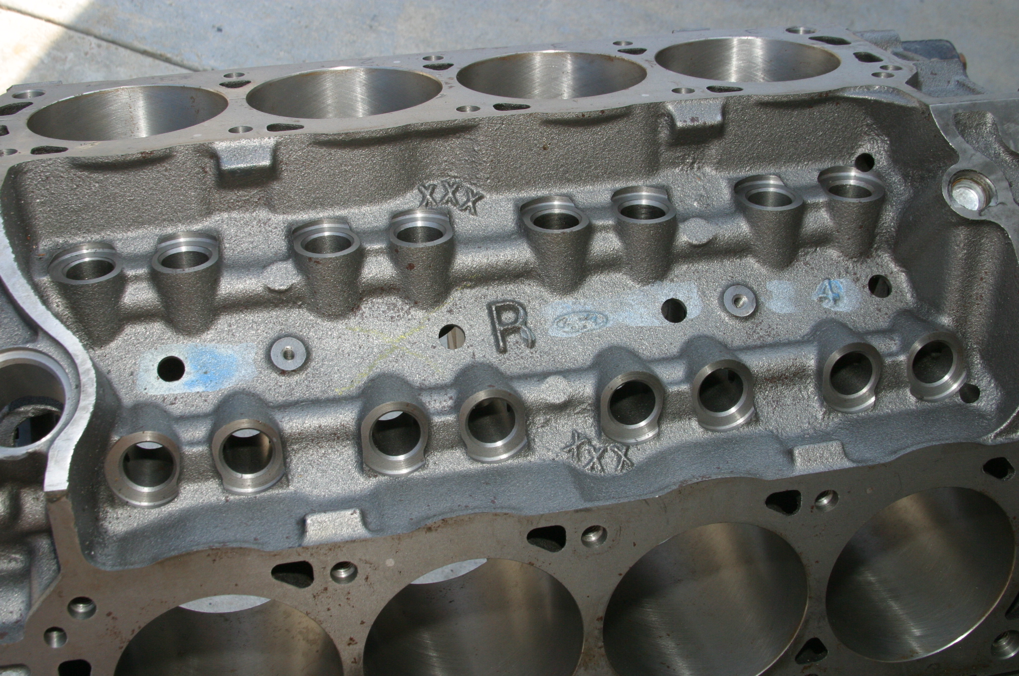
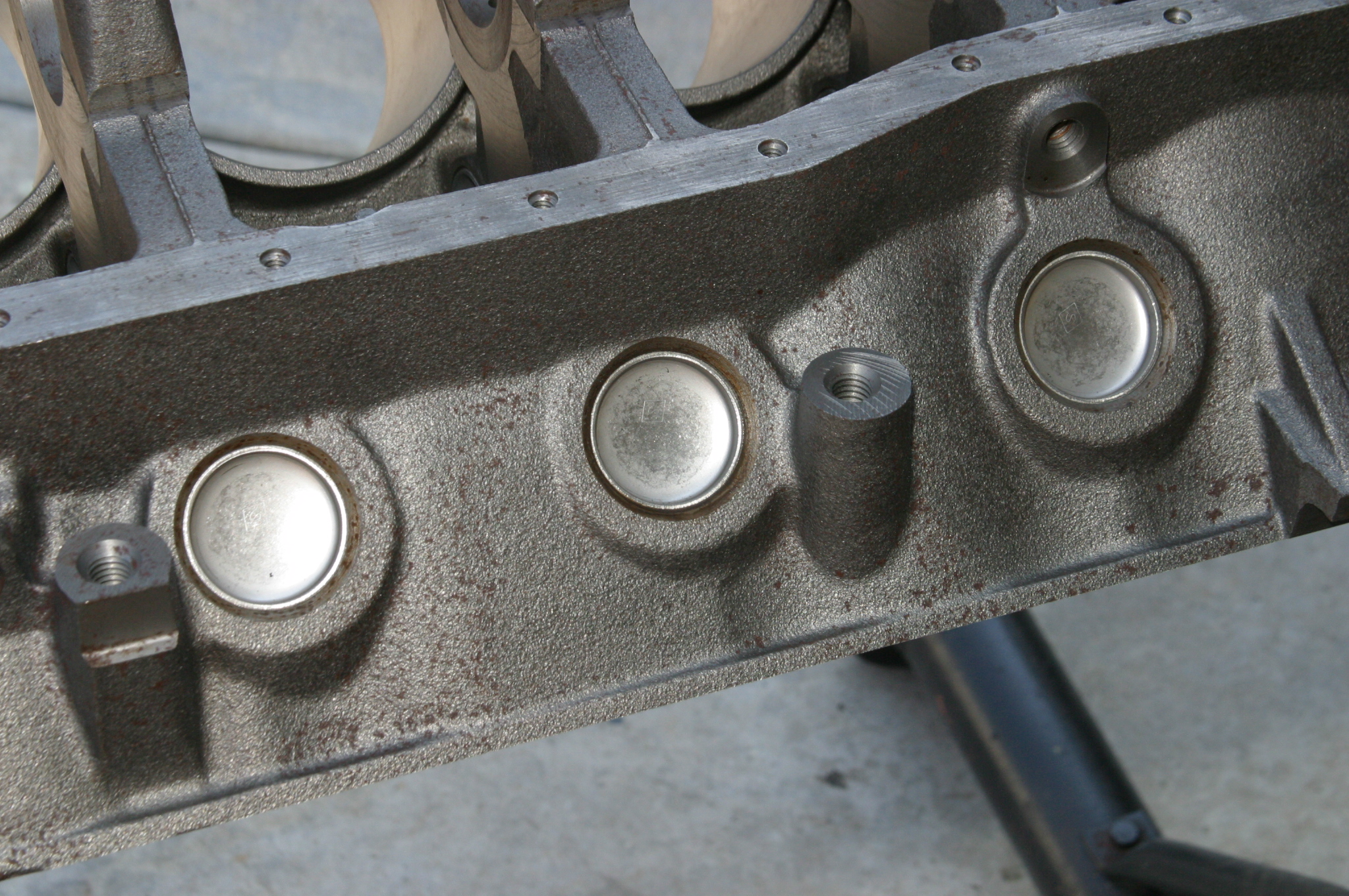
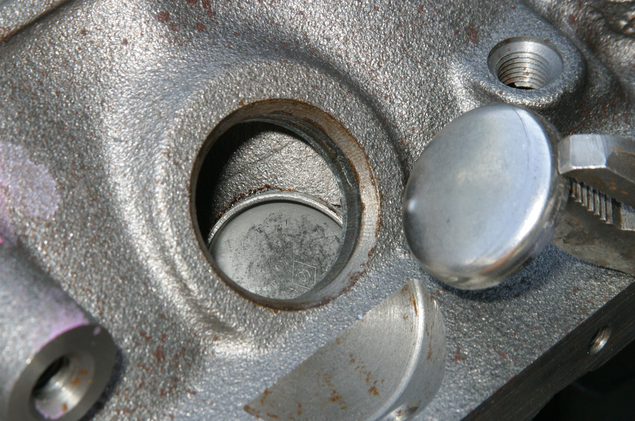
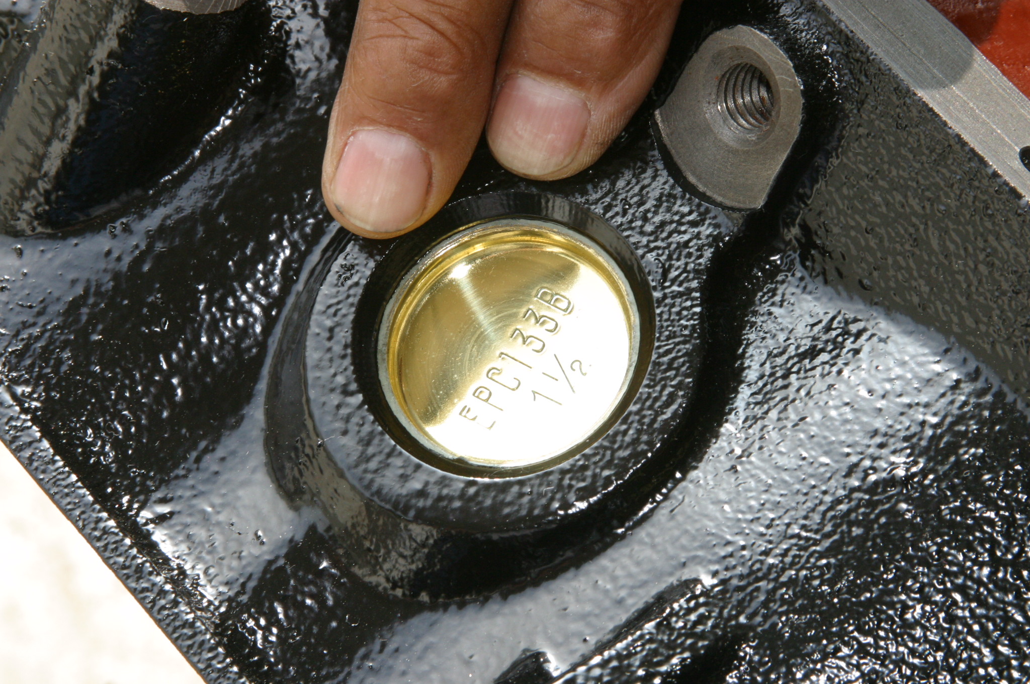
* Remove all the freeze and oil galley plugs
* Remove cam bearings
* Three-Step thermo clean the block and head castings
* Inspect for core shift by examining the lifter bores. If you see bore offset, don’t use the block for a performance build
* Magnaflux the block for cracks
* Deburr all sharp edges in the block and head castings
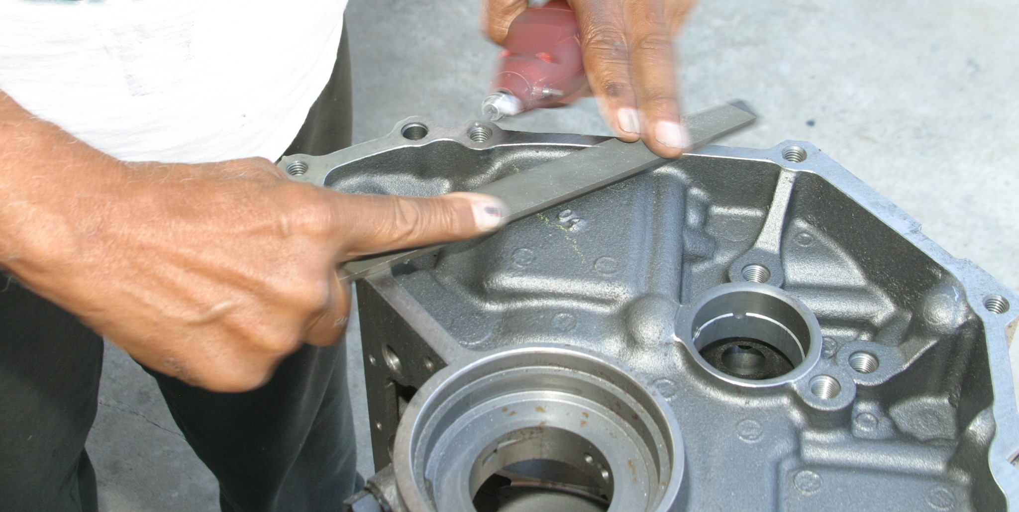
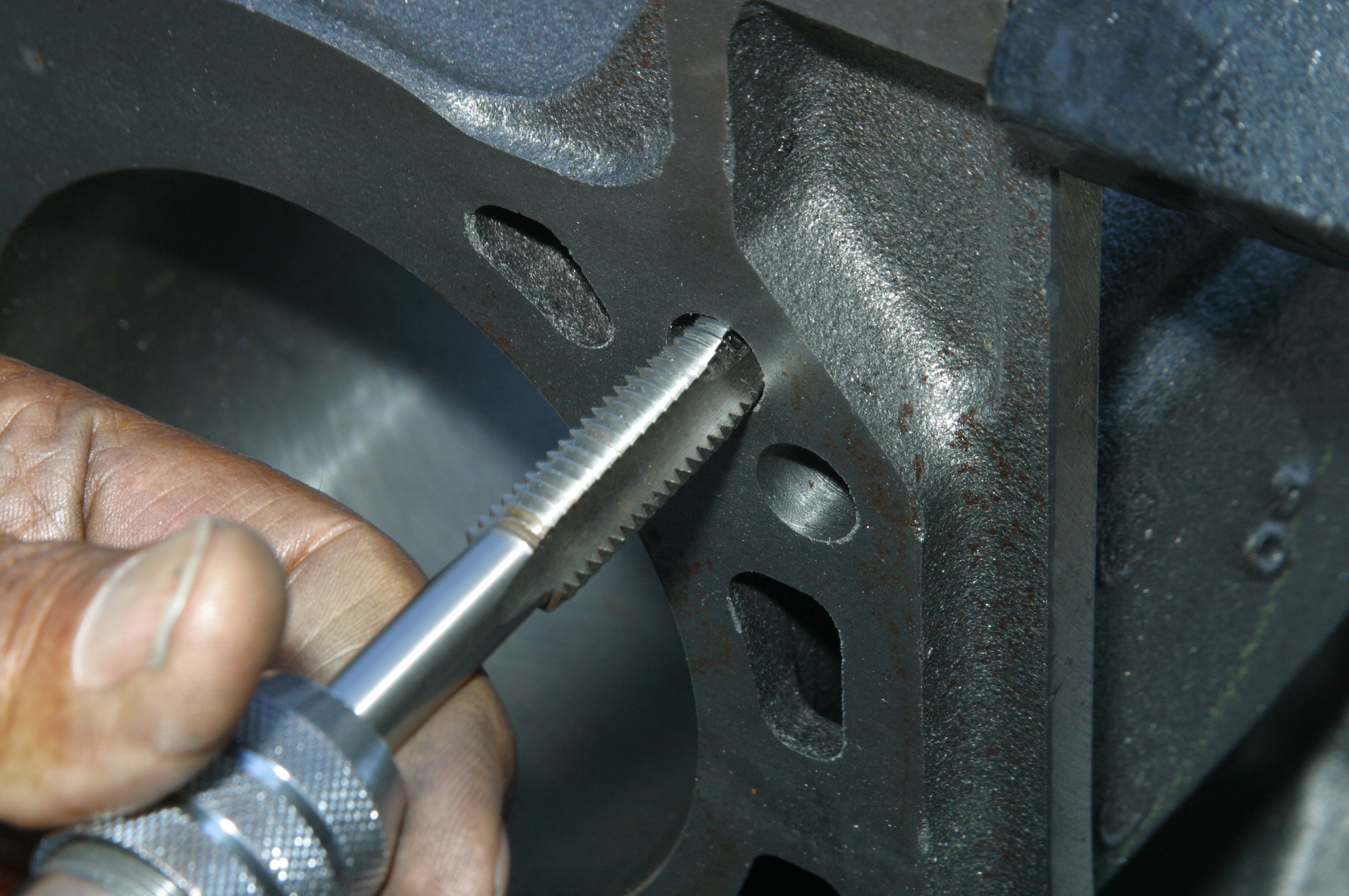
* Tap all oil galley plug holes for screw-in galley plugs
* Radius lifter valley oil drain holes for improved drain back
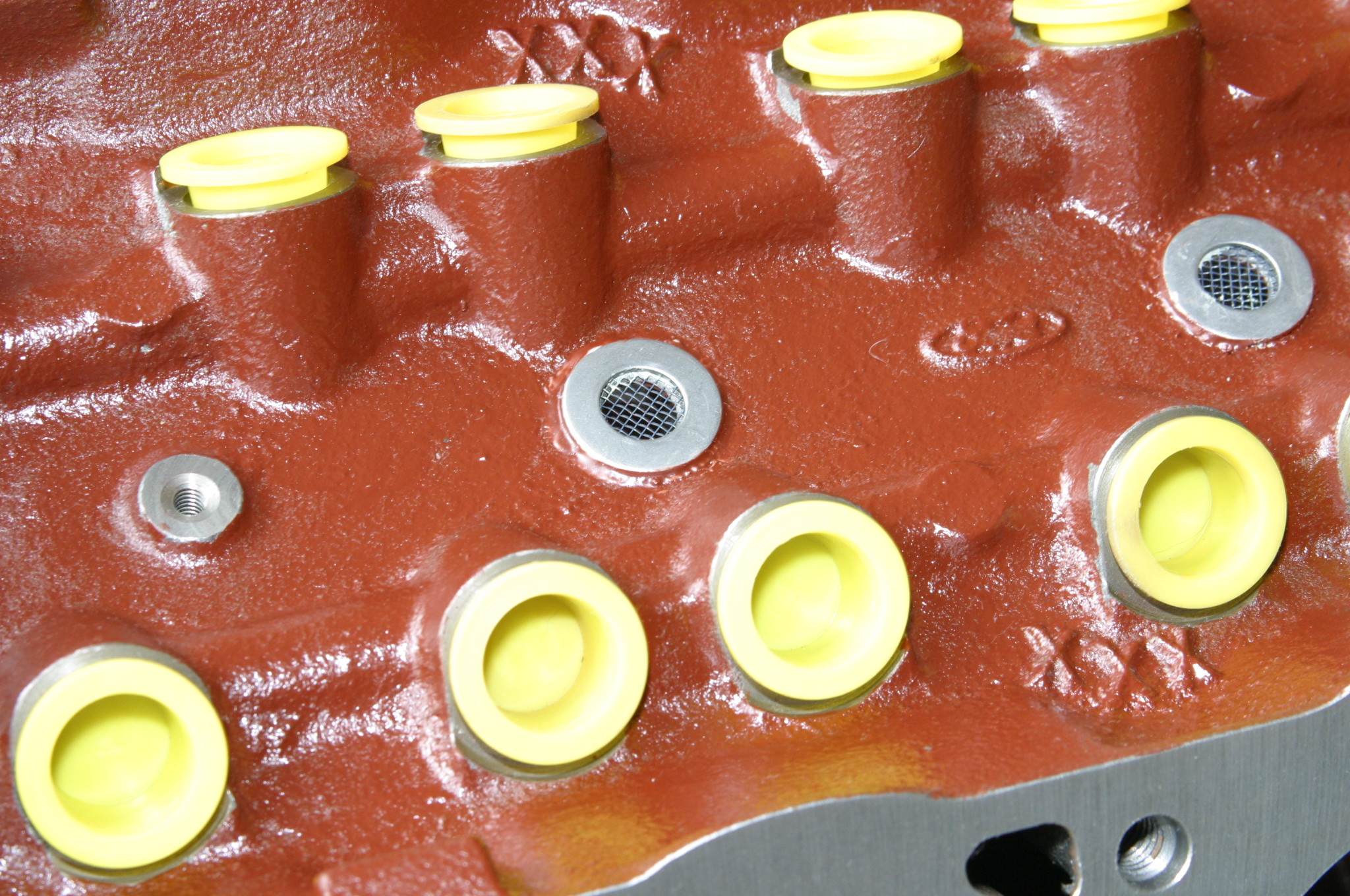
* Install oil drain-back screens in the valley and heads to capture debris
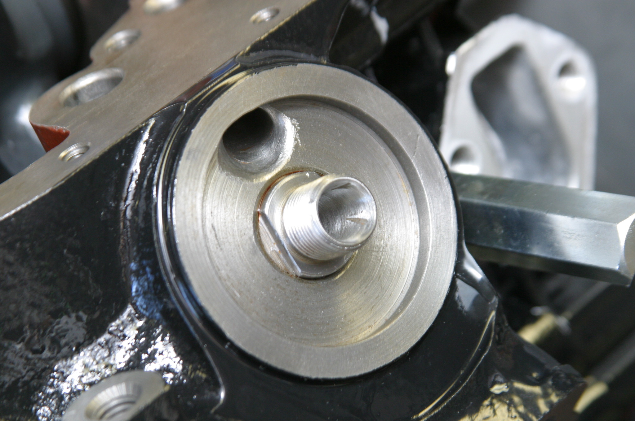
* Chamfer the oil filter adaptor passages for improved flow
* Chase all the bolt-hole threads
* Chamfer and radius all bolt holes for smooth bolt installation
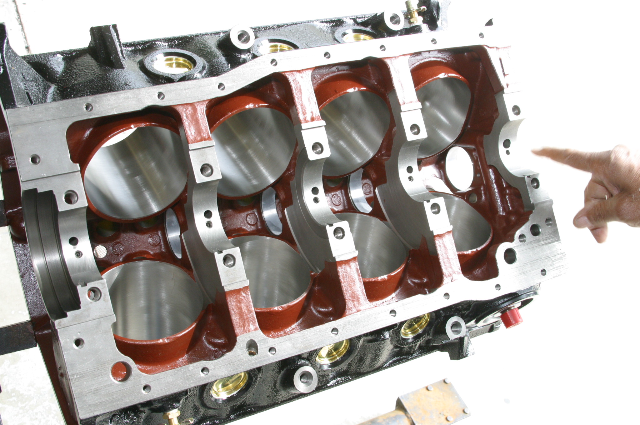
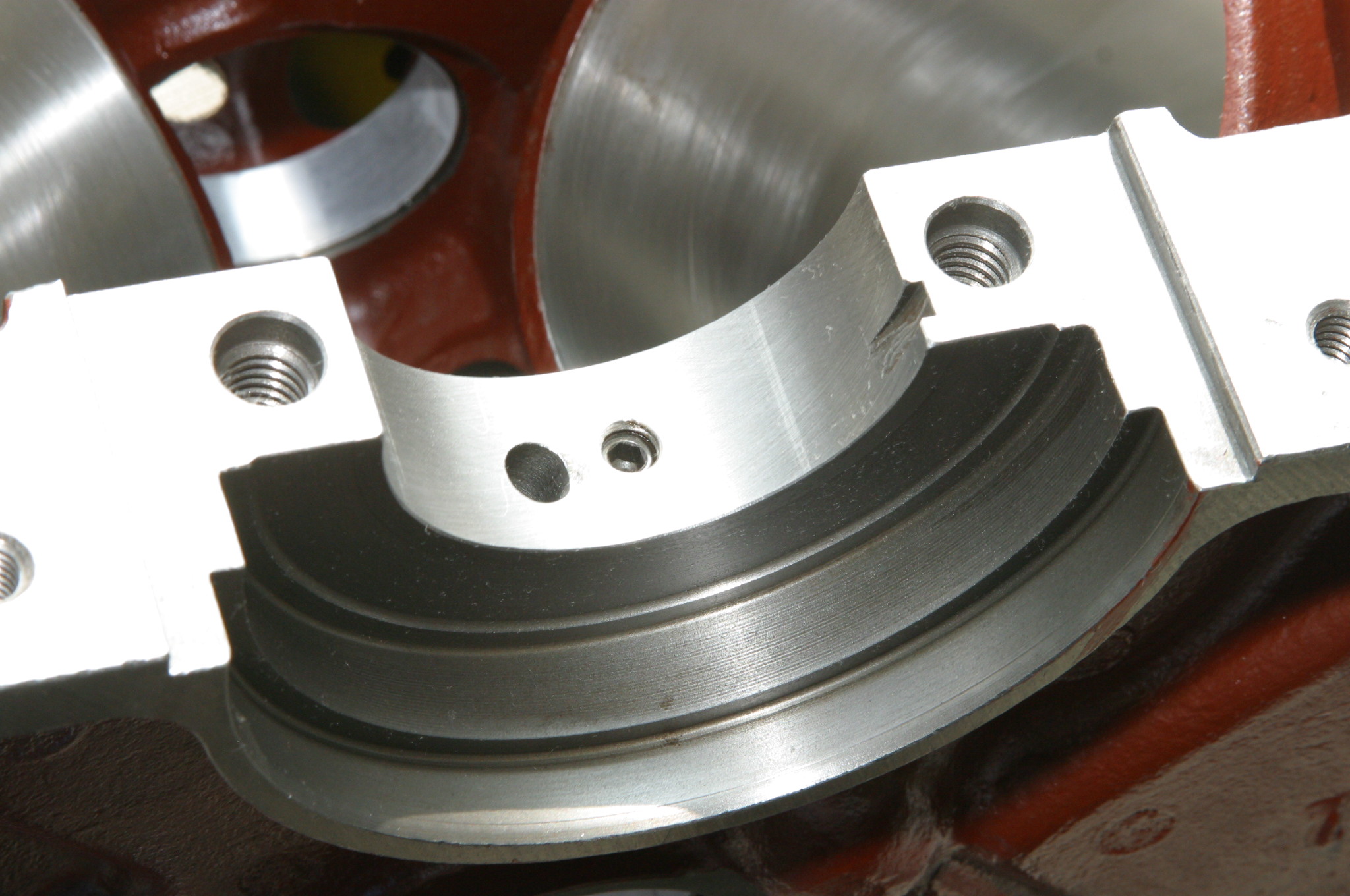
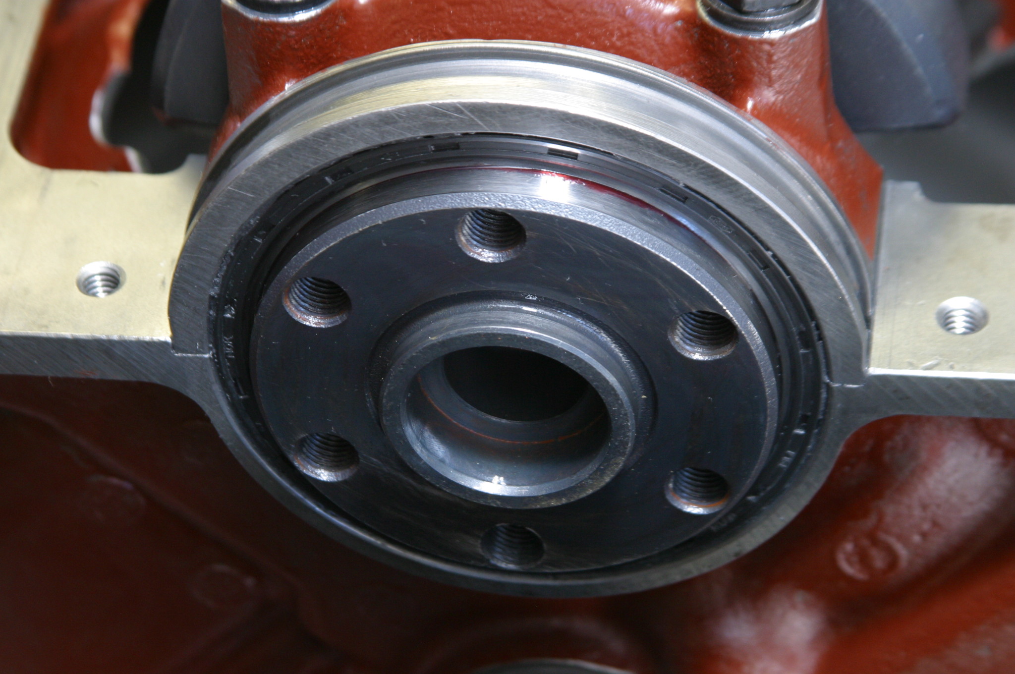
* Mill block decks to true (parallel to each other and flat within 0.002 inch in any 6 inch direction, and an equal distance to the crankshaft centerline)
* Install main caps and torque to specifications for a snug fit
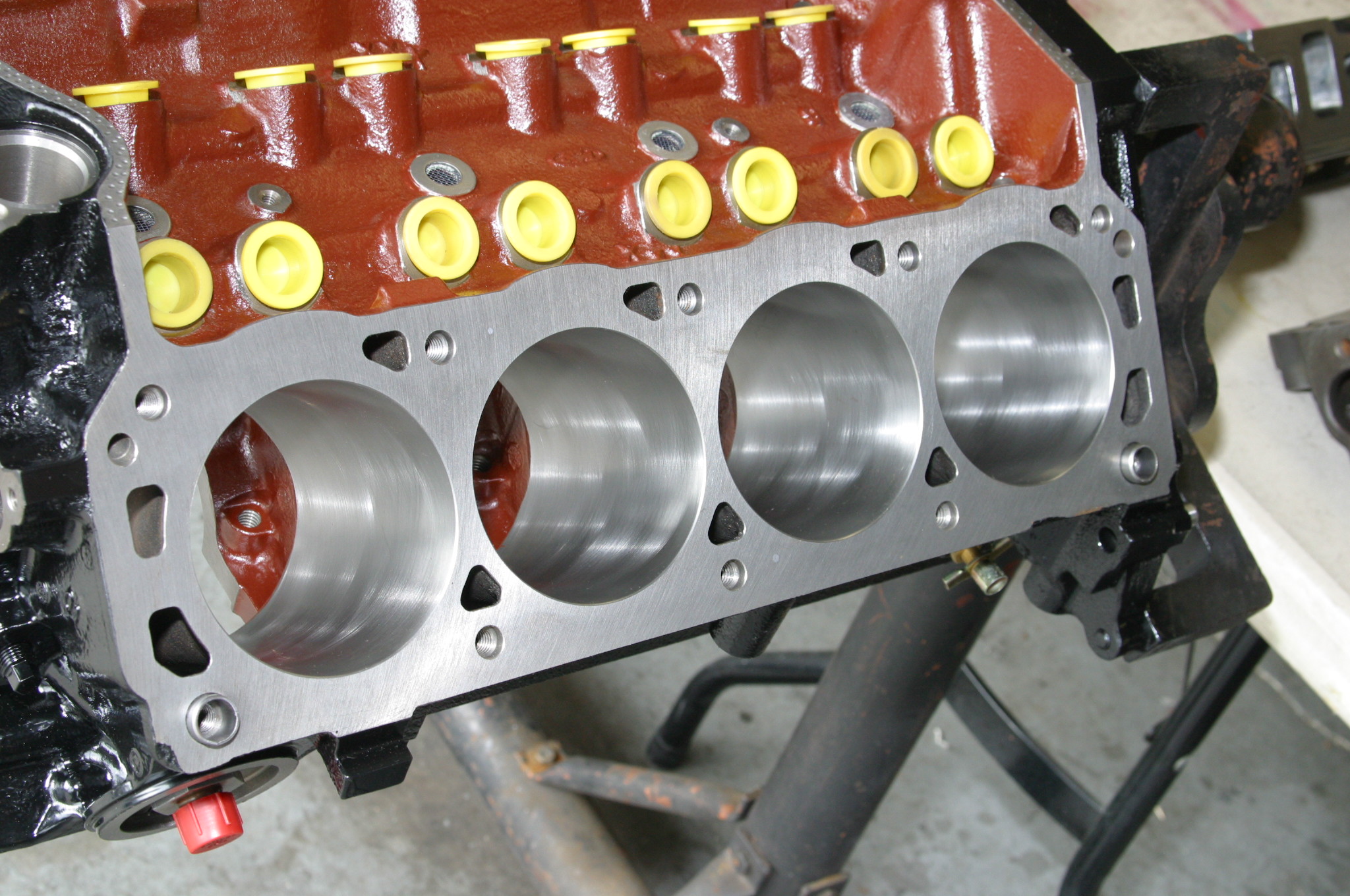
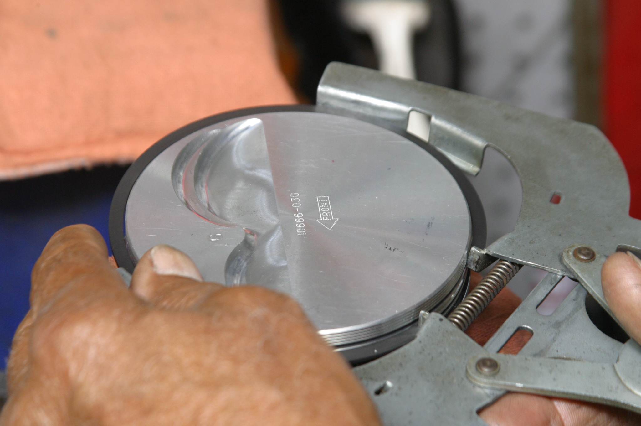
* Bore the cylinders to 4.025 inches, then finish-hone to micro-smooth at 4.030 inches
* Use torque plates during the honing process
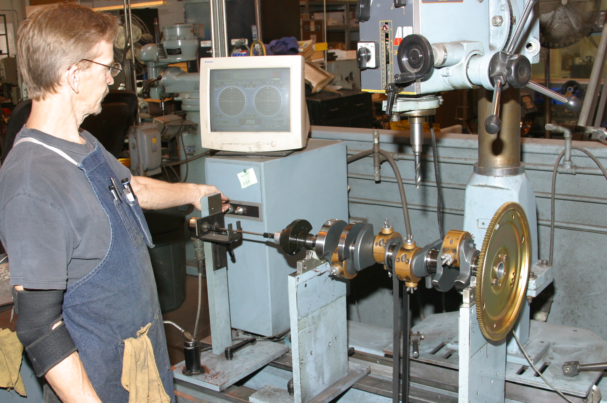
* Align Hone main bearing saddles
* Clean all passages using mineral spirits, bore brushes, and compressed air
* Pre-fit the camshaft and check for smooth rotation (any binding or resistance to rotation indicates bearing misalignment)
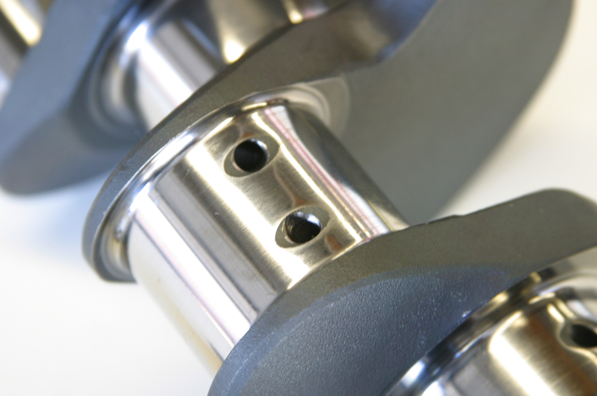
* Drill the righthand oil galley plug 0.020 inch for timing chain lubrication, then install this plug
* Coat all internal cast surfaces with an oil/acid-resistant paint, such as GE’s Glyptal 1201
* Dimple intake manifold end rails with a center punch, both manifold and block, to secure end gaskets
Stealthy Formula For Success
Marvin stressed producing horsepower isn’t magic. Take torque and rpm, multiply these numbers together, and then divide it by 5,252 (5,252 rpm) where they cross. If you’re going to perform on the racetrack, more horsepower is mandatory. On the street, brute horsepower is unnecessary. You need torque on the street to get real respect.
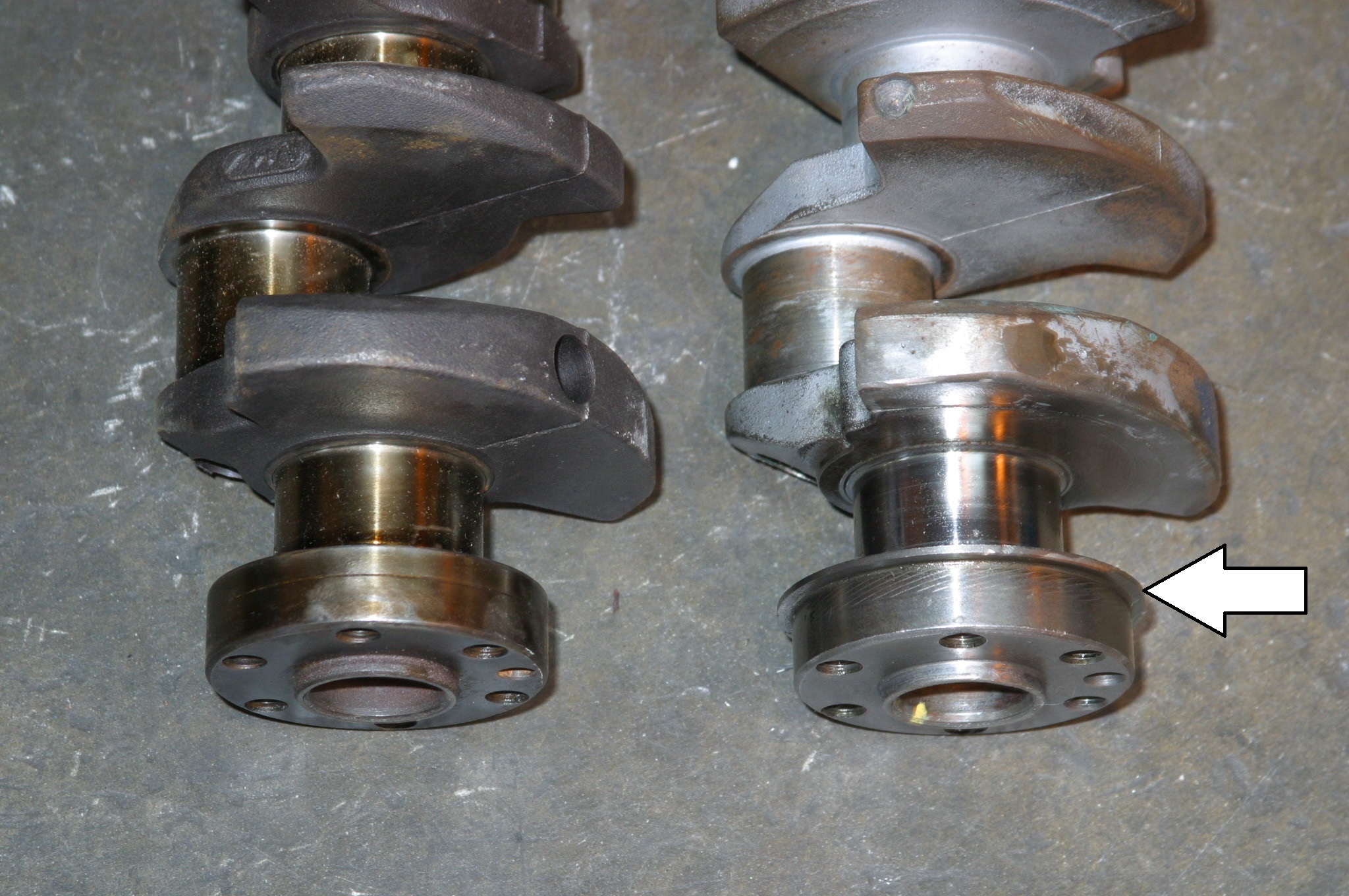
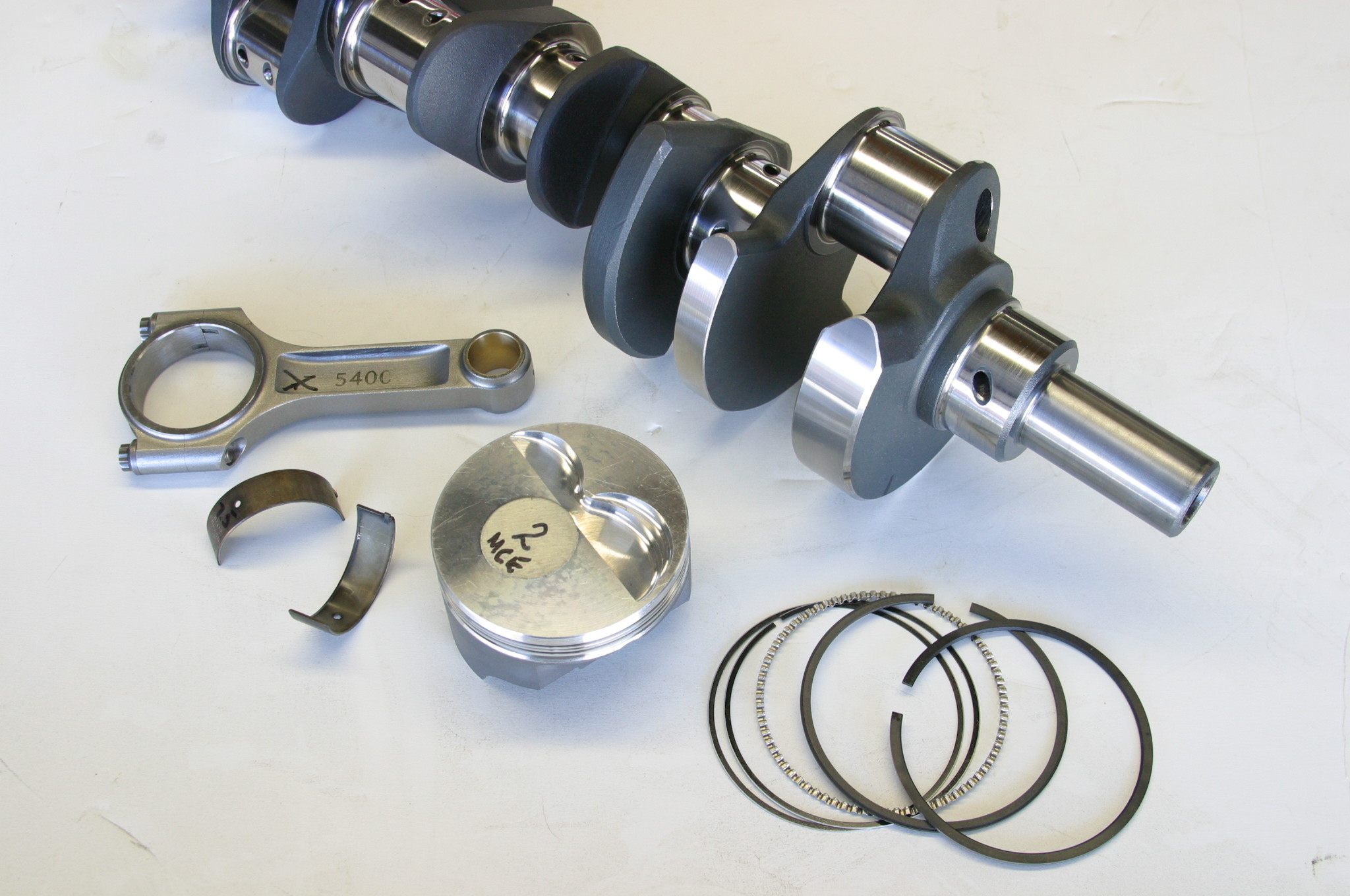
Marvin would tell us back in the day there were two approaches to making 400 horsepower and comparable torque. You can make 400/400 from a 289/302-based Ford block with an affordable 331 inch stroker kit and nodular iron crank, I-beam rods, and hypereutectic pistons. However, this is the package’s service ceiling without getting into aftermarket heads.
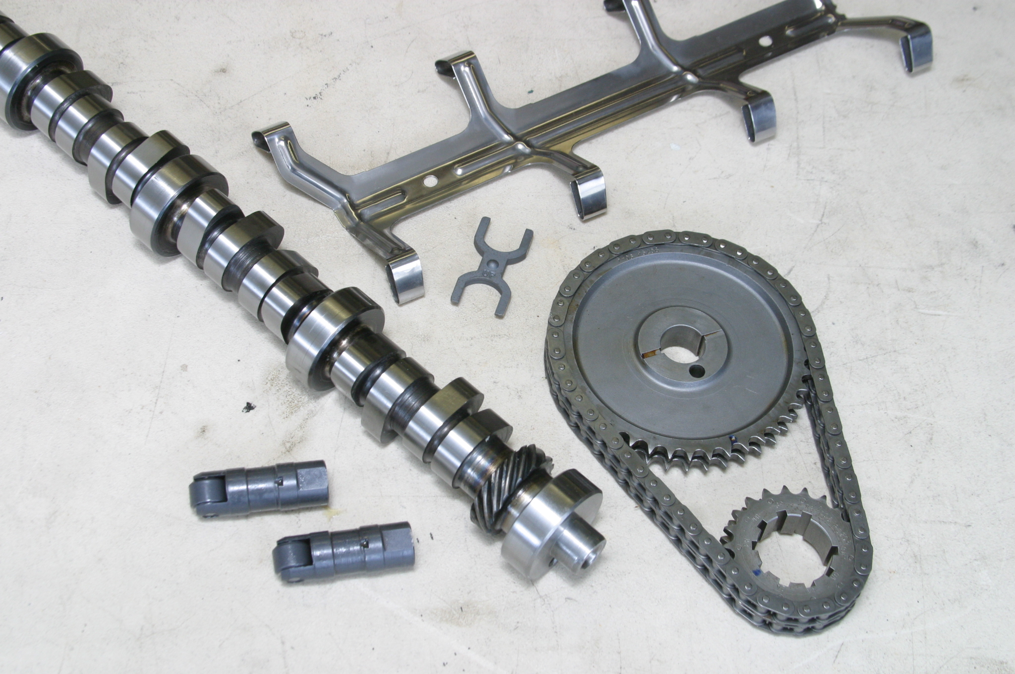
Cylinder Heads, Cam and Valvetrain
* Vintage Ford 1970 302 two-barrel castings (D0AE or D0OE castings)
* 1.94/1.60 inch valves
* Bronze guides
* Hardened exhaust valve seats
* CNC-ported followed by hand porting for improvements in airflow
* GE Glyptal 1201 coating inside
* COMP Cams 1.7:1 roller rocker arms and guide plates
* ARP rocker arm studs
* COMP Cams one-piece push rods
* COMP CCA-35-320-8 camshaft, grind number FW XE264HR-12
* Gross valve lift: 0.544 intake, 0.544 inch exhaust
* Duration at 0.006 inch: 264 intake, 270 exhaust
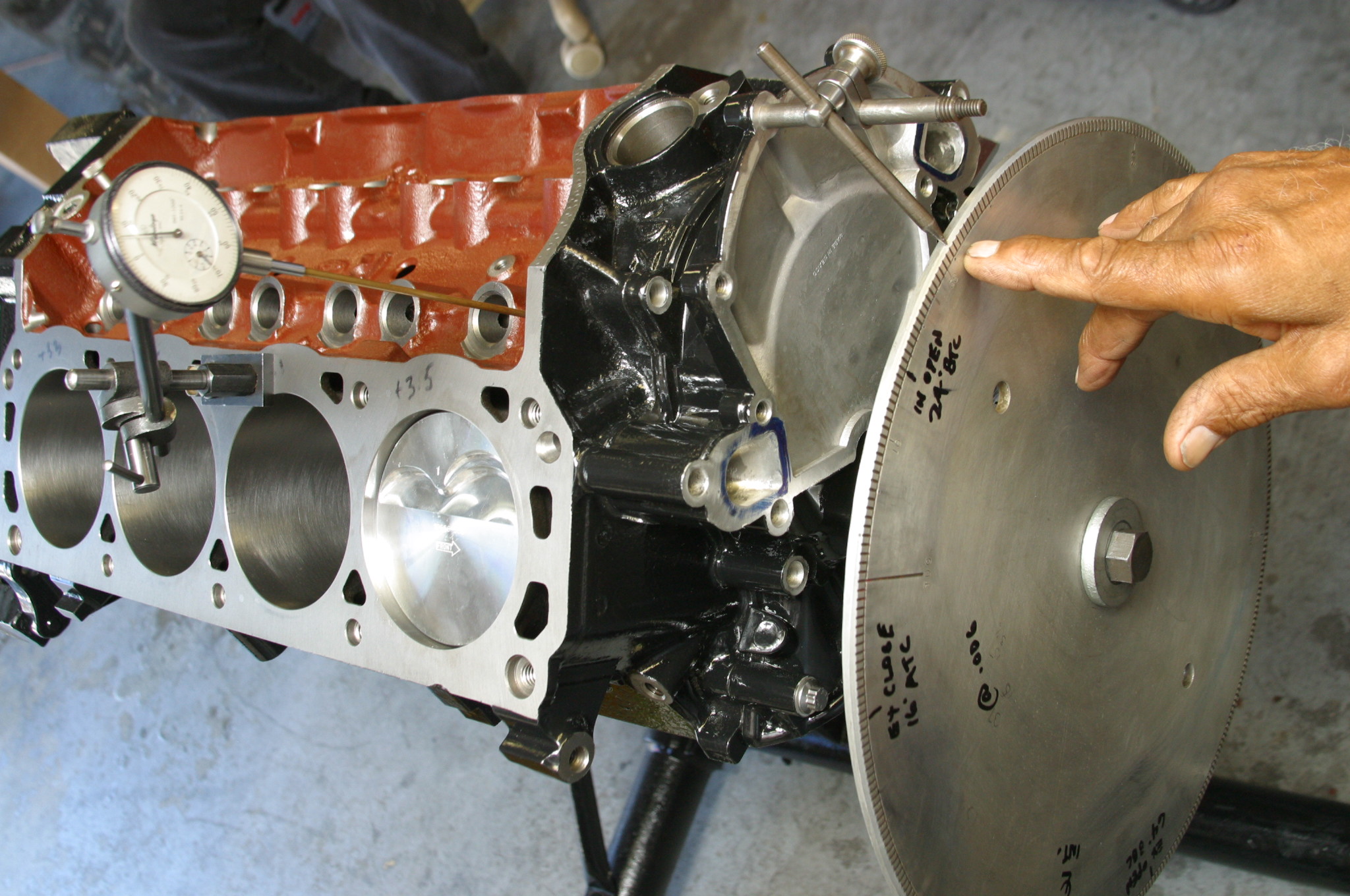
* Valve timing at 0.006 inch: 24 BTDC intake (open), 60 ABDC (closed); 71 BBDC exhaust (open), 19 ATDC (closed)
* 108 degree intake center angle
* Duration at 0.050 inch: 212 intake, 218 exhaust
* Lobe lift: 0.32 inch intake, .032 inch exhaust
* 112 degree lobe separation with a 43 degree valve overlap
* Recommended COMP Cams valve springs: CCA-986-16
Budget 400/400 Street Power
If aftermarket heads are not in the cards, you can make 400/400 by porting stock iron castings. For our build, we opted for PowerHeads for a CNC-port job, along with a five-angle valve job that included hardened exhaust valve seats, new guides, and new stainless steel 1.94/1.60 inch valves. It appears PowerHeads is no longer in business, yet there are plenty of good head porting shops that can get more power from your head castings. Begin with the best small block Ford head castings, which were cast prior to the 1968 model year. You want the smaller 53-57cc kidney bean chambers for the best quench and higher compression ratios. The heads used for this project were 1970-74 vintage with larger 64cc chambers, which were not our best option, but all PowerHeads had at the time.
We opted for a COMP Cams hydraulic roller with 0.544 inch lift and enough duration, 212 intake, 218 exhaust at 0.050 inch lift, with a lobe separation of 112 degrees that provides ample low-speed vacuum for power brakes, and other accessories we needed on the street. Our COMP valvetrain system included dual springs with dampers, steel retainers and keepers. We opted for a Milodon dual-roller timing set. COMP’s 1.7:1 ratio roller rockers were also inspected and blueprinted. ARP screw-in rocker-arm studs with guide plates got everything square on top.
Engine Building Technique
* Chase, clean, and inspect all bolts and bolt-hole threads
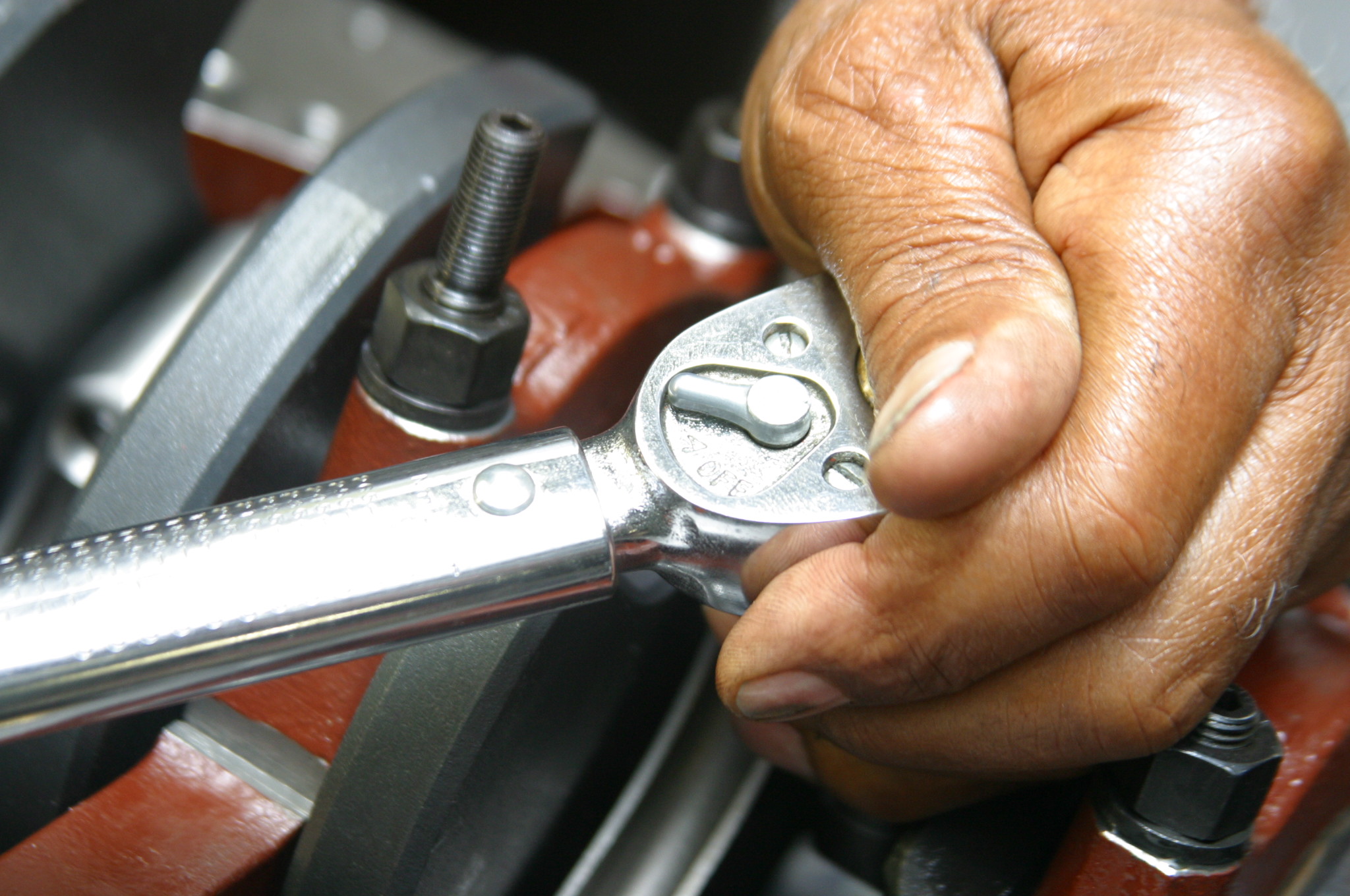
* Lubricate bolt threads before torqueing, never install bolts dry
* Apply assembly lube lightly, as opposed to dripping wet
* Do not use Teflon tape on bolt threads, it will leak—use a thread sealer
* Use high-temp RTV sealer on brass freeze plugs in the block and heads. Do this sparingly on bolt threads where necessary (e.g., wet decks, cylinder heads, screw-in rocker-arm studs, and intake manifolds)
* When using RTV silicone sealer on gaskets, use a thin layer that will not squeeze out. Excess sealer can break free and clog water jackets and radiators
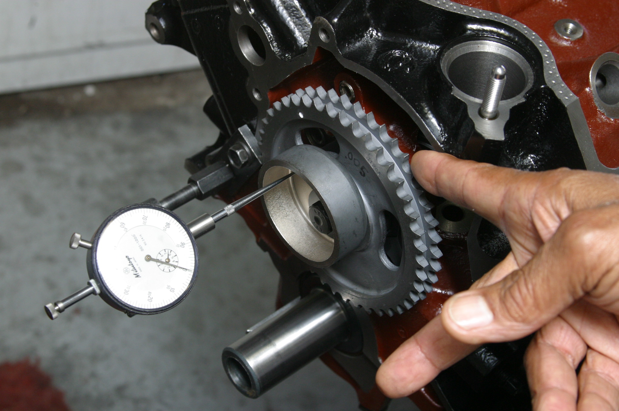
* All engine parts should fit together with a comfortable fit (i.e., a nice, smooth fit with minimal effort). Marvin calls this a zero fit. A timing gear should slide right on the crankshaft or camshaft without effort-not loose and sloppy, just a smooth fit—if you need a hammer, it’s too tight; if it can fall off, it’s too loose
* Piston ring width controls engine friction and temperature. The wider the ring, the greater the friction and heat transfer. Run 5/64 inch width on the street because of long-term wear requirements, and 1/16 inch for racing because there is less long-term wear and friction concerns. Watch ring tension.
* Forged pistons grow more with heat; cast and hypereutectic pistons grow less with heat. This means forged pistons rattle cold
* Use engine assembly lube on main, rod, and cam bearings between the journal and bearing only. No lube between the bearings and block saddles
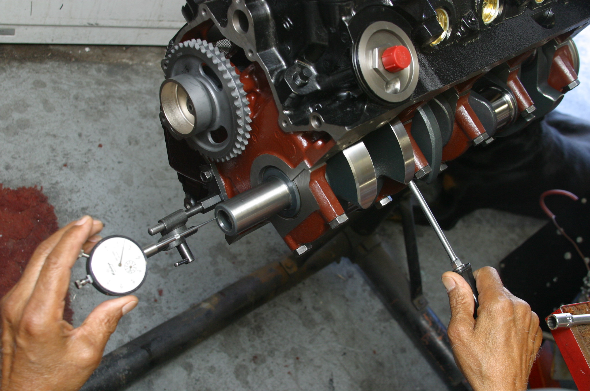
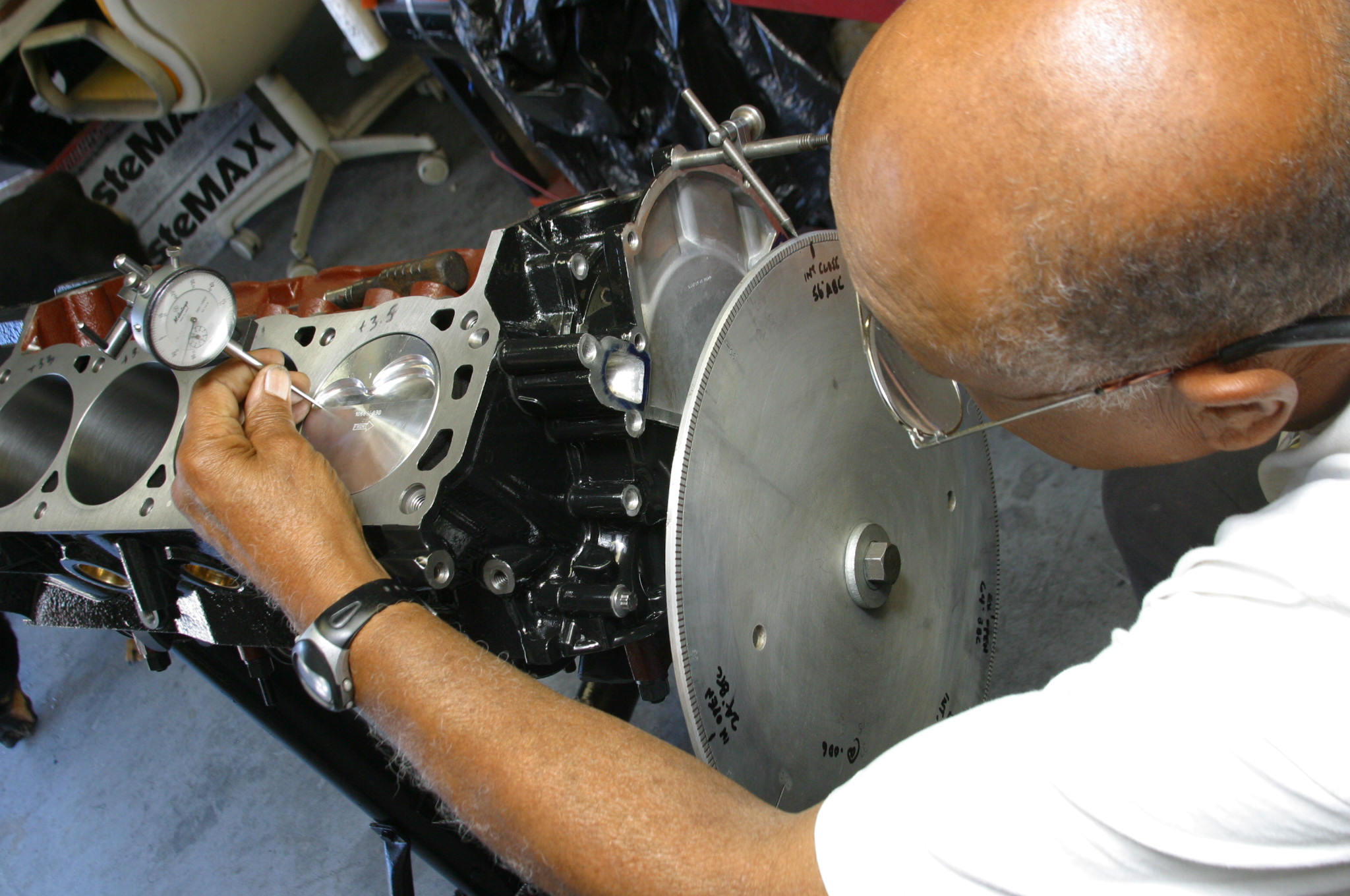
* Do a mockup before assembly: Pre-assemble the long block without the piston rings, and check compression and deck heights as well as piston-to-valve clearances. Check side clearances and end play also. Follow basic engine math and check compression ratio twice. While this takes time, it is necessary for engine building integrity
* Degree the camshaft and check valve-timing events
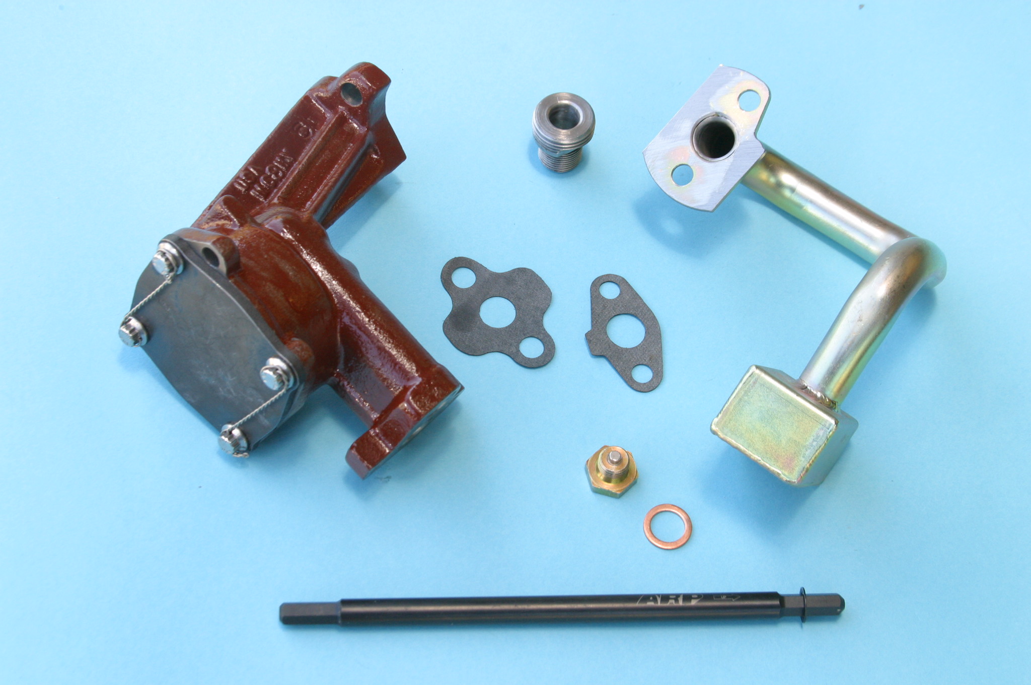
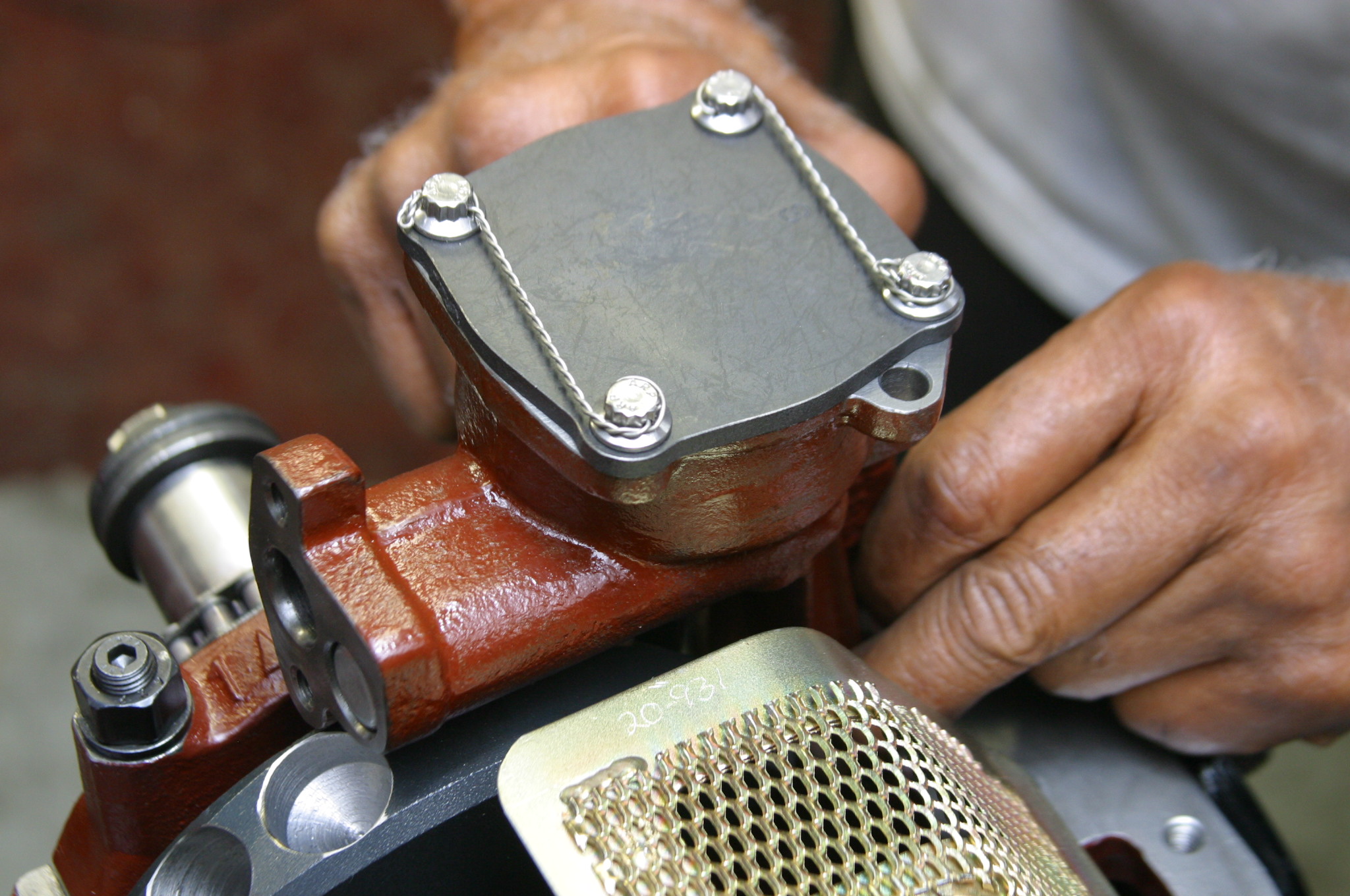
* Blueprint the oil pump, checking rotor side clearances and relief valve for proper operation. Never install an oil pump right out of the box
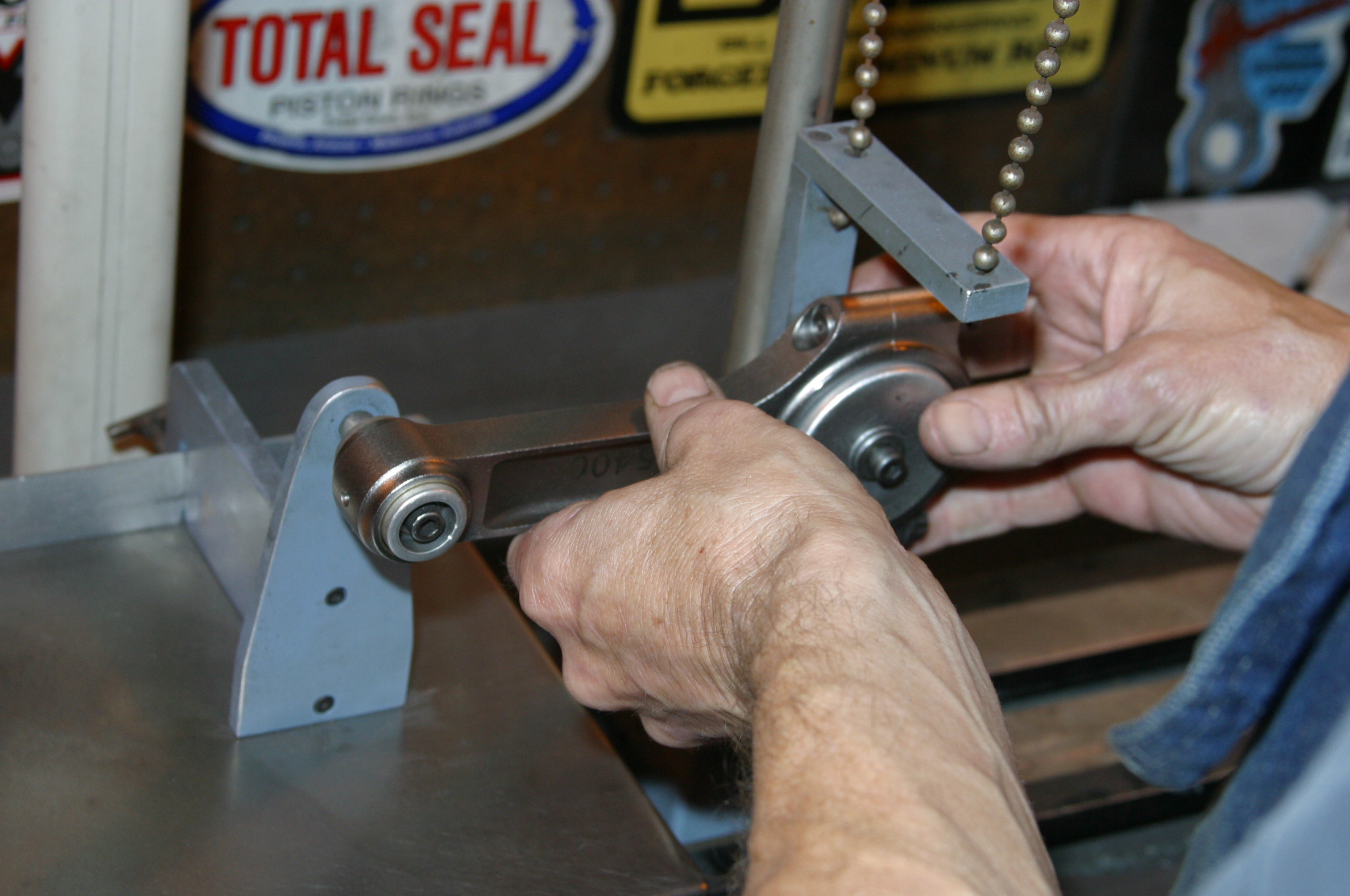
* Always check valvetrain geometry. Rocker arms don’t always line up with valve stems. The rocker arm tip needs to be dead center on the valve stem tip at 50 percent of valve lift
* Apply GE’s Glyptal 1201 to all unmachined iron surfaces for better oil drainback and to keep stray iron particles out of the oil
* Use main bearing cap screw-in studs instead of bolts for added strength
* No exceptions—use Grade 8 fasteners
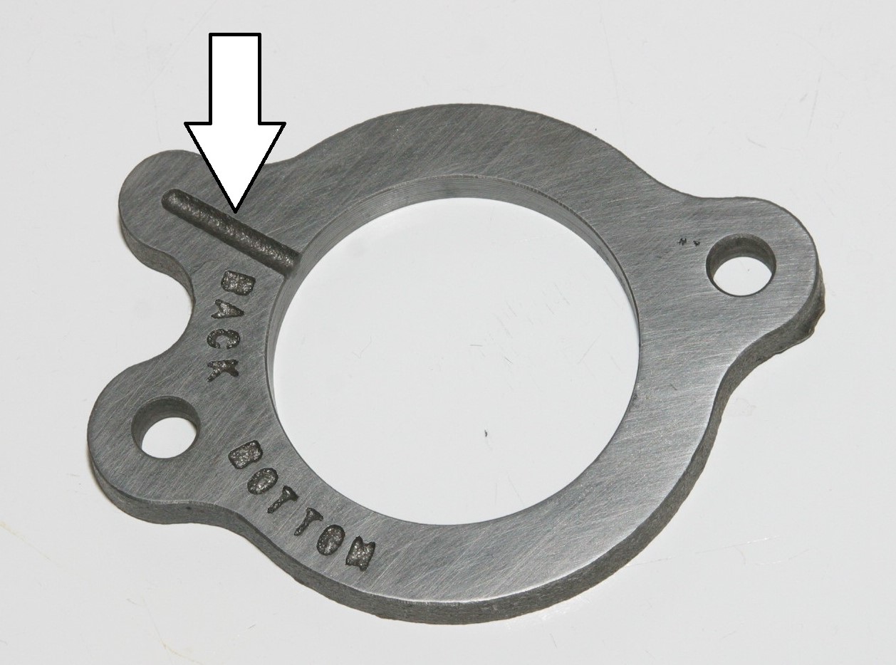
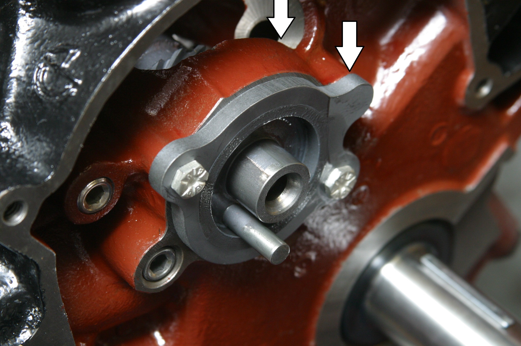
* Ascertain proper head-gasket installation: Gasket end cooling passages always go at the rear of the block
* Dimple the intake gasket end rails for gasket security
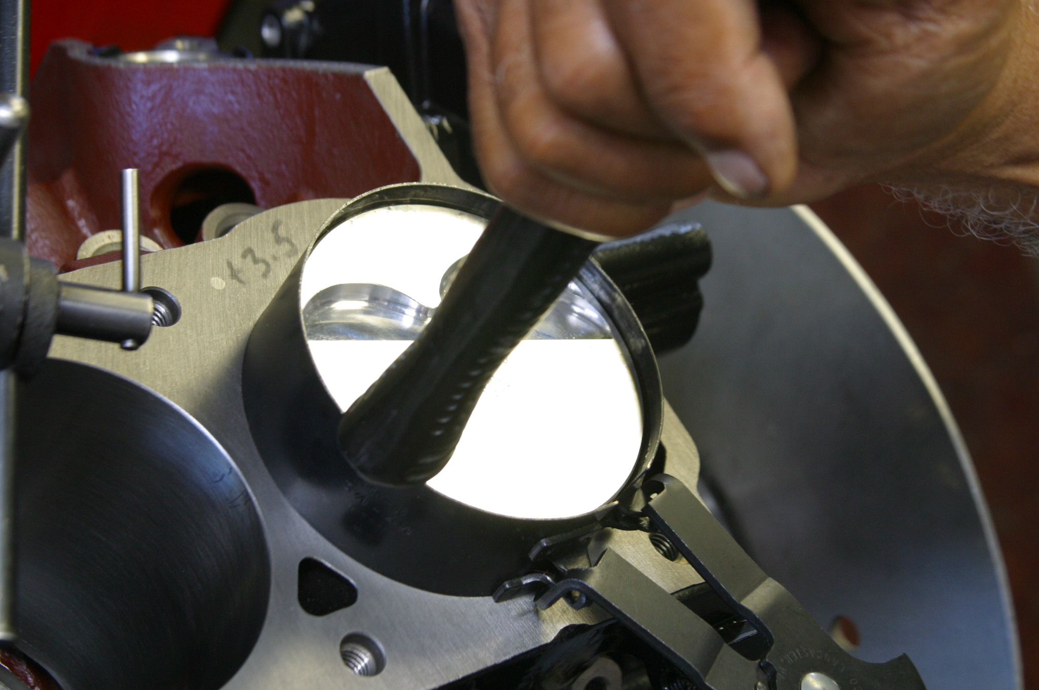
* Do a five-angle valve job for improved airflow
* Valve seat width affects valve temperature. Narrow seat (contact) makes the valve run hotter while wide seats run cooler. A good rule of thumb is 0.040 inch intake and 0.060 inch exhaust for racing, and 0.070 inch intake and 0.100 inch exhaust for street
* Use a magnetic oil drain plug to pick up any stray iron or steel particles
These pesky details may seem like overkill, but when you’re reviewing the remains of a failed engine, it’s little comfort to realize you should have taken care of the details. Detail is of utmost importance in any engine build. Next time in Part 2, we will continue our MCE Engines 331 Stealth build with more details important to engine integrity, reliability, and power.
Then, we’ll get some dyno numbers to prove this thing out.
[…] Last month, we introduced you to the 331ci “Street Stealth” built by MCE Engines. […]