Talk about a stealthy means to displacement and affordable power? The beauty of this restomod approach to power is—no one knows it’s there but you. The time-proven stroker, by its very design, builds in horsepower and torque by increasing displacement and stroke. When you increase stroke, you get increased mechanical advantage—a longer arm—building real horsepower and torque into your engine build.
For nearly the same cost as machine work on your existing rotating stock, you can get into a complete stroker kit that gives you more displacement. Stroker kits don’t have to be expensive either. Budget cast crank (known as cast steel) stroker kits roll in huge amounts of power without you having to sell off the farm. This makes great economic sense when you consider what we once had to do to increase stroke.
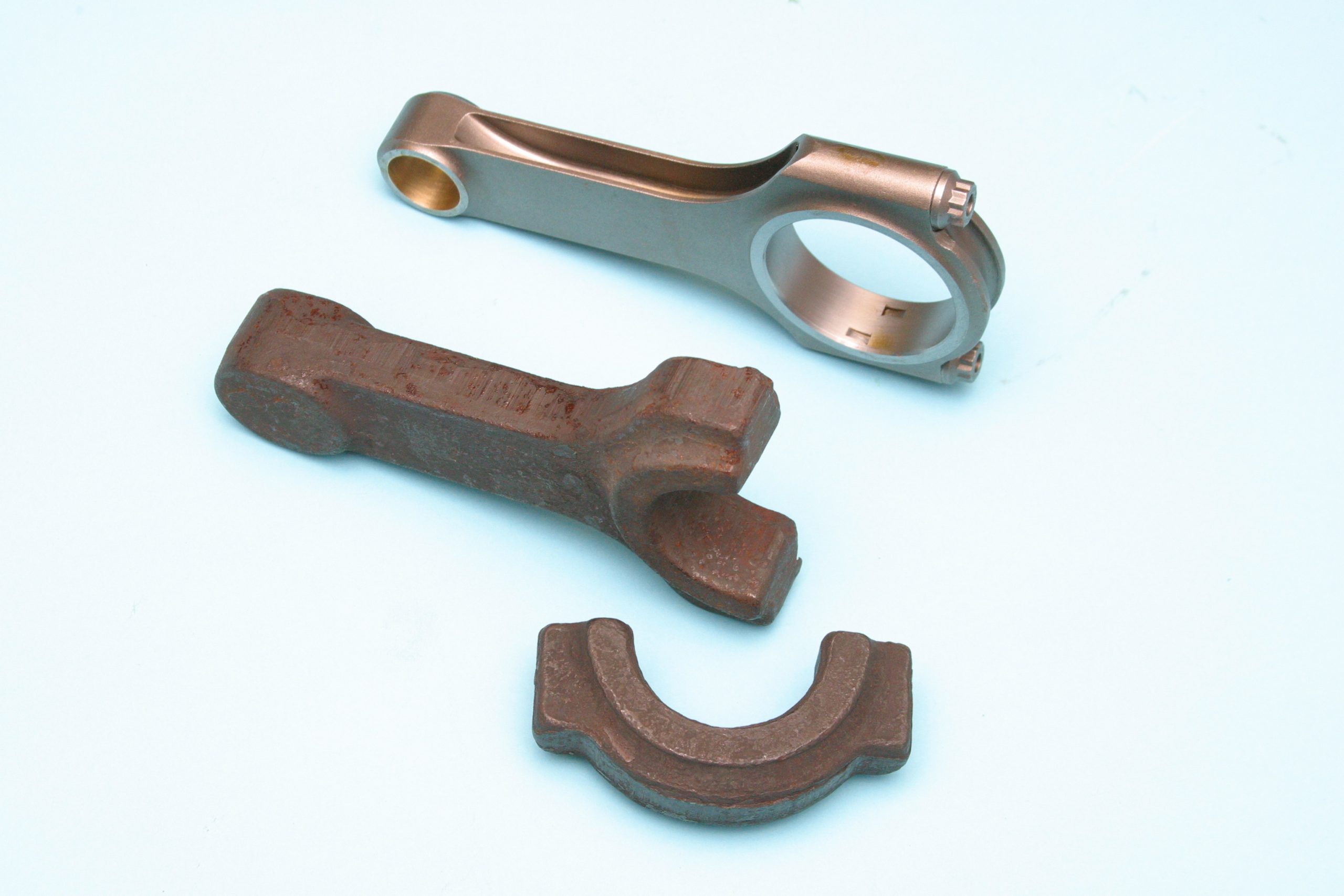
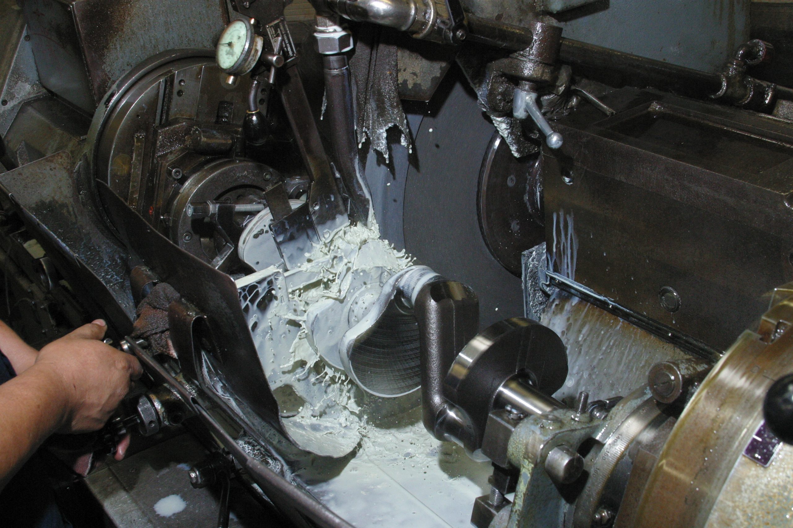
Back in the day, it took a seasoned machine shop to get additional stroke—offset ground crank, the right rods, and custom pistons. It was costly and prohibitive to get into a stroker. SCAT Enterprises pioneered the stroker kit back in the 1960s, inspiring an industry to get in step with this innovative company.
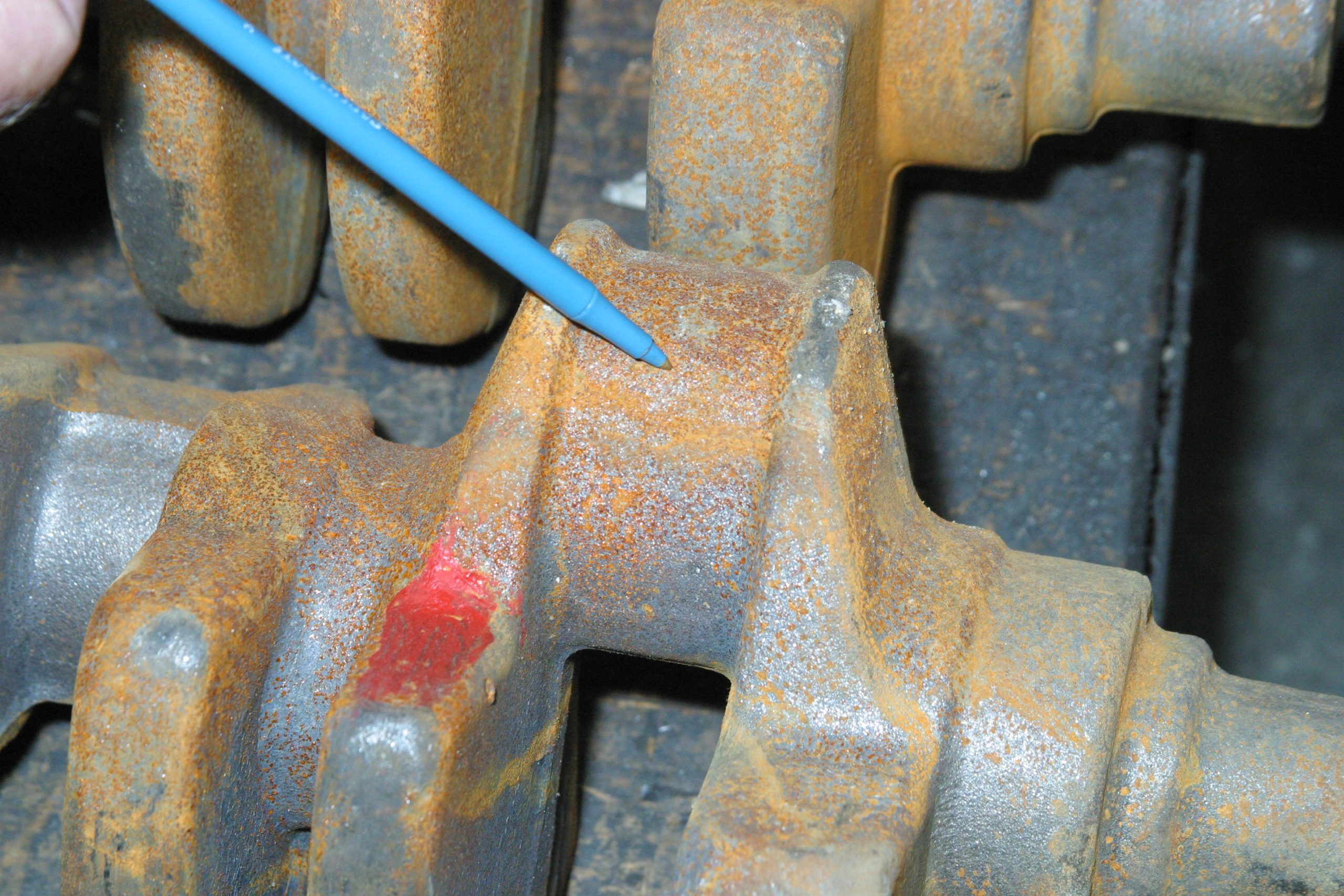
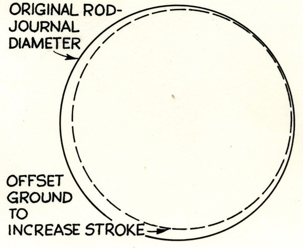
One of the approaches employed to increase stroke with a factory crank was known as offset grinding. Offset grinding the rod journal moves the centerline of the rod journal away from or toward the centerline of the main journal. This, of course, will increase or decrease stroke. By offset grinding the crank, your engine will call for special connecting rods with correctly sized bearing bores to fit the crank.
Scat Enterprise’s founder and president, Tom Lieb, has long understood the need for displacement and power. Lieb began the SCAT legacy out of his parents’ garage in 1964 with a vision. It was Tom’s passion for automobiles, racing, and street power that inspired him to go where few others were going. Of course, stroker engines were nothing new at the time. However, affordable stroker kits and bottom end components for the masses were something Lieb saw a very definite need for. He went to work conceiving affordable stroker kits for hot rodders.
How to Select the Best Engine Stroker Kit
There are basic rules you should follow when you’re considering a stroker kit.
- Opt for as long a connecting rod as possible to reduce frictional losses and increase piston dwell time.
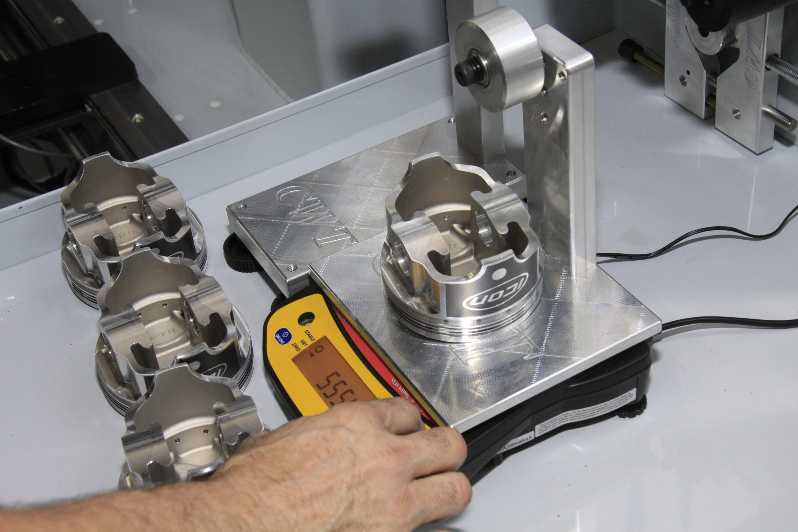
- Shop for the lightest reciprocating components available, which frees up power and reduces wear.
- Be realistic about what you can afford and need.
Choose the highest compression ratio possible while avoiding detonation issues. Go with cylinder heads with the largest valves and ports possible for improved breathing. You’re going to want a good high-swirl wedge chamber with good quench. When it comes to selecting the best camshaft for your stroker, you may want to talk with Summit Racing’s tech staff. Increase valve size and lift proportional to the increased displacement. You may be building a Chevy 350, but the displacement is no longer 350ci. When you grow it to 383 or 408ci, the infrastructure must be there to support the increased displacement.
Induction and exhaust systems should accommodate the increased displacement. Ascertain the induction system has enough flow capacity to make good use of the increased displacement. The cooler you can keep induction, the better your engine will be in terms of power and efficiency. You want the intake charge to be as cool as possible, which makes the best use of air molecules dancing more closely together, which helps the rate of expansion. The message here is infrastructure. You want a support system that can handle the increase in displacement.
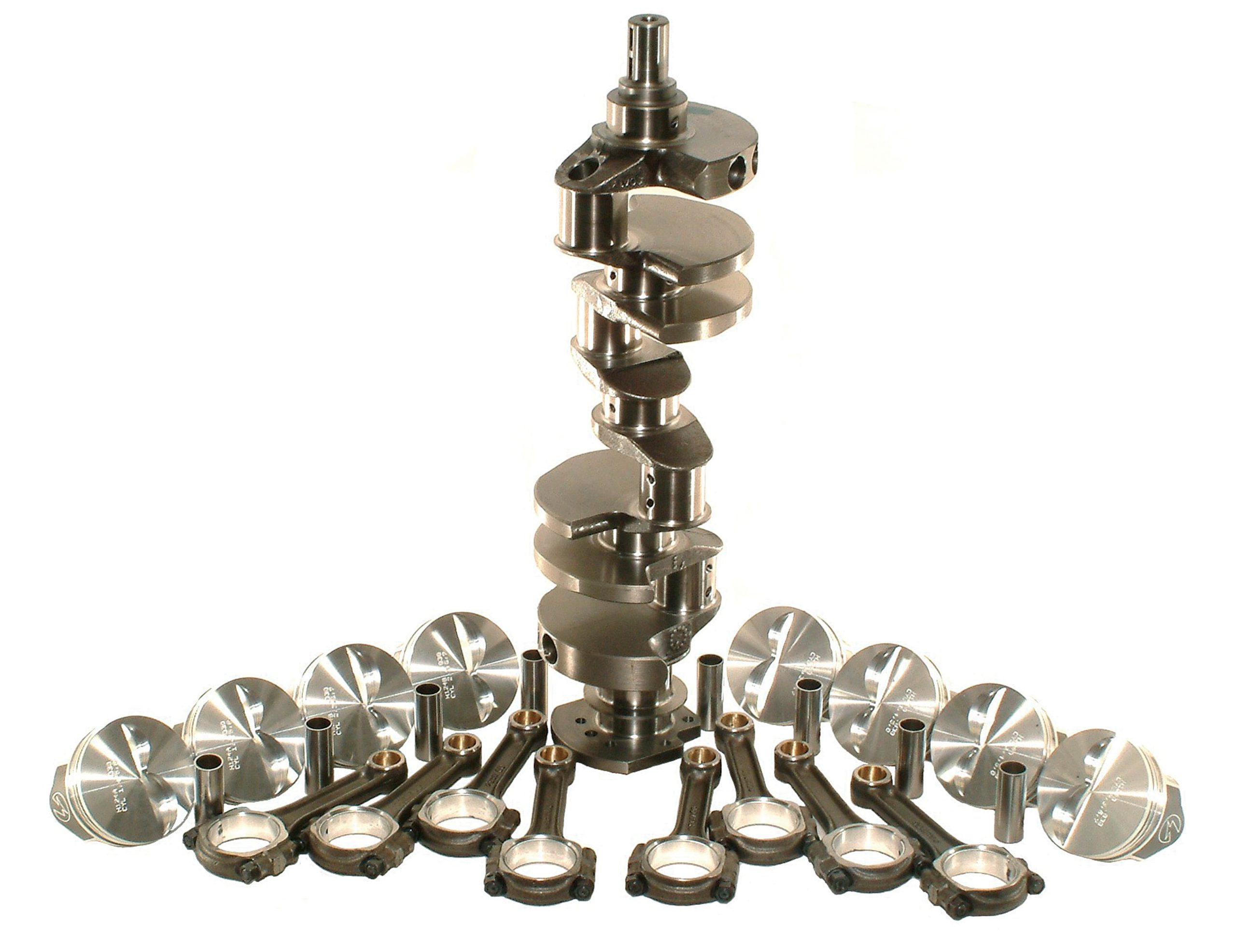
A Stroker Kit’s Contents
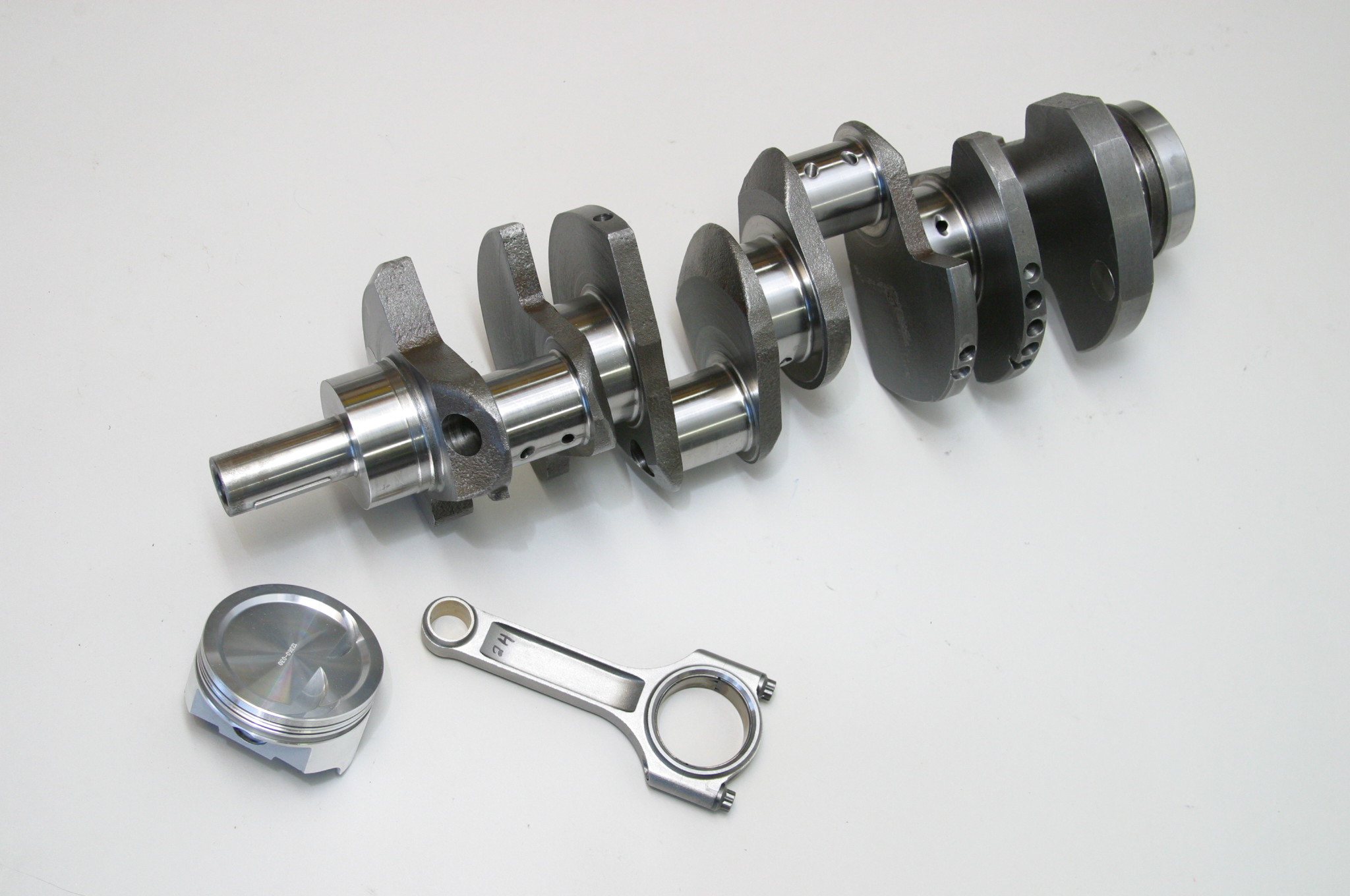
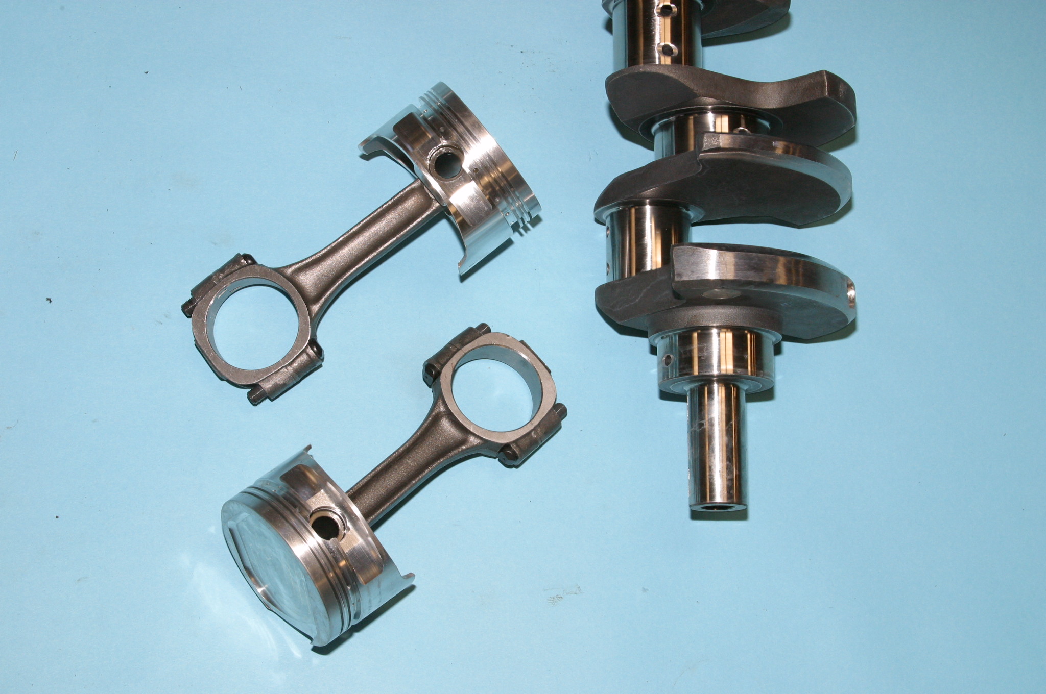
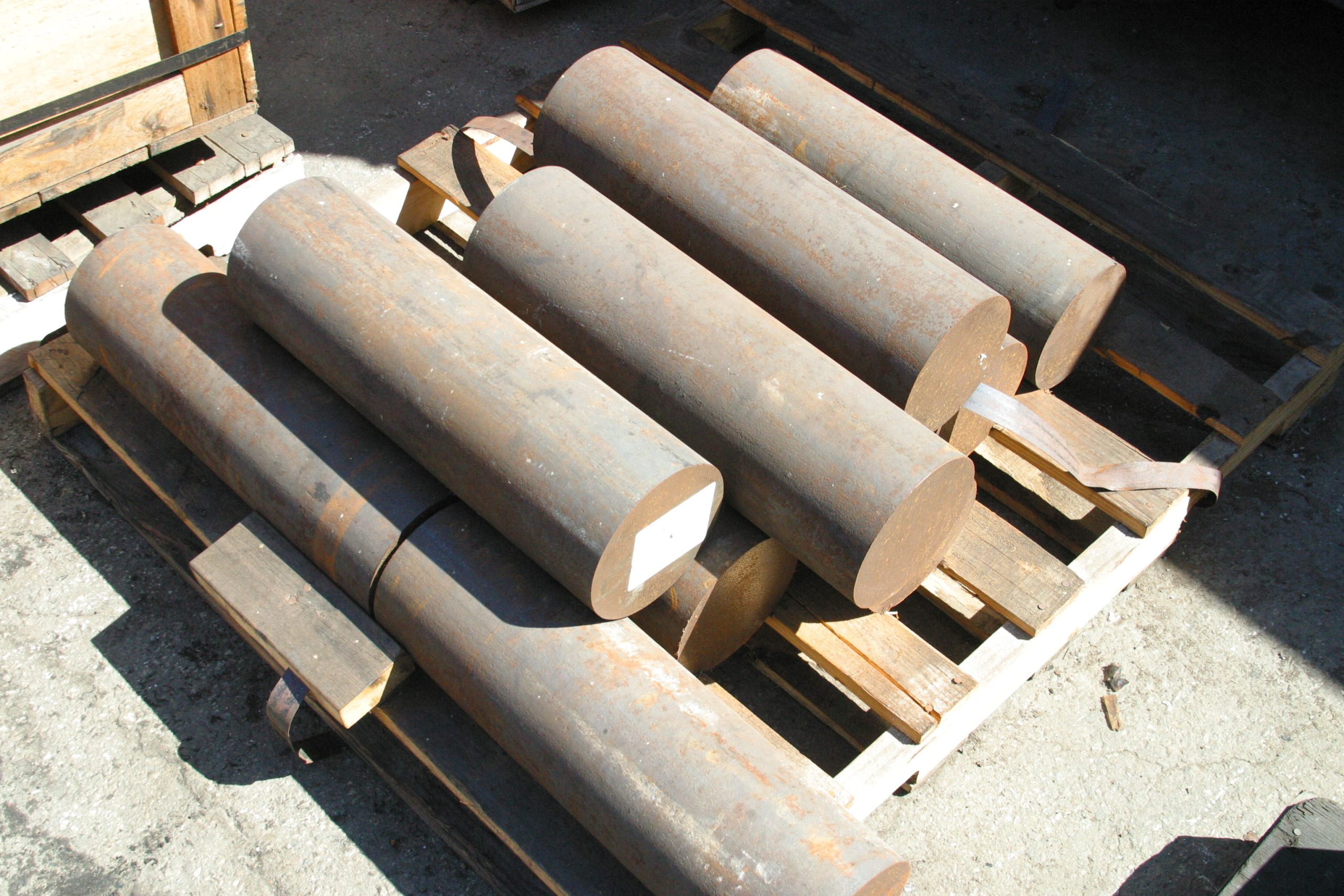
A typical complete stroker kit includes an increased stroke crankshaft, connecting rods, main and rod bearings, pistons, and rings. Crankshafts can be either forged or cast. It is important to understand terminology while you’re shopping for a crank. You will see “cast iron” and “cast steel” mentioned when describing a crankshaft.
Cast Iron typically refers to gray iron, ductile iron and malleable iron which is normally an iron casting with carbon content higher than two percent. Cast Steel normally refers to carbon steel and alloy steel which is a steel casting with carbon content lower than two percent. When you get right down to it, cast steel and cast iron are basically the same thing with a slight difference in alloy content.
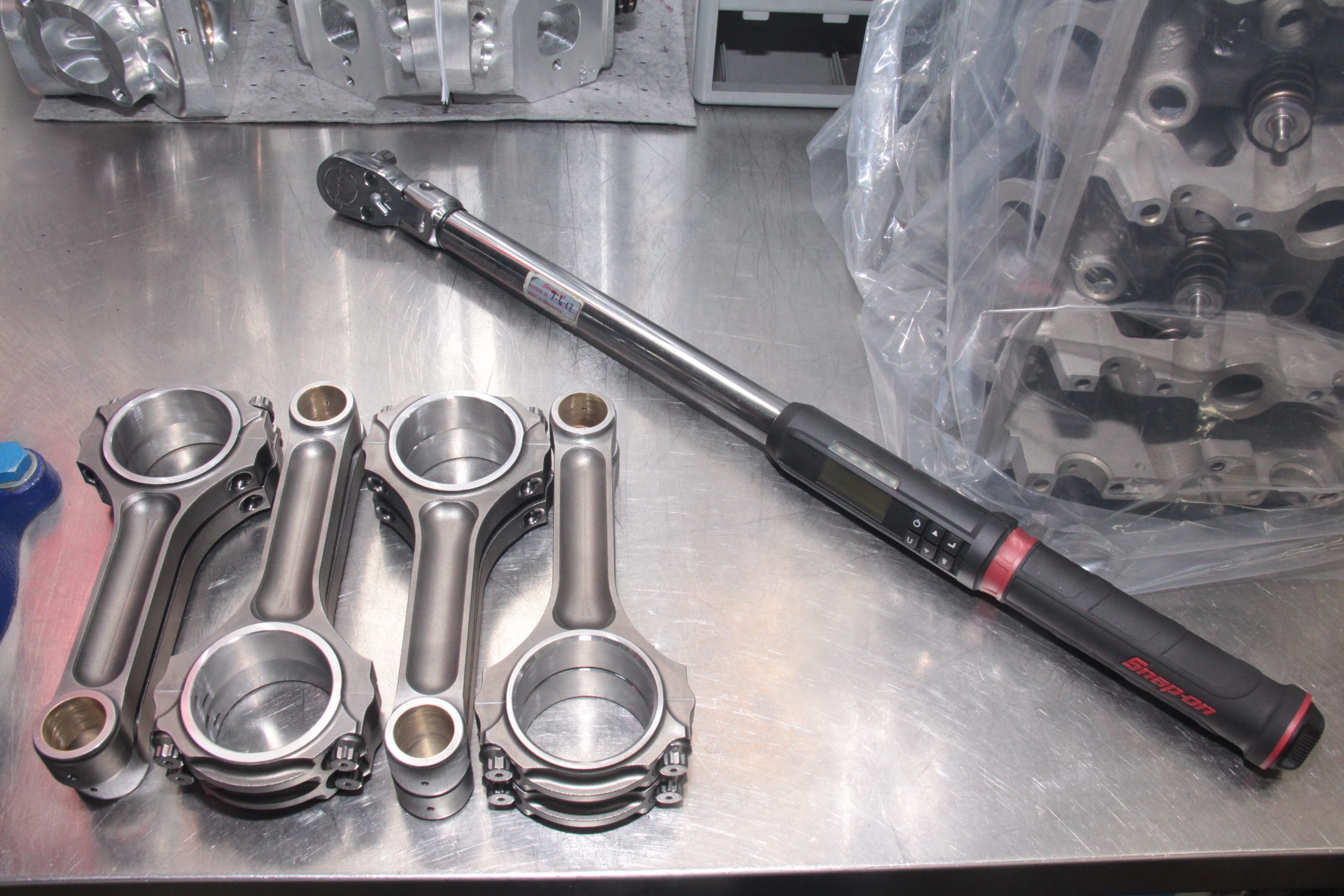
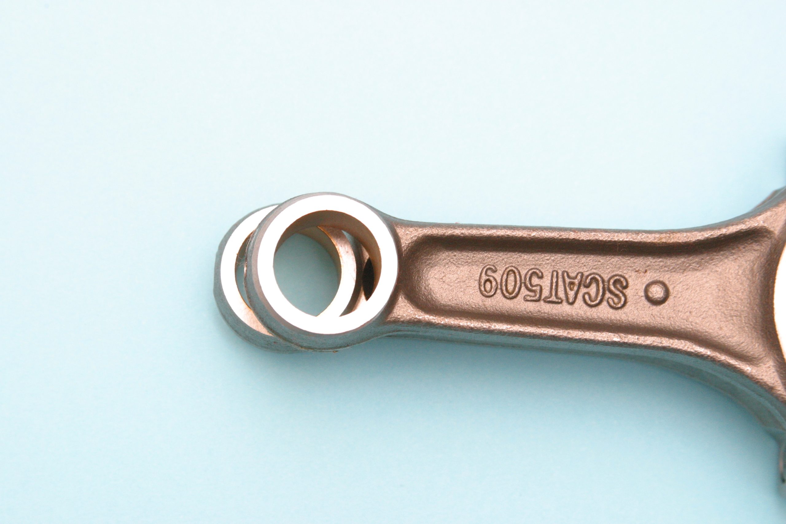
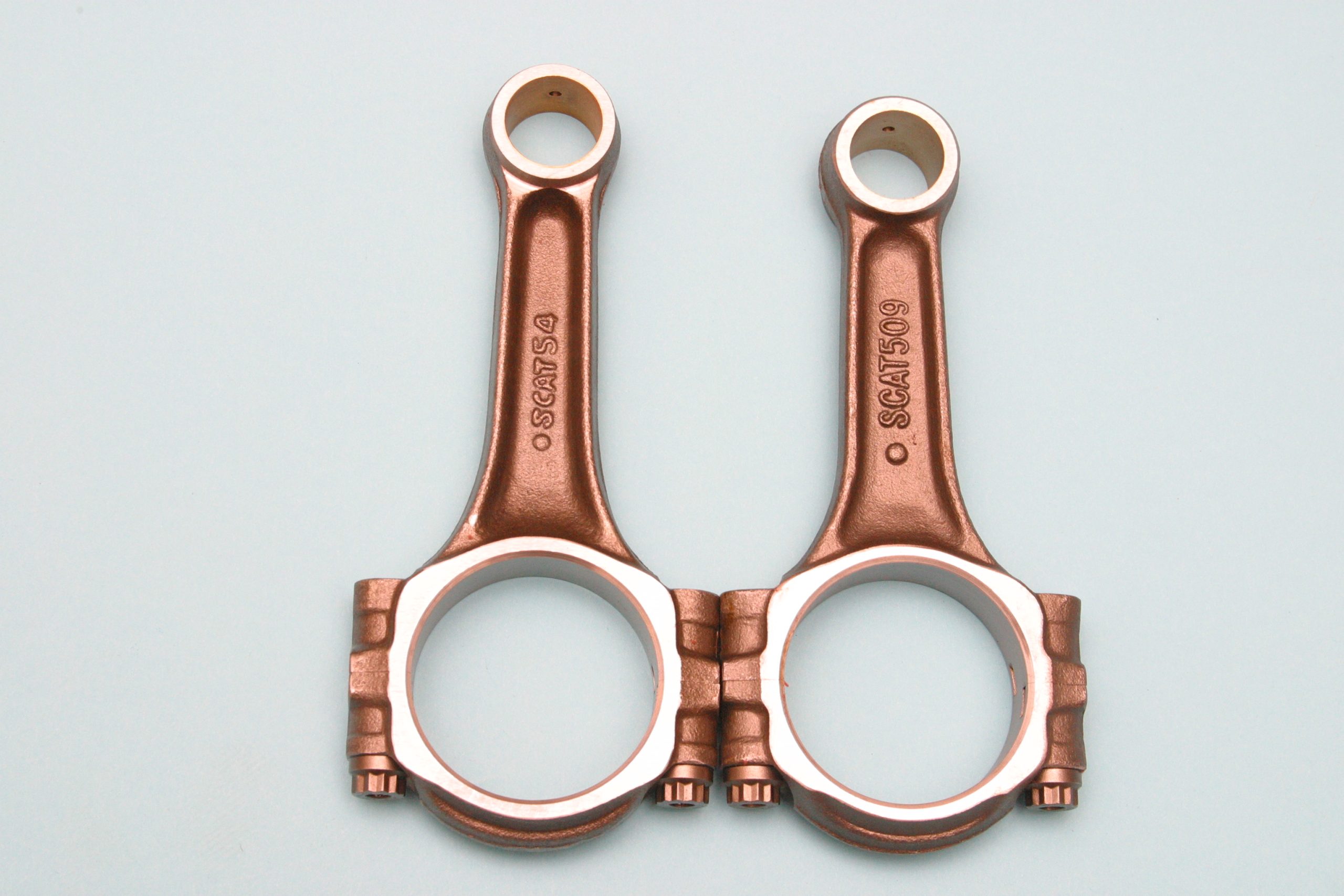
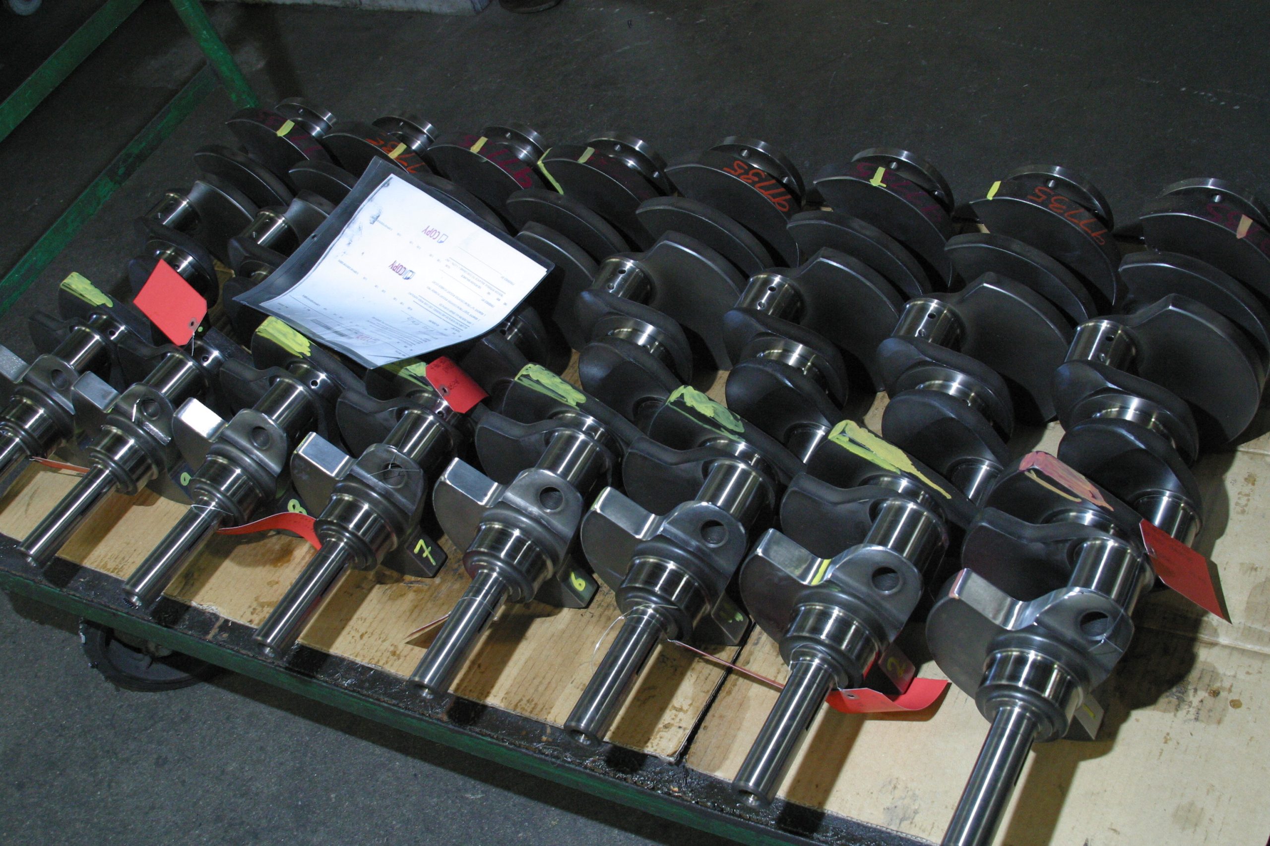
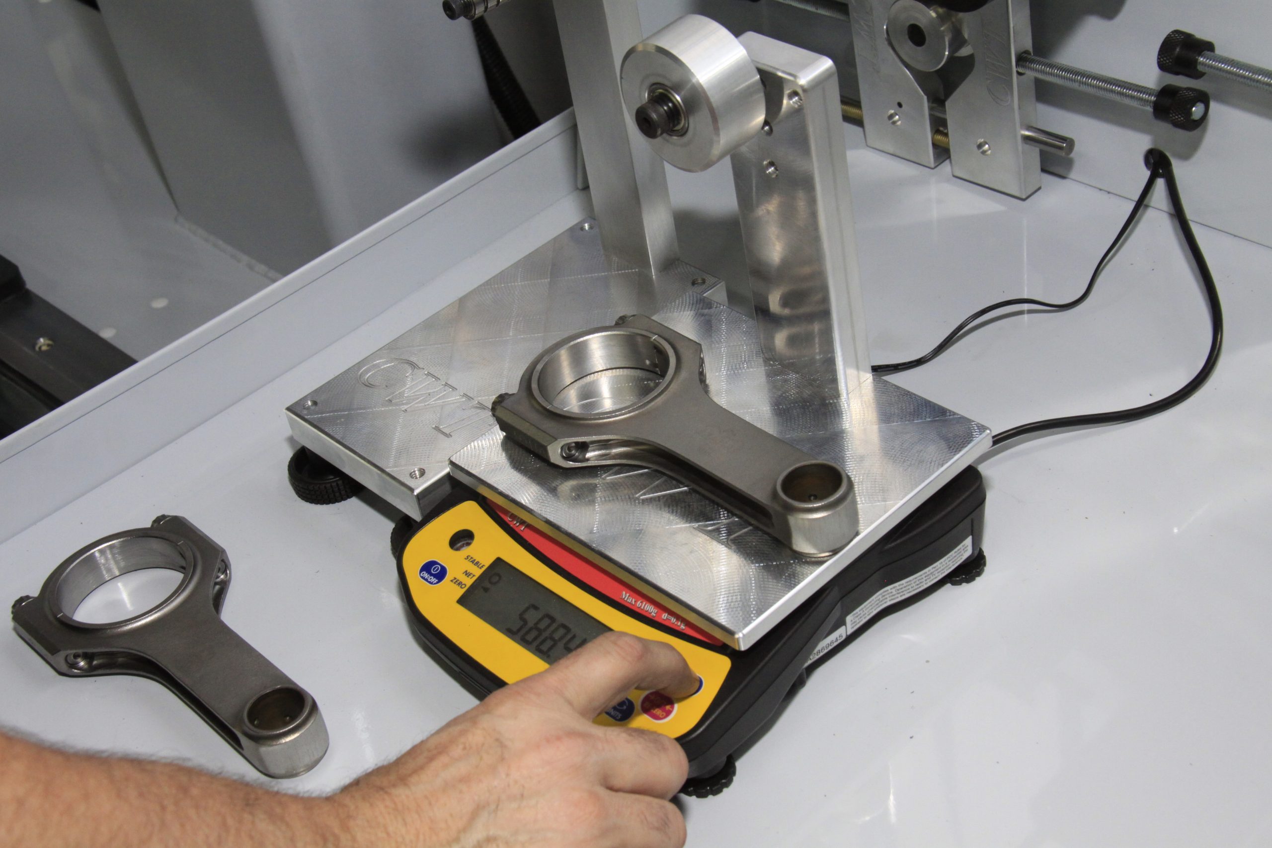
Forged cranks are more expensive and certainly stronger. Connecting rods are either forged I-beam or H-beam. H-beam will be stronger and more expensive. There are also brute strength I-beam rods to choose from. Scat Enterprises offers five different types of connecting rods—Stock Replacement, Pro Stock I-Beams, Pro Series I-Beams, Pro Sport H-Beams, and the Ultra Lite Pro H-Beam. Everything but the Stock Replacement is bushed at the piston. The Stock Replacement is pressed pin or bushed. All rods are fitted with ARP bolts or studs.
SCAT Connecting Rods exhibit the high-end craftsmanship we’ve come to expect from SCAT. SCAT connecting rods are made from a two-piece chromoly steel forging to ensure maximum strength and durability, which is what you want from a connecting rod. They offer a complete line-up for Small and Big Block Chevy; Chevy LS; Small and Big Block Ford; Ford Modular 4.6L and 5.0L; Ford Vintage Model A/B/T; Ford Flathead; Small and Big Block Chrysler; Pontiac; Sport Compacts; and more.
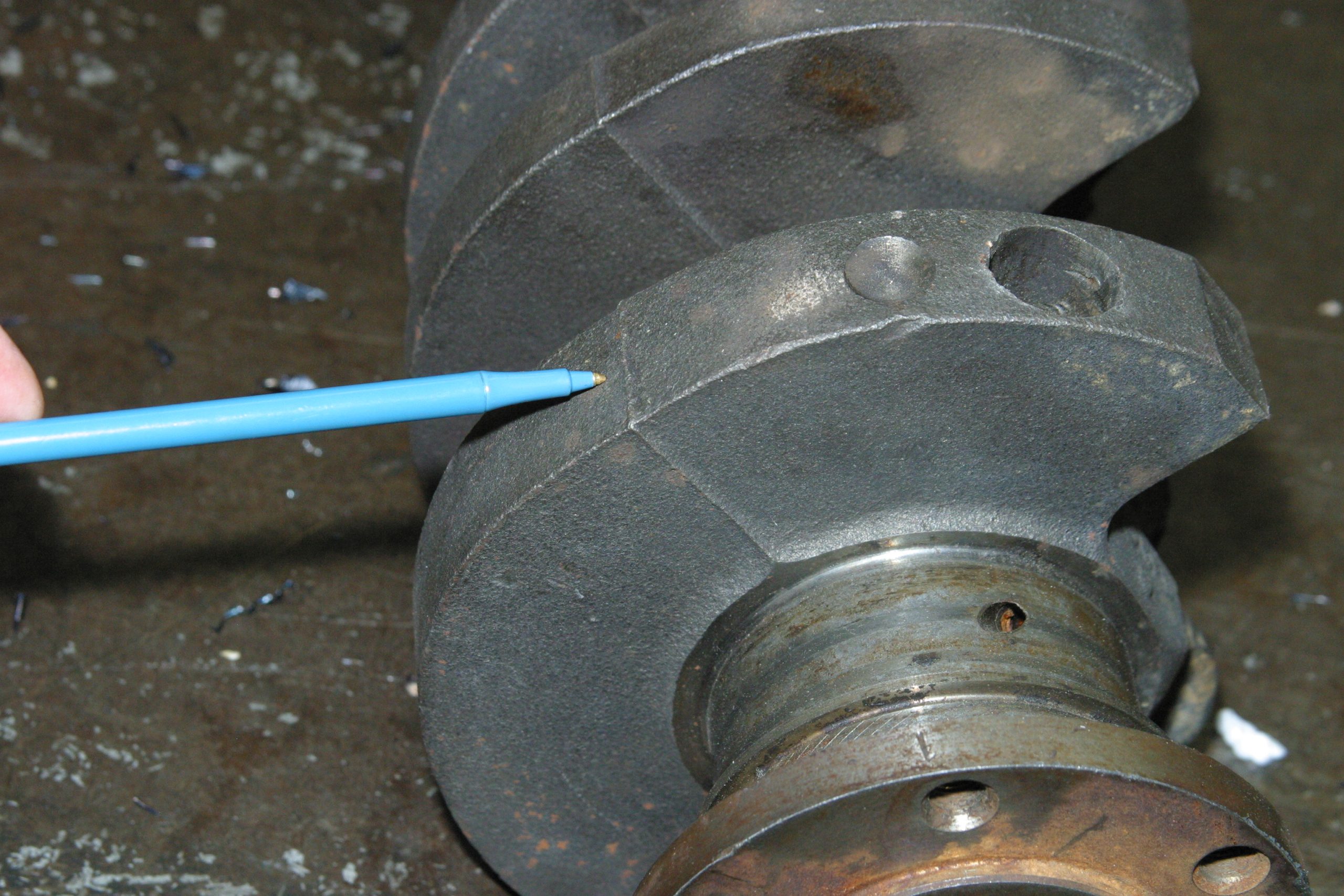
When you consider the crankshaft’s arm, which is the distance from the crankshaft centerline to the center of the rod journal, this is where torque comes from. Torque is an engine’s “grunt!” factor. Grunt is that physical pressure at your backside when the accelerator is pressed. Think of the crankshaft’s arm as a simple lever, like you were taught in high school physics. Torque equals the downward force of the stroke times the length of the lever or arm. If you, for example, take a Ford 5.0L engine’s 240 ft.-lbs. of peak torque, this means each cylinder bore is producing 480 pounds of pressure on each power stroke. Torque is increased when you increase the length of the arm. When you increase the length of the arm, you increase stroke.
A stock 5.0L engine’s arm is 1.5 inches. This means the 5.0L engine has a 3.000 inch stroke. If you add 0.25 inch to the arm, this increases the arm to 1.750 inches. Double the 1.750 inches and you have 3.500 inches to achieve 351ci with the standard 4.00 inch bore. This gives you 40 additional pounds-feet of torque. Overbore the cylinders 0.030 inch and you get 355ci. Push the bore to 4.060 inches and you’re courting 360ci. You are also courting more torque.
Downsides to a Stroker Motor
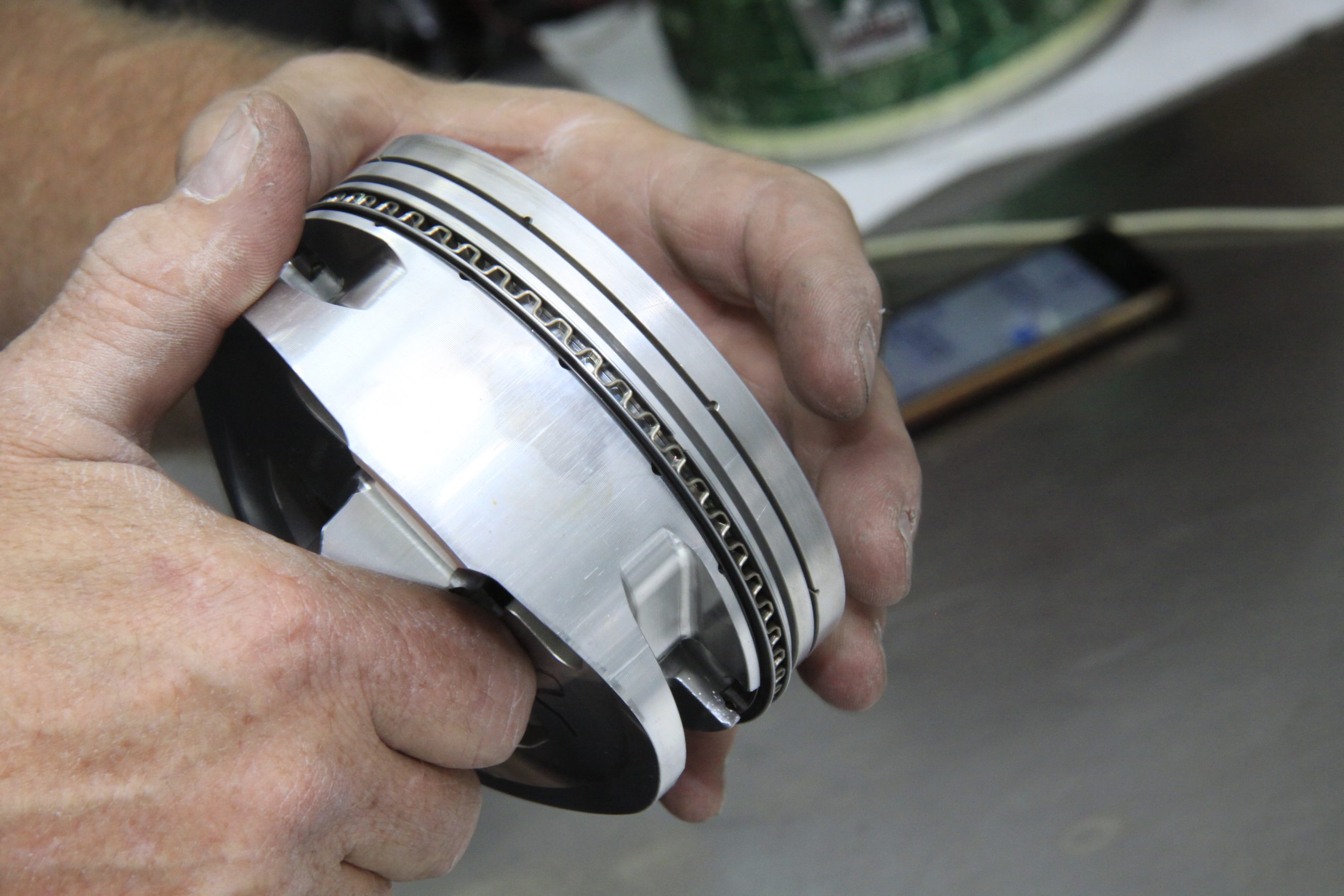
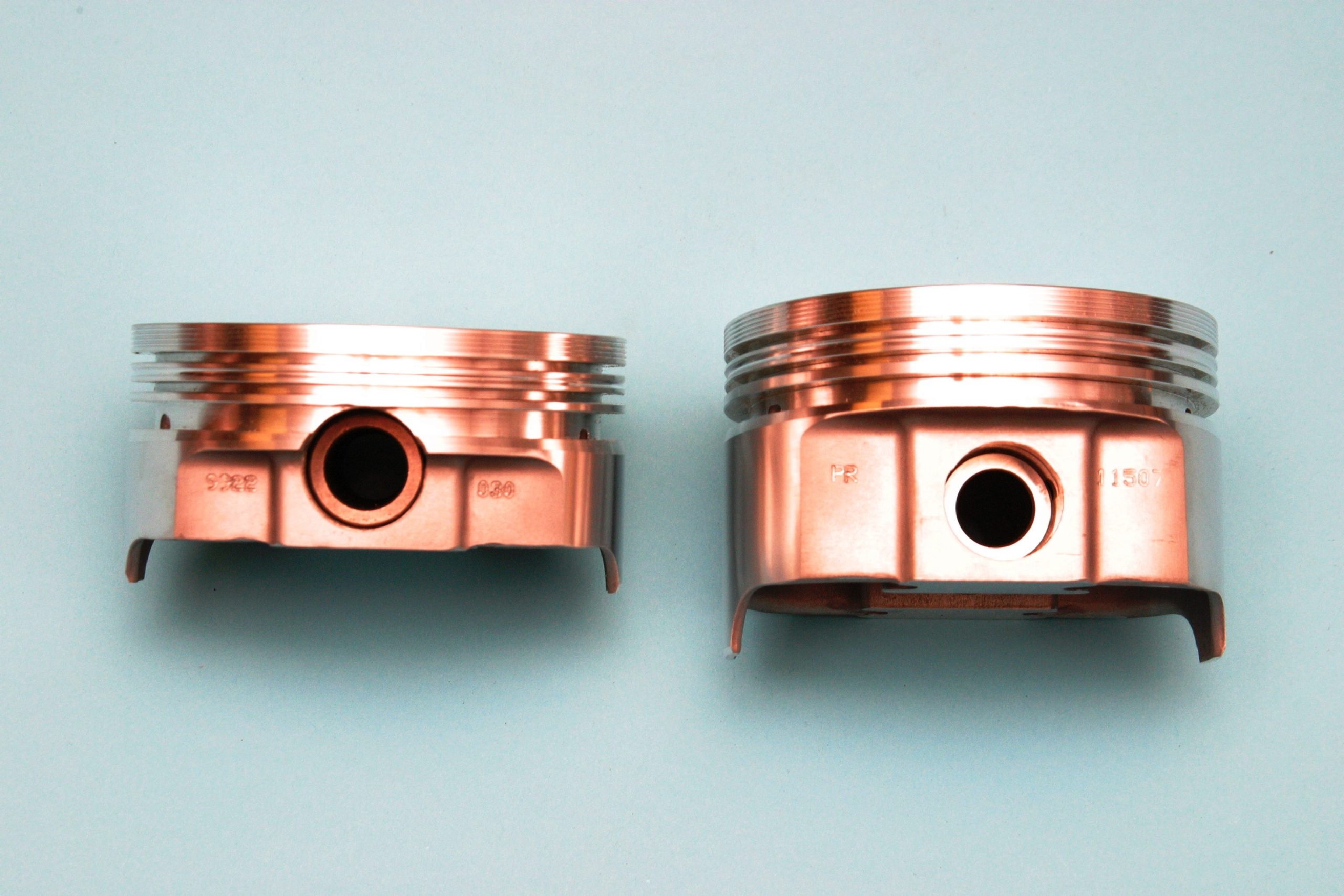
Despite the advantages of a stroker, there are disadvantages as well, especially if you’re bent on pumping the most displacement possible into an engine. When you stroke an engine to its limits, you lose piston skirt, which hurts piston stability. You’re also pushing the piston pin into the piston ring land area, which weakens piston design. It also puts the pin close to the piston dome, which exerts too much heat on the pin and boss causing oil breakdown. This shortens engine life.
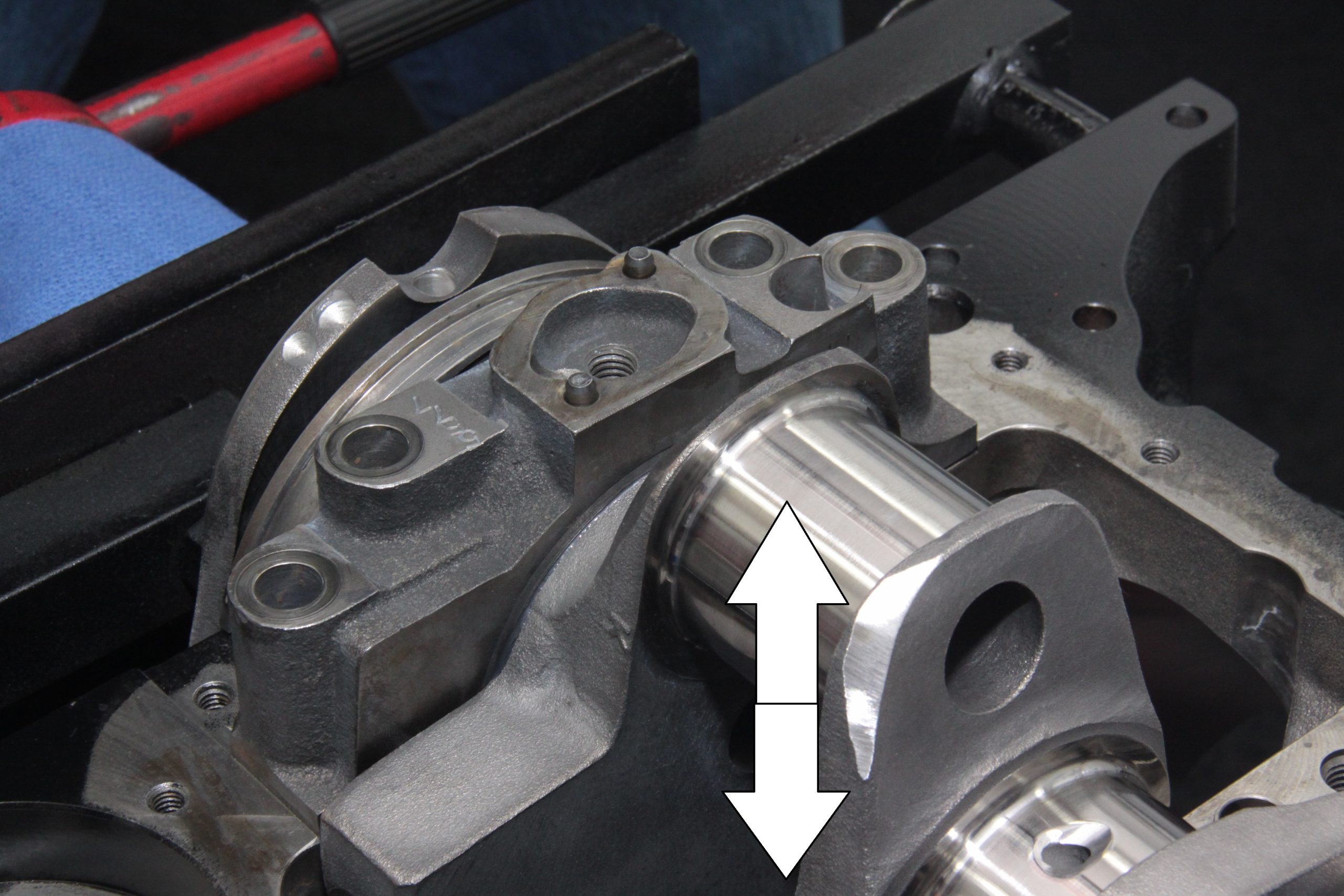
Another issue with stroking is rod length. When you haul the piston deep into the cylinder bore, you’re also bringing it closer to the crankshaft counterweights, which creates potential conflict. This means you need a longer connecting rod to get the piston down there without interference with the counterweights. oftentimes, you can find off-the-shelf connecting rods to complete your stroker. And sometimes, you’re forced to custom make connecting rods that will work. More affordable kits have off-the-shelf parts that have made the kit possible without expensive tooling costs.
An important issue is rod ratio. The longer the rod, the higher the rod ratio. Optimum rod ratio is as close to 2:1 as you can get. This means a rod length as close to twice the stroke as possible. This means the most dwell time possible at each end of the bore for the best cylinder fill and scavenge.
Bore, Stroke & Compression Ratio
Whenever you increase stroke, you are squeezing more volume into the same combustion chamber. This means you must address the increase in compression. With the increase in stroke and compression comes an increase in cylinder volume. In that volume comes an increase in air and fuel, which yields more power.
What is compression ratio all about and how is it best understood? One popular misconception is that pistons, alone, determine compression ratio. But this has never been true. Compression ratio comes from not only piston dome features (such as dome or dish), but stroke, bore, and combustion chamber size.
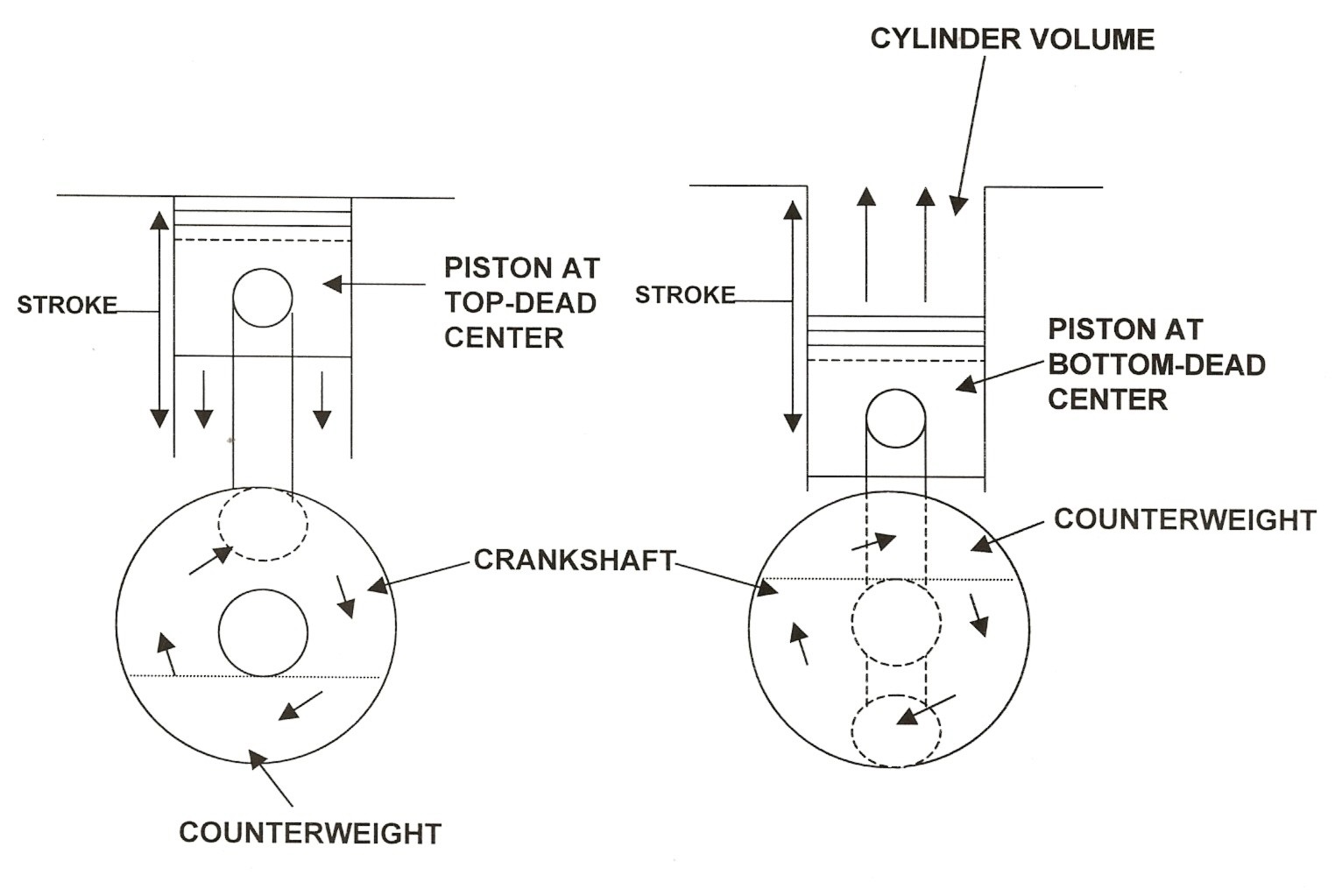
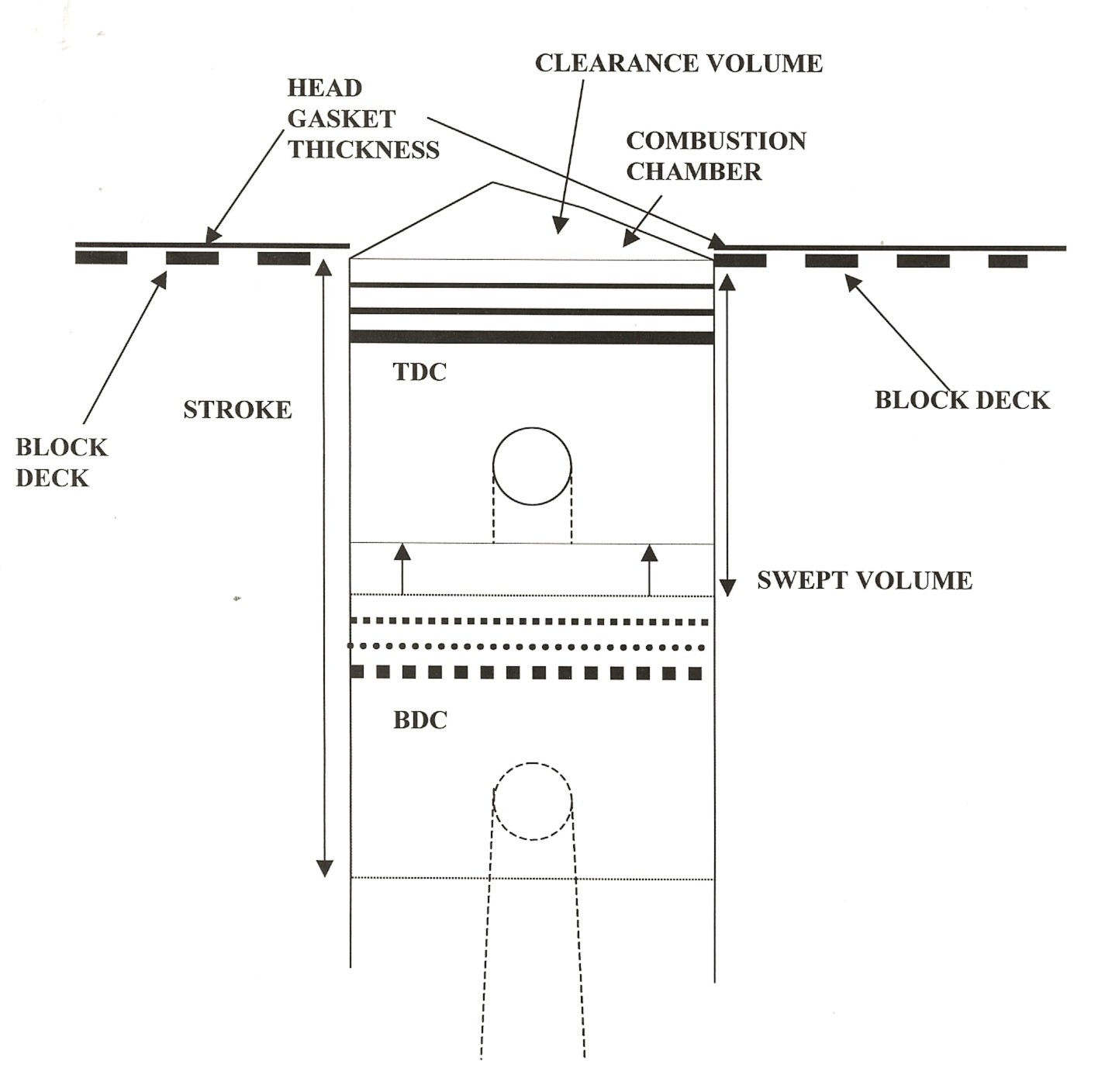
Compression comes from piston travel from bottom-dead-center to top-dead-center with both valves closed. You are simply squeezing the cylinder volume (displacement) into the combustion chamber. This is known as compression ratio. Compression ratio is cylinder volume at bottom-dead-center versus cylinder volume with the piston at top-dead-center. If cylinder volume with the piston at bottom-dead-center is 10 times more than it is with the piston at top-dead-center, then we have a compression ratio of 10.0:1, or simply 10 to 1.
Five basic factors affect compression ratio. Cylinder swept volume, piston dome shape, head gasket thickness, clearance volume, and combustion chamber size. Swept volume is how much air or volume the piston displaces during its journey to the top of the bore. If we enlarge the swept volume by boring the cylinder oversize or increasing stroke, we increase compression ratio.
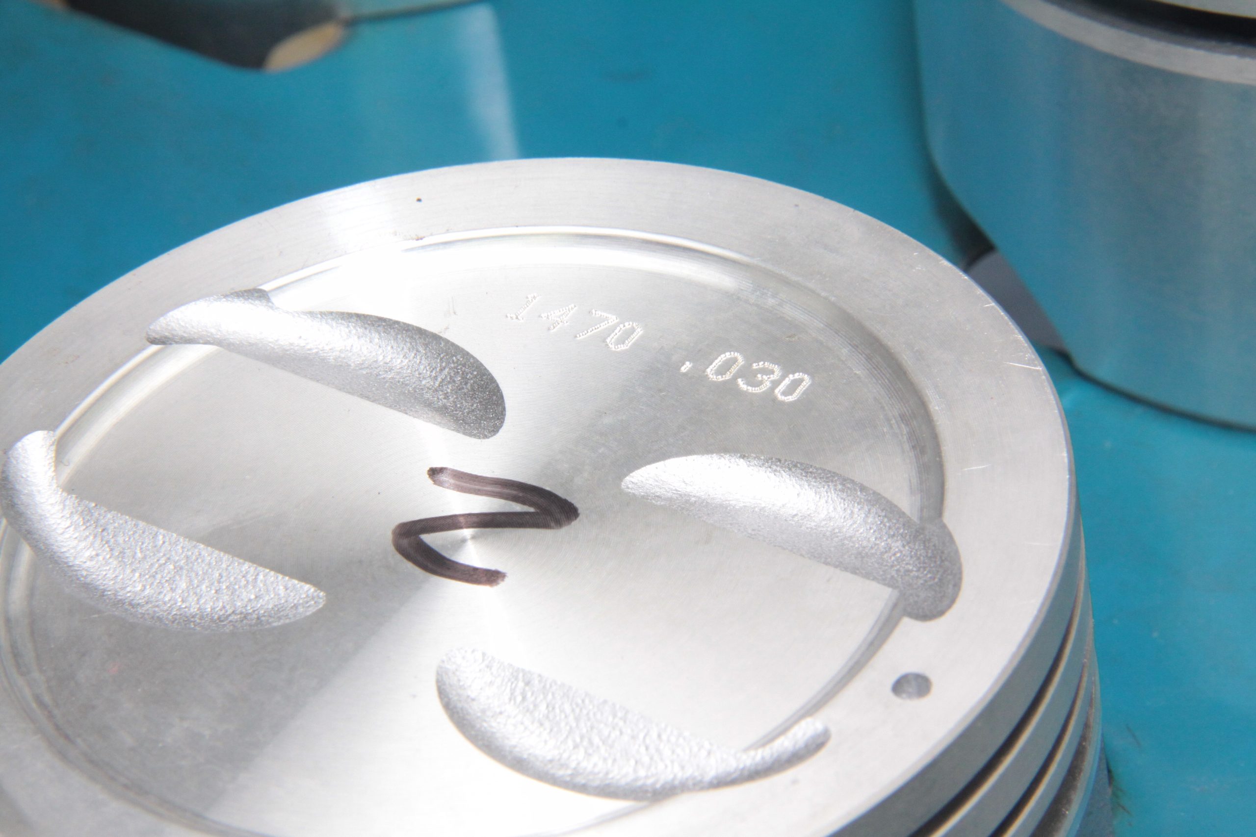
You may also increase or decrease compression ratio by changing the piston dome. If you “dish” the top of the piston, you lose compression. This is common with stock pistons that are often dished to reduce compression. To raise compression ratio, you can “dome” the piston, with a surface shaped like the combustion chamber. This reduces clearance volume at the top of the bore. When you reduce clearance volume, you increase compression ratio. Compression ratio may also be increased by reducing combustion chamber size.
Whenever you step up to an aftermarket head, keep combustion chamber size in mind. Most aftermarket heads for small-blocks, as one example, have chamber sizes around 64cc. If you desire greater compression, you can make adjustments with piston selection. Compression ratio may also be increased or decreased by changing combustion chamber size. Increasing chamber size reduces compression ratio. Decreasing chamber size increases compression ratio.
If you take a standard 4.000 inch bore (small block) and overbore it by 0.030 inch to 4.030 inch, compression will increase by a fraction of a compression ratio point. If you have compression ratio of 10.0:1, compression will increase by less than a point with a 0.030 inch overbore. Compute the compression increase (or decrease) by figuring the clearance volume, which is the area left above the piston when it reaches top-dead-center.
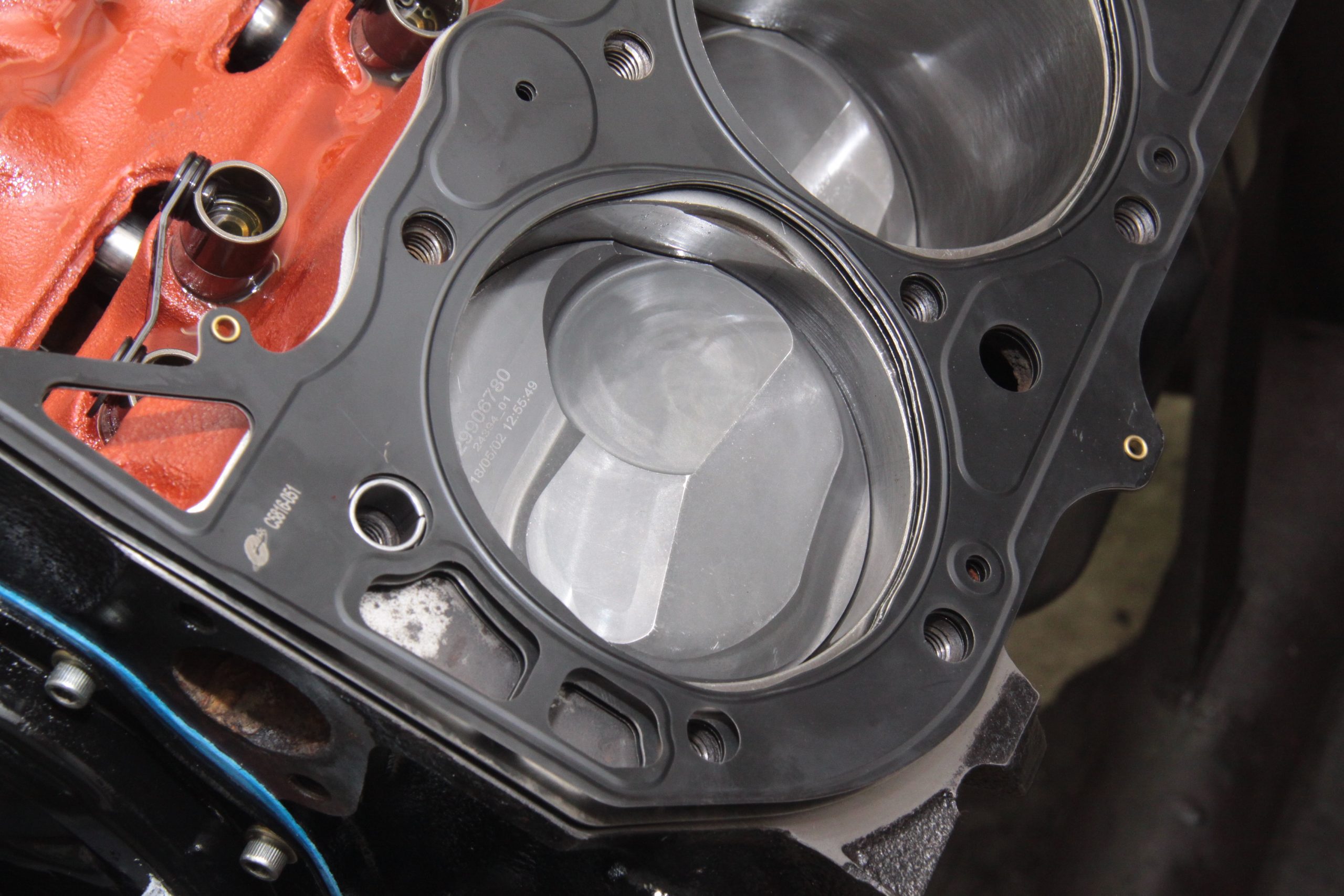
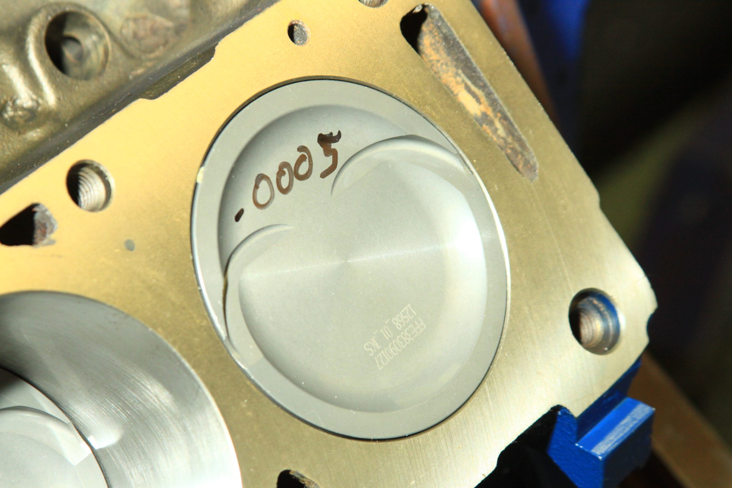
It is important to understand the piston doesn’t always reach top-dead-center flush with the block deck. Sometimes, it can be out of the bore. In most applications, the piston comes within 0.005 to 0.020 inch below the deck surface. It looks more flush with the block deck than it actually is. This is called piston deck height. Piston deck height affects compression because it determines clearance volume at the top. If you have a lot of clearance volume, you have less compression. The greater the piston deck height, the lower the compression ratio.
Let’s look at a Ford 351ci small block V8 with a 4.000 inch bore and 3.50 inch stroke. The sample 351 has a piston deck height of 0.015 inch below the block deck. When you use the formula of 0.7853982 x 4.000 inch to the second power x 0.015 inch, you get 0.188ci, or just a fraction of the cylinder’s 43.98ci. If piston deck height increases any amount, compression will drop. If piston deck height is decreased any amount, compression will increase.
After figuring how to compute displacement in each cylinder and how to figure in piston deck height effect on compression, it is time to figure in the piston’s role in all of this. Remember, if you dish the piston, you lose compression. If you dome the piston, you increase compression. Most piston manufacturers will give you the specifications on a piston. If it is dished, the manufacturer will tell you how much in cubic centimeters or CCs. The same can be said for a domed piston.
The next issue in compression ratio is cylinder head gasket volume (thickness), which contributes to the clearance volume above the piston. The thickness of the head gasket (volume) affects compression ratio. The thicker the head gasket, the greater the clearance volume. This lowers compression. The thinner the head gasket, the lower the clearance volume, which increases compression.
Combustion chamber volume is the actual size of the chamber in cubic centimeters. Think of the combustion chamber as the ultimate clearance volume. Chamber sizes for most small block V8 engines range from 53cc to 64cc.
Getting Real World Power
We’ve long been led to believe horsepower is the dominate power number. However, “horsepower” is rooted more in Madison Avenue advertising rhetoric than fact. When it comes to power, horsepower counts at high rpm, but not necessarily where we use the engine most of the time. What really counts is torque and when we have the most of it. Engines make torque (twist) when we feed fuel and air into combustion chambers and squeeze the mix. Steve Brule of Westech Performance in Ontario, California has often said, “Torque is the grunt that gets us going, and horsepower is the force that keeps us moving…”
This has always been true.
Engines do their best work when they reach peak torque when they’re making the most grunt. Steve adds that when an engine is below the torque peak, it has more than enough time to completely fill the cylinder with air and fuel. He adds that when engine rpm rises above the torque peak, there isn’t enough time to completely fill the cylinders with air and fuel.
The power we feel from an engine’s spinning crankshaft is torque multiplied by engine speed (rpm) to produce a number that tells us something about the engine’s output. This theory dates back to old steam engines and an inventor named James Watt. Watt invented the steam engine long ago in the 1800s. Watt’s theory was a simple one. It compared the work his steam engine could do with the same work an equal number of horses could do. Watt determined a single horse could pull a 180 pound load 181 feet in one minute’s time. This formula figured out to 32,580 lbs.-ft. per minute. Watt rounded it off to 33,000 lbs.-ft. per minute. He divided this figure by 60 seconds, which worked out to 550 lbs.-ft. per second.
And this became the standard for one horsepower.
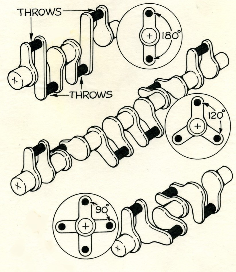
As a result of Watt’s theories and calculations long ago, horsepower has become a measure of force in pounds against a distance in feet for the brief period of one minute. Then, we take this formula and apply it to an engine’s crankshaft at each journal throw to arrive at horsepower. This is based on the number 5,252. Torque and rpm are divided by 5,252. And torque and horsepower always pass each other at 5,252. If you are able to solve this equation at 5,252 rpm, rpm cancels out, ultimately leaving horsepower equal to torque. In fact, if you work this out on a graph, the torque, horsepower, and rpm lines should always intersect.
When we observe torque alone, it is the measure of an engine’s work. Horsepower is a measure of how quickly the engine does the work. Torque comes from displacement and stroke mostly. This means the real power we derive from an engine comes in the torque curve. The broader the torque curve, the better our power package. A broader torque curve comes from making the most of the fuel/air mixture across a broader rpm range. This is best accomplished with a longer stroke and a larger bore. And this is what strokers are all about. Strokers are about making the most torque across the broadest range. Truth is, we’re never going to get the best of everything, even with fuel-injected engines. Our engines need to be planned and built based on the way we’re going to use them. What we choose in terms of a camshaft, cylinder heads, and induction system determine how our engine will perform.
There are plenty of myths about making power. To learn how to make power, we have to understand how power is made to begin with. How much power an engine makes depends on how much air and fuel we can pump through the engine, plus what we do with that fuel and air mixture during that split-second it lives and dies in the combustion chamber.
Think of an internal combustion engine as an air pump. The more air and fuel we can “pump” through the cylinders, the more power we’re going to make. This is why racers use big carburetors, manifolds, heads, superchargers, turbochargers, and nitrous oxide. Racers understand this air pump theory and practice it sometimes with reckless abandon (and sometimes with catastrophic results). But good racers also understand the too much of a good thing theory. Sometimes it can cost you a race. It can also cost you an engine.
Getting power from the “air pump” takes getting liberal amounts of air and fuel into the chambers, then squeezing the mixture as hard as we can without damaging the engine. When you raise compression, you increase the power the mixture yields. It is the intense heat of compression coupled with the ignition system spark that launch the yield of energy from the mixture. The more compression there is, the greater the heat energy we have to ignite the mixture.
Downside is, when there’s too much compression, and the resulting heat, the air/fuel mixture can ignite prematurely resulting in preignition and detonation. This means you have to achieve the right compression ratio to get the most from the fuel we have. Today’s street fuels won’t tolerate much over 10.5:1 compression. This means having to look elsewhere for answers in the power equation, like more aggressive camshaft profiles, better heads, port work, hotter ignition systems, exhaust headers that breathe better, state-of-the-art intake manifolds and carburetors, even electronic fuel injection where we never thought of using it before.
The important thing to remember about gasoline engines is this. The fuel/air mixture does not explode in the combustion chambers, it “lights off” just like your gas furnace or water heater in something of a quick fire. Because the mixture is compressed and ignited, it lights off more rapidly. Combustion in a piston engine is just that, a “quick fire” that sends a flame front across the top of the piston. Under ideal circumstances, the flame front will travel smoothly across the piston dome, yielding heat and pressure that act on the piston and rod uniformly to create rotary motion at the crankshaft.
A bad “light off” that originates at two opposing points in the chamber is the pre-ignition or detonation factor we were talking about earlier. The opposing light offs collide creating a shock that hammers the piston dome, which is the pinging or spark knock we hear under acceleration. The objective is to get a smooth quick fire, with the flame front traveling in one, smooth direction for maximum power.
Power management is having the right balance of ignition timing, fuel mixture, compression ratio, valve timing events, and even external forces like blower boost or nitrous input. All these elements have to work together if we’re to make productive power. Let’s talk about some of the elements we need to make power.
For one thing, the science of making power must tie in with your intended vehicle usage. And that’s where most of us get it wrong all too often. In our quest for stroker torque, we sometimes forget how the vehicle is going to be driven and used on a daily basis. If you are building a stroker to go drag racing, the way you build your engine is going to be different than the guy who builds one for trailer towing. By the same token, road racing engines should be executed differently than drag racing powerplants.
Street engines for the daily commute need to be approached for good low and mid-range torque. Drag racing engines need to make power at mid- to high-rpm ranges. Road racing engines need to be able to do it all—down low, in the middle, and at high rpm because they’re going to live in all of these ranges while racing. Engines scheduled for trailer towing need plenty of low-end torque. They also need to be able to live comfortably at mid-range when we’re going to be pulling a grade.
Building a successful stroker boils down to making the right decisions during the planning and execution of your engine build. Always question each decision, and never be afraid to ask questions along the way. Knowledge is your best friend when it’s time to lay down the cash necessary to build an engine.


Very helpful overview of the science of strokers. Thanks for this article!
You talked about the block which is great info. I have a question about the heads which is better for a 454 bored to a 496 stroker it will be used a towing and daily driver. Would it be better to use oval port with 2.06 intake and 1.72 exh or 1.88 intake and 2.50 exh?