The 351 Cleveland story is one of the most befuddling in Ford history. In North America, it was only in production for four years (1970-74), yet it became the hotrodder’s mainstay in Australia well into the 1980s. In fact, the 351C has been as popular in Australia as the small block Chevy, which has significant meaning when you consider the legendary Chevy’s great success for approaching 70 years.
Ford’s 335 Series “Cleveland” existed in two forms in North America—the low deck 351C and the raised deck 400 and 351M. When you look at the two types side by side, the difference in size is quite clear. Enthusiasts get this mixed up all the time, but there is but one truth. The 351C and both the 351M and 400 are not the same engines. They are different beginning with the block and its internals.
The 351C arrived in 1970. The 400 showed up the following year in 1971 to replace the FE Series 390 and 428ci big-blocks in full sized Fords and Mercs. The 400 was a “square” engine meaning it had the exact same bore and stroke—4.000 inches by 4.000 inches.
It was an engine long on growth potential, but never grew any larger. Ford could have grown the 400 to 435 to 450 cubic inches with less weight than a big block. However, there was also the new 429 and 460 cubic inch Ford 385 Series big blocks, which didn’t weigh much more that had this displacement range covered.
In fact, Ford planned 500+ cubic-inches for the big block, which never materialized amid environmental concerns and the Arab Oil Embargo.
The 400 saw steady use in passenger cars through the late 1970s. In 1975, Ford dropped the low deck 351C in North America, instead de-stroking the 400 to 351 cubic inches and calling it the 351M.
By the way, the 400 was never called the “400M” by Ford. It was just the 400. The “351M” designation differentiated the 351C from the raised deck 351M. The 351C and 351M are not the same engine, by the way. In fact, if you have a 351M, you might as well stroke it to 400 cubic inches because both the 351M and 400 employ the same block and roughly the same weight. The 351M was used extensively in Ford and Mercury passenger cars. It also found use in Ford F-Series trucks in 1977-82.
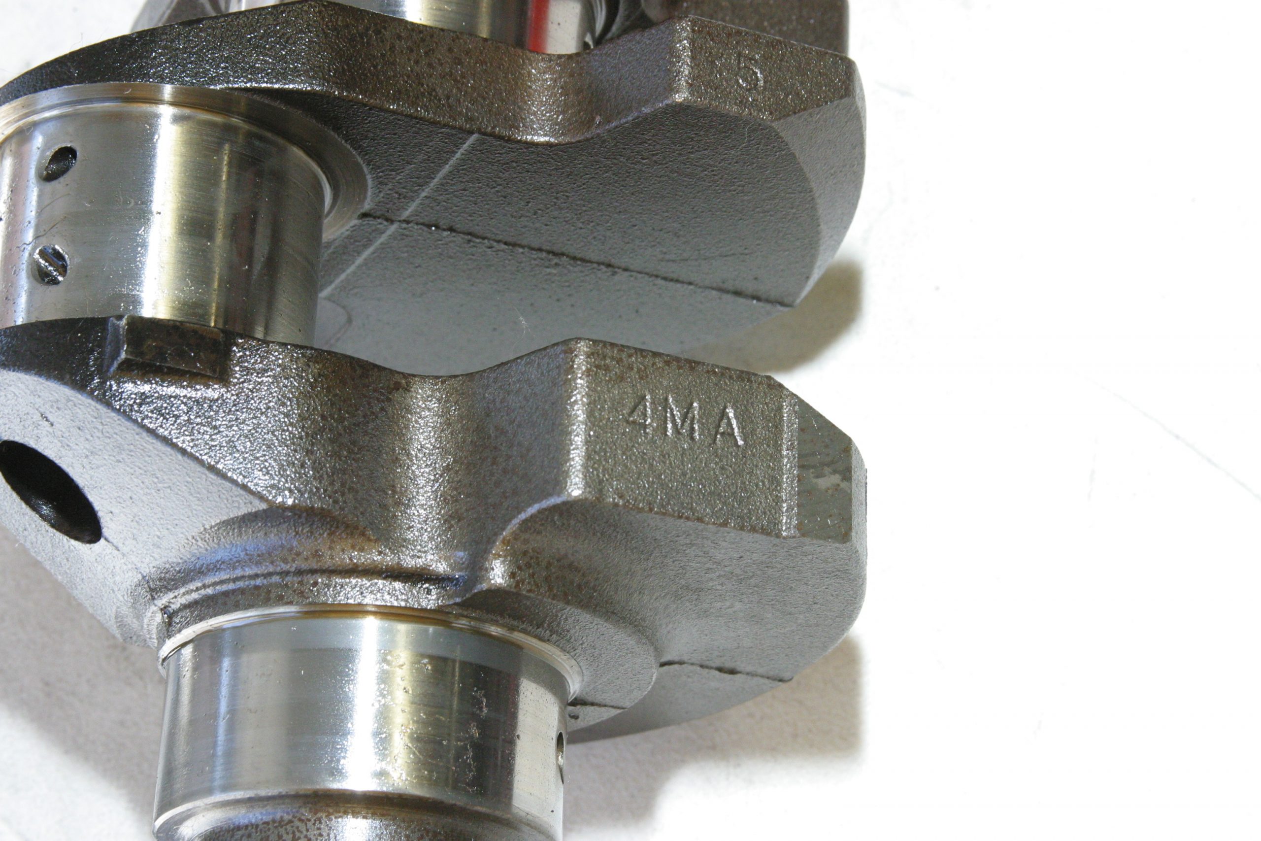
What makes the 351M and 400 different than the 351C is larger main and rod journal sizing along with the raised deck block. The 351C has a 9.206-inch deck height. The 351M and 400 have a taller deck at 10.297 inches. Cleveland crankshafts all look the same, however, they are different. The 4M crank has a 3.500-inch stroke and a 2.750-inch main journal. The 400 crank has a larger 3.000-inch main journal and a 5M stamp. The 351C, 400, and 351M crankshaft identification is “4M” for the 351C and “5M” for the 400. Expect to see “1K” for 351M. Though you see 4MA, 4MAB, 5MA, 5MAB, the additional “A” or “B” is nothing more than an engineering revision to the casting. The Cleveland engines were never factory equipped with a steel crank.
Heads Up…
Understanding how to build power into a Cleveland boils down to knowing how to choose the right cylinder head for these engines. Ford North America never got its act together on 351C cylinder heads. The 351C-4V head had terrific wedge chambers with good quench, yet with ports too large for street use. The 2V head had right sized ports, yet big open chambers with poor quench prone to detonation and hard starting. Some stubbornly stand by these open-chamber heads, however, they’re a poor choice. Ford added insult to injury with the 1973-74 4V head with huge ports and the 2V’s open chambers to get compression down. Instead of controlling compression with a dished piston, Ford made the chambers large like an indoor football domed stadium.
The 400 used the same cylinder heads as the 351C-2V with the same open chambers and smaller “torque friendly” port sizing. Detonation issues drove car owners crazy with these heads. It was the 400’s stroke that yielded the torque.
I’ve been Ford loyalist for decades. I love Ford for its history as a company along with its products. However, I will never understand Ford for its port sizing. Ports were either too small or outrageously large. The 351C is one of the best examples we can think of. The 351C-4V cylinder heads were great high rpm heads with their drive-through ports, which are happiest at 7,000 rpm, but frustrating on the street because they deliver poor low-to-mid-range torque for the street.
Meanwhile, in Australia, Ford continued with great improvements in the 302 and 351C engines. Yes, Ford did a 302 cubic inch Cleveland with even smaller 54-57cc 4V wedge chambers with good quench. The Aussie Cleveland head employed all of the great benefits of a well thought out head—wedge chambers and the smaller 2V ports for a perfect combination of flow and quench.
If you’re building a stock-appearing 351C, but want better performance, this is the head you want (though they’re becoming more scarce all the time).
Summit Racing Performance Heads
Summit Racing offers you an abundance of great aftermarket 351C heads that are also available for the 400. Trick Flow Specialties, as one example, offers several different 351C/351M/400 cylinder head part numbers, which enables you to fine tune your cylinder head selection. You just have to decide which cylinder head is right for your application. Summit Racing can help. Trick Flow has the broadest selection of heads in the marketplace engineered specifically for the 335 Series Ford middle-blocks. The Edelbrock line offers a number of terrific cylinder heads for the Cleveland engine family.
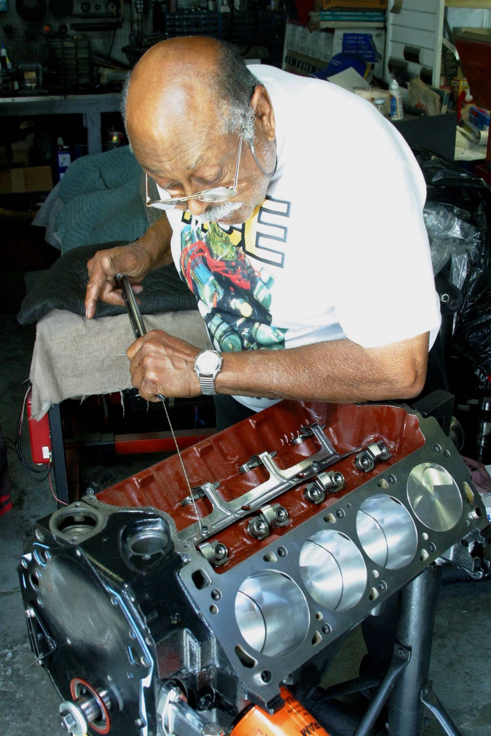
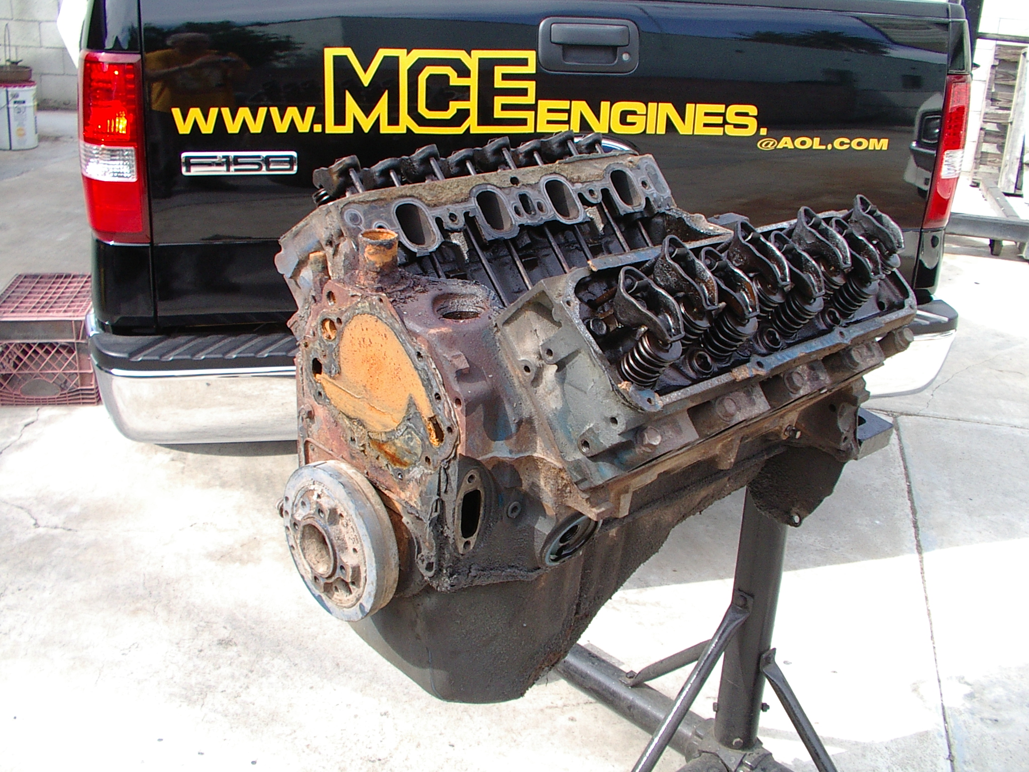
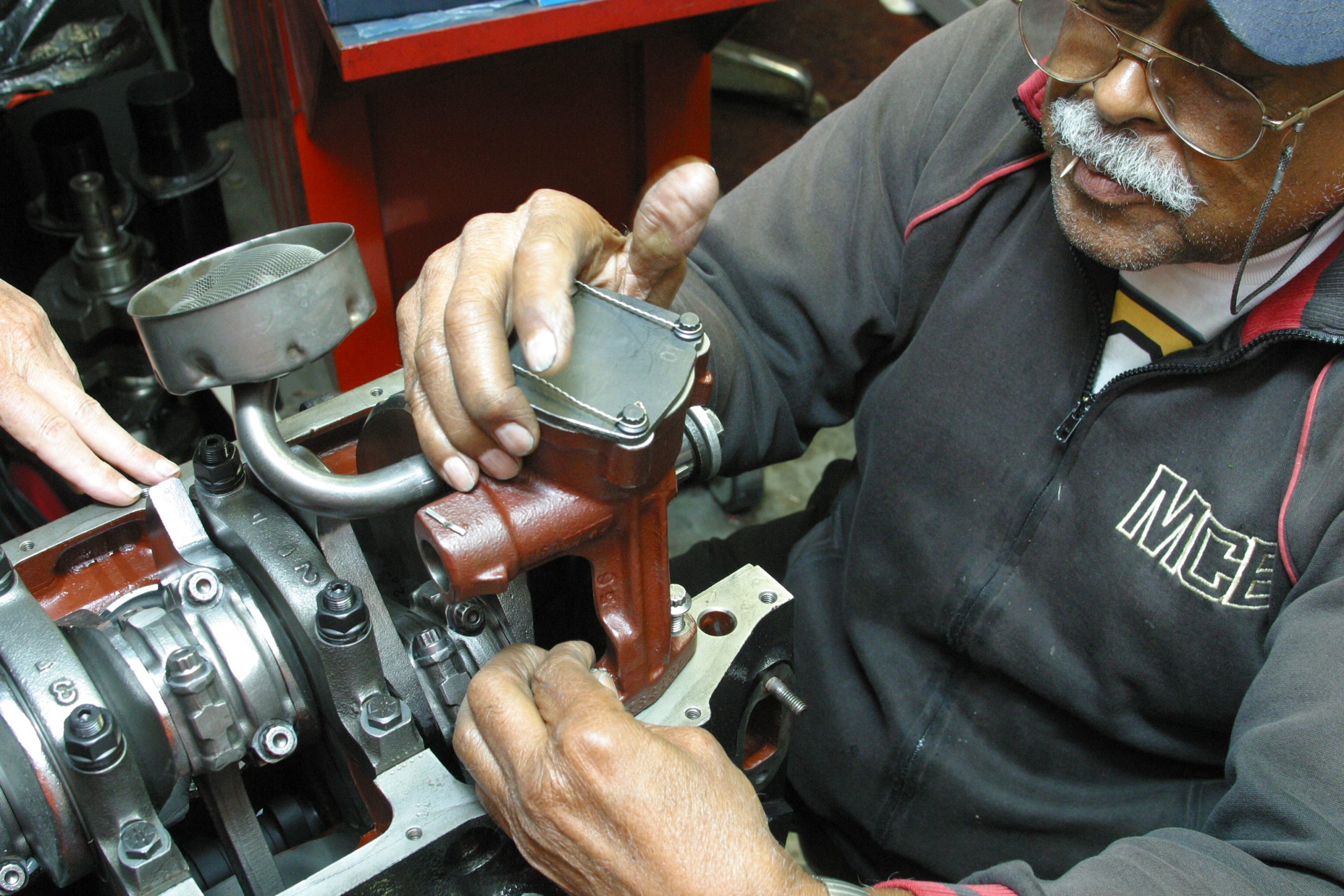
We’re working with the late Marvin McAfee of MCE Engines in Los Angeles on a 351C he was building back in 2008. Marvin lost his battle with old age at 87 last year, but his legacy of great engines remains. This 351C was shipped to Marvin from the Midwest with its share of issues.
Marvin was out to get it right and safely returned.
Let’s Start Our 351C Engine Build
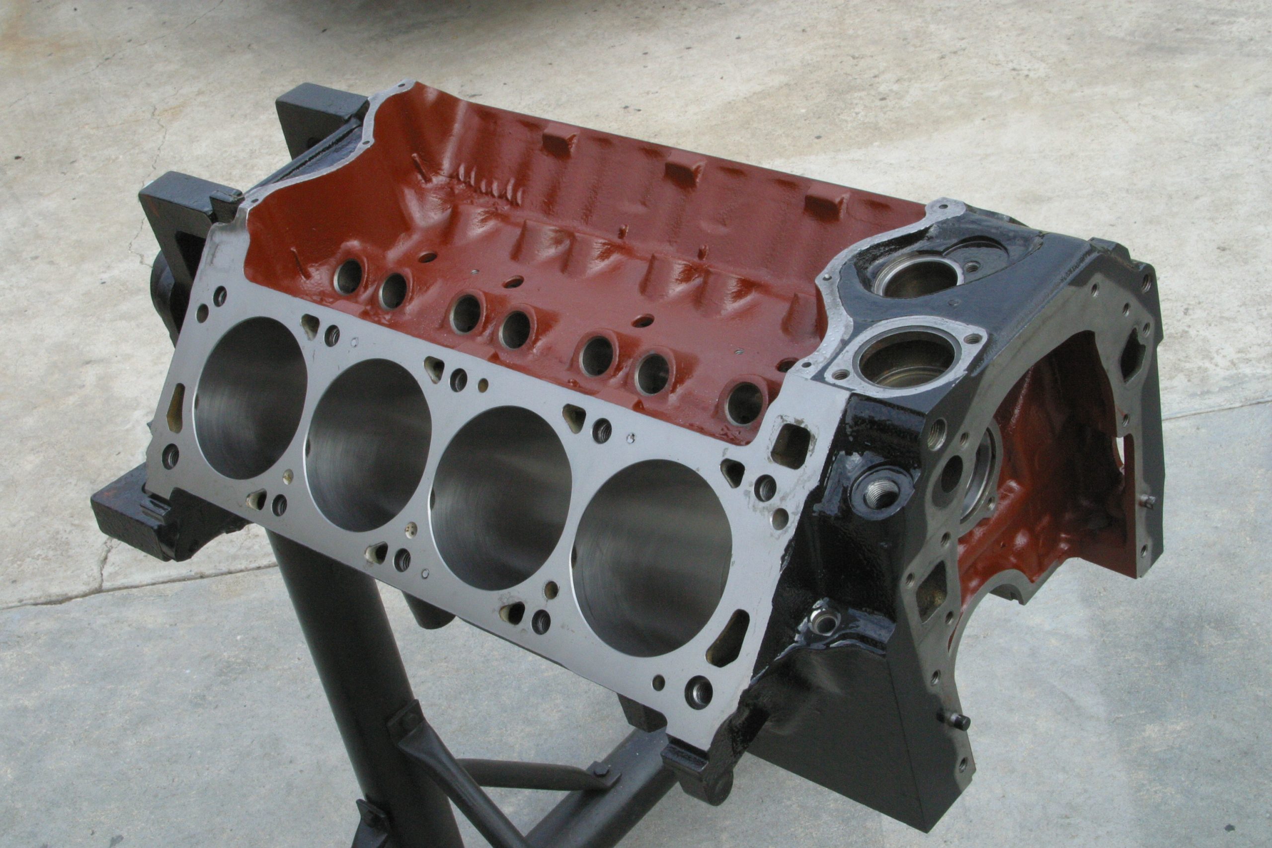
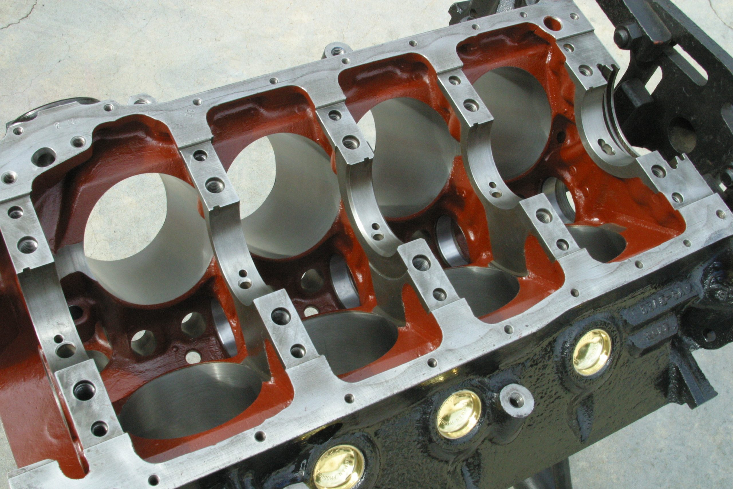
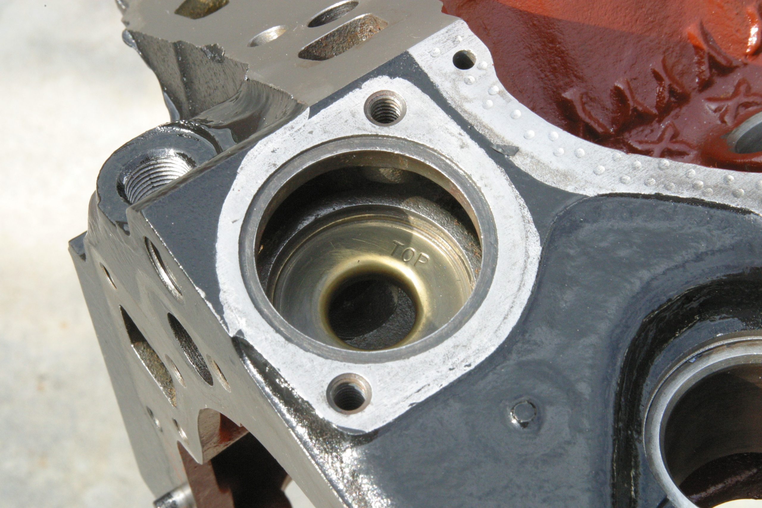
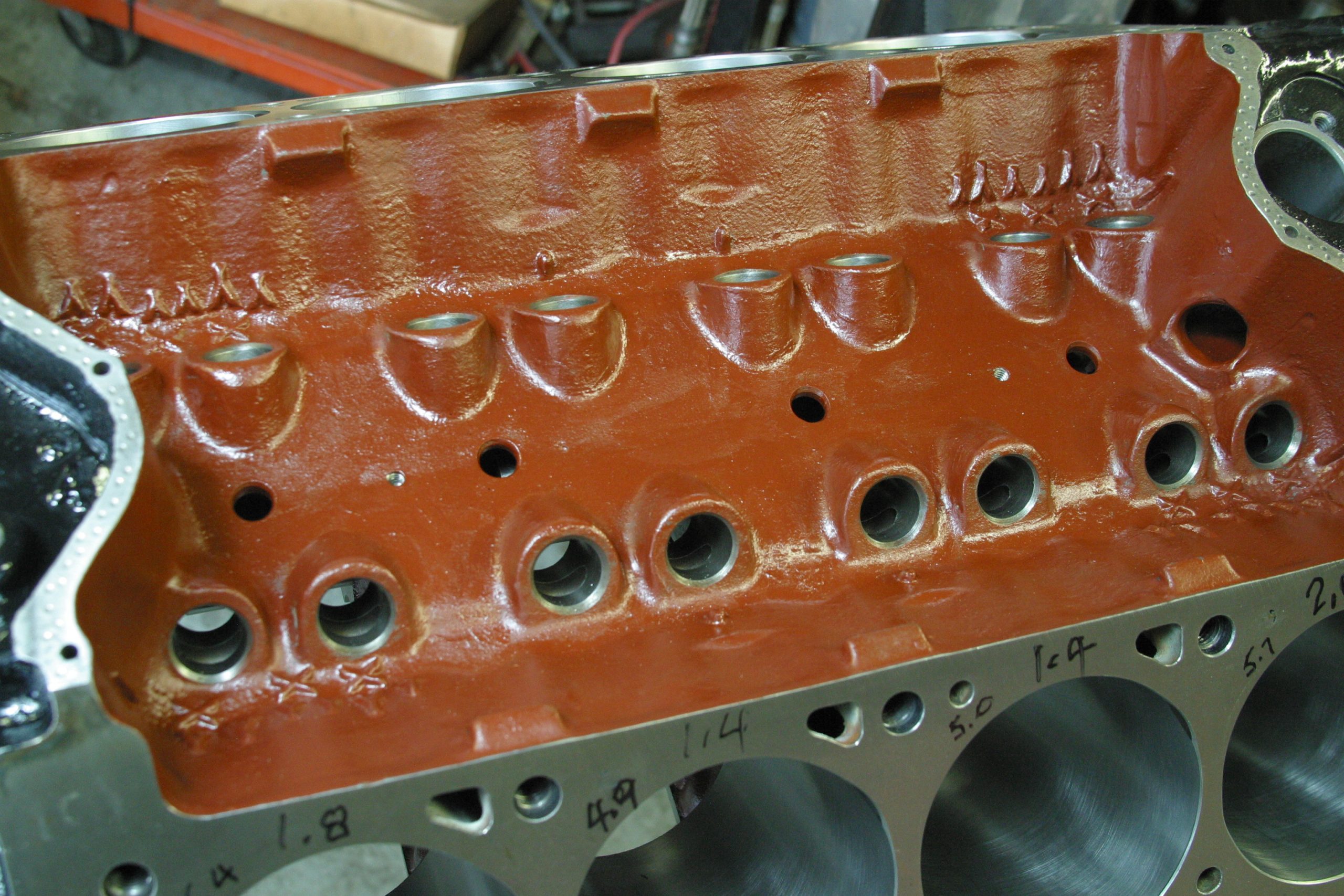
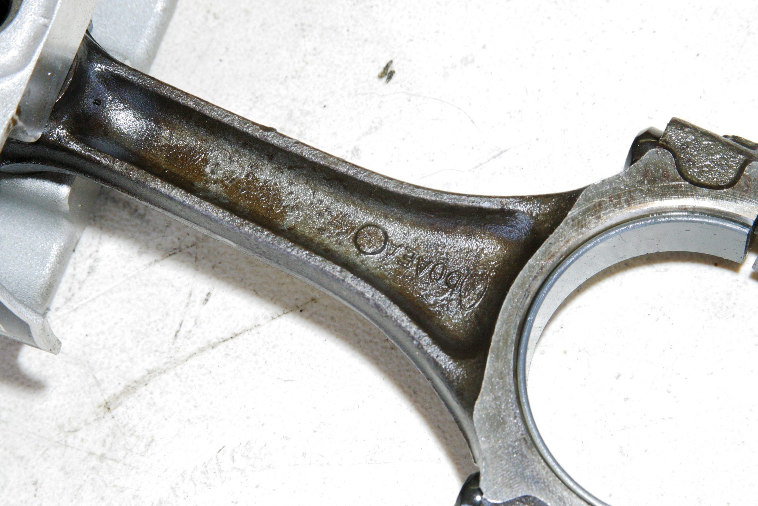
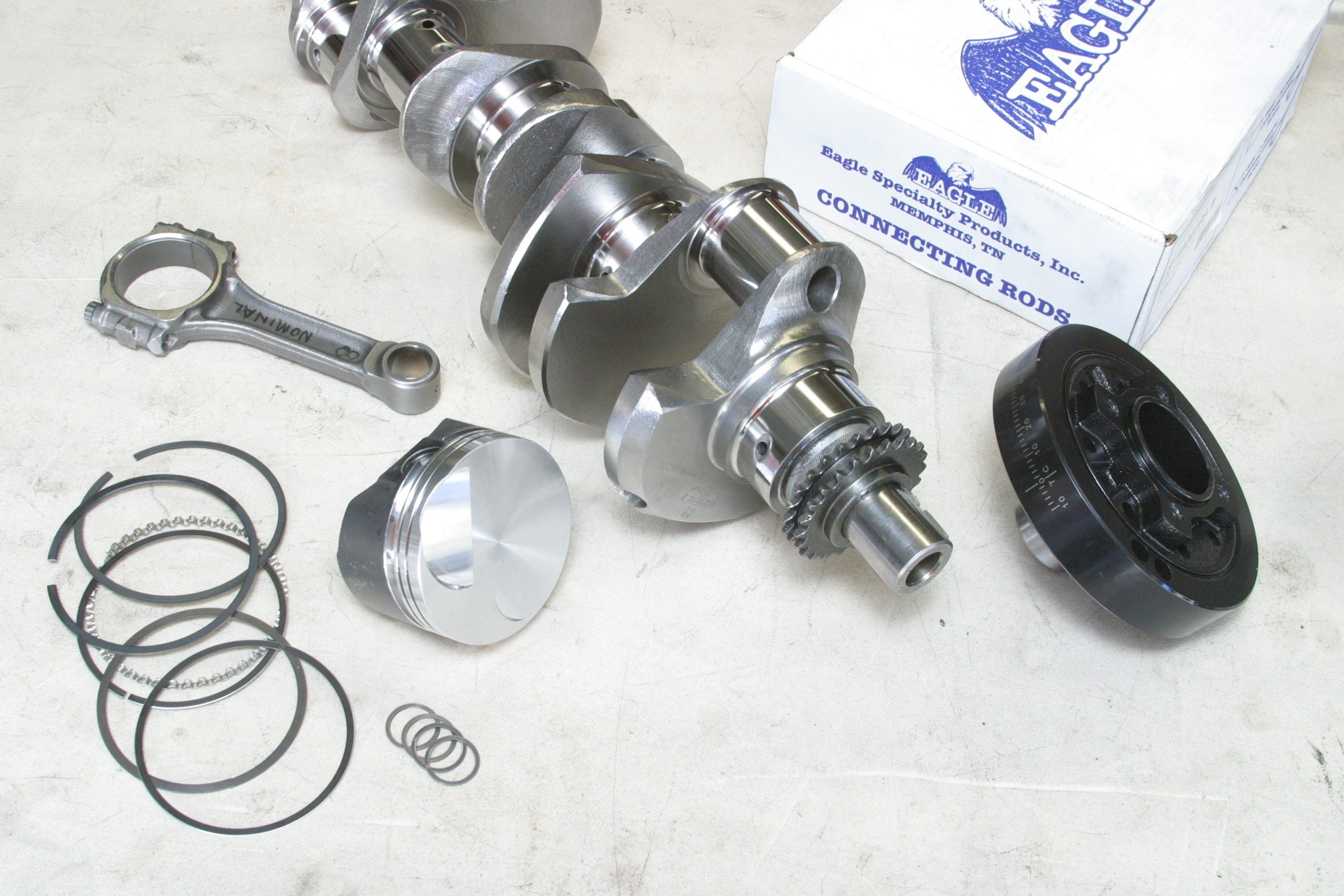
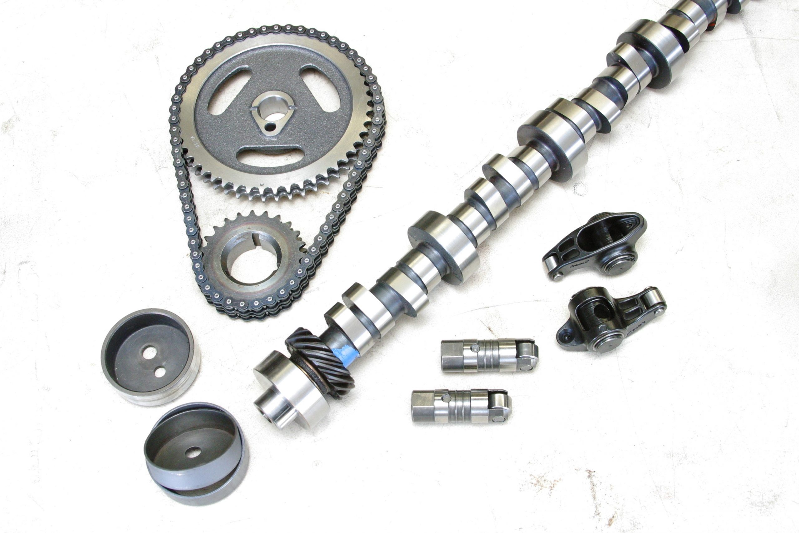
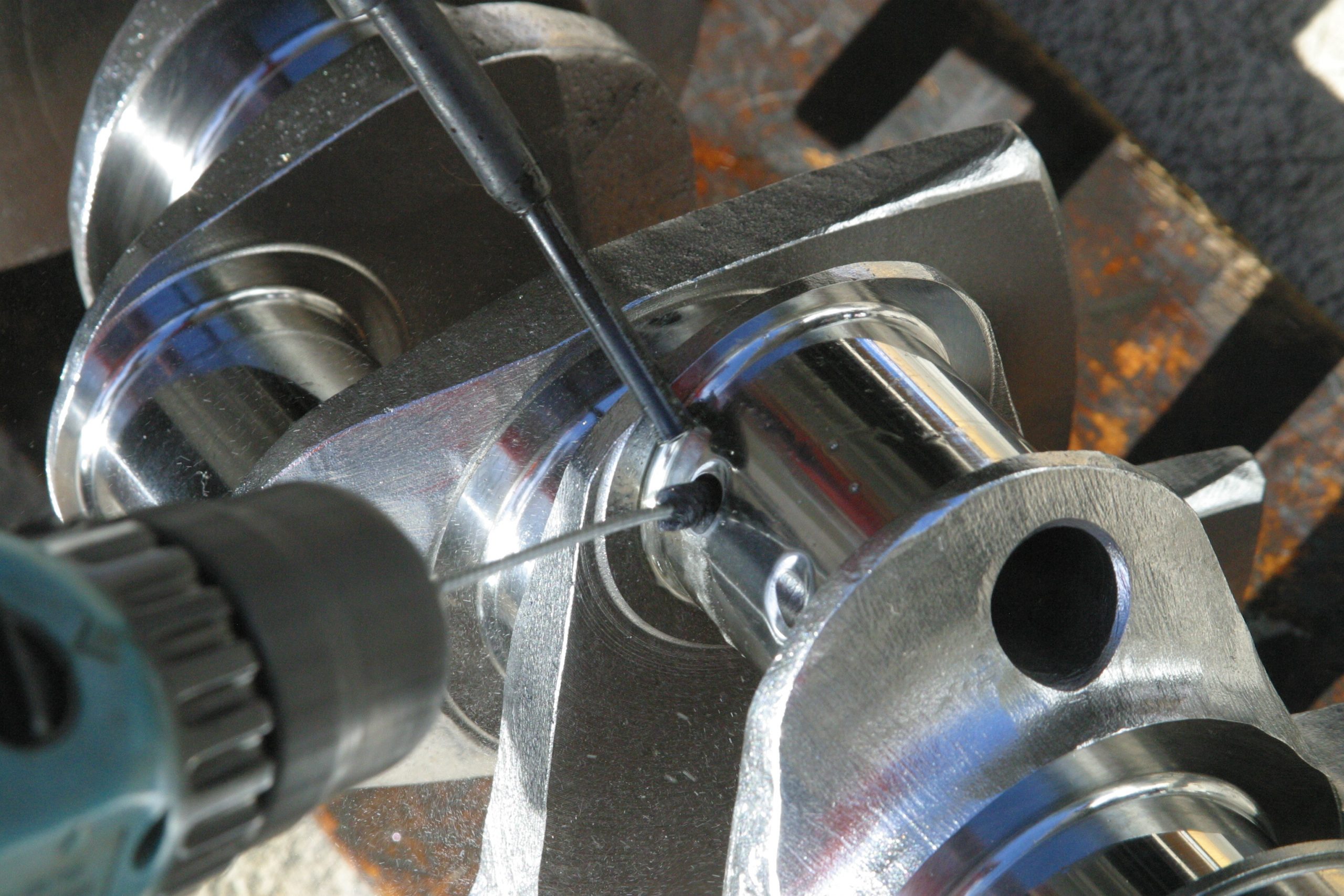
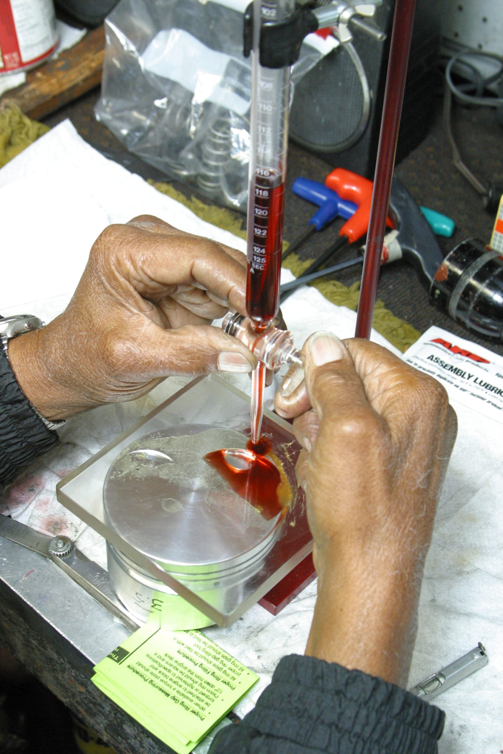
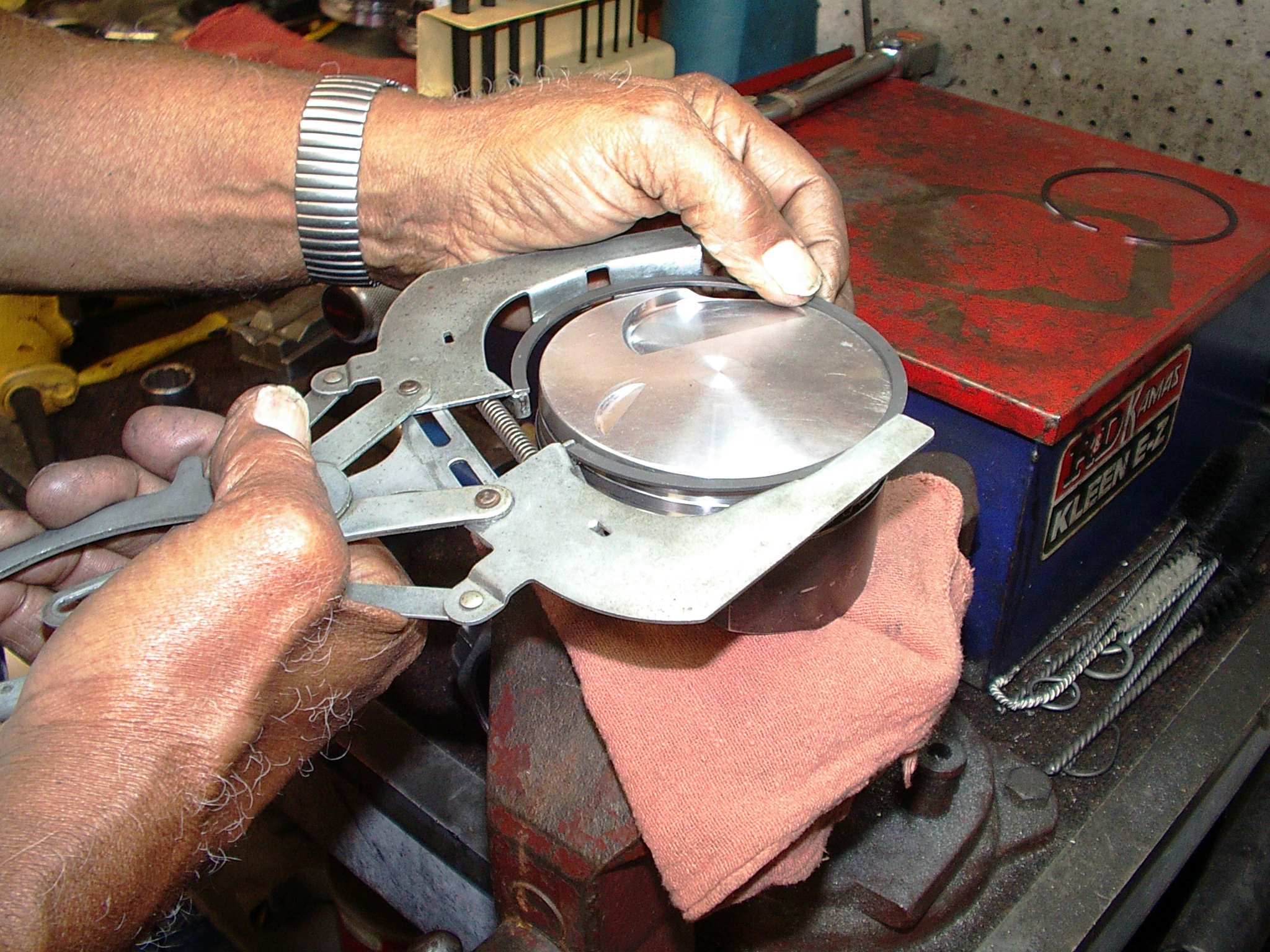
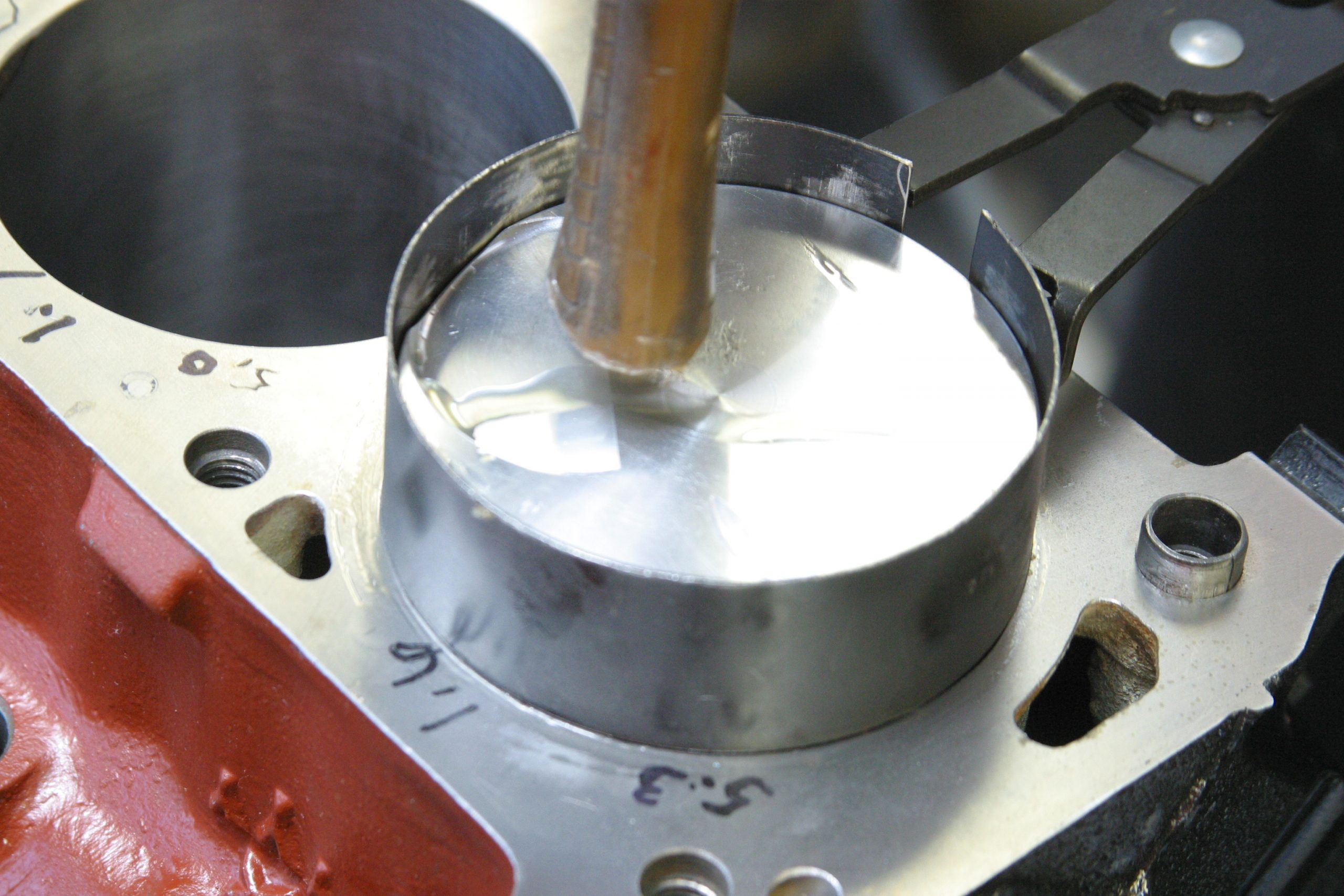
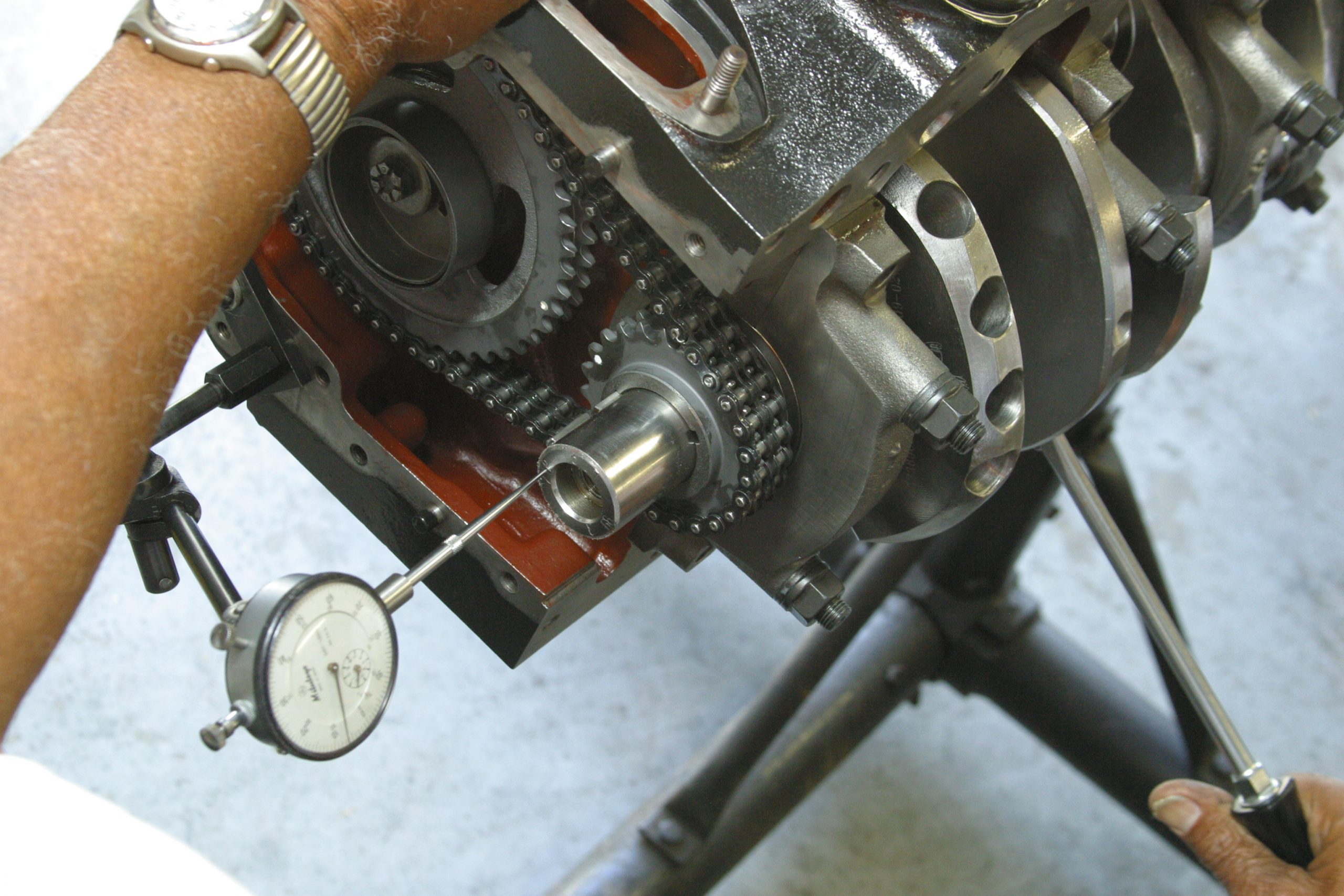
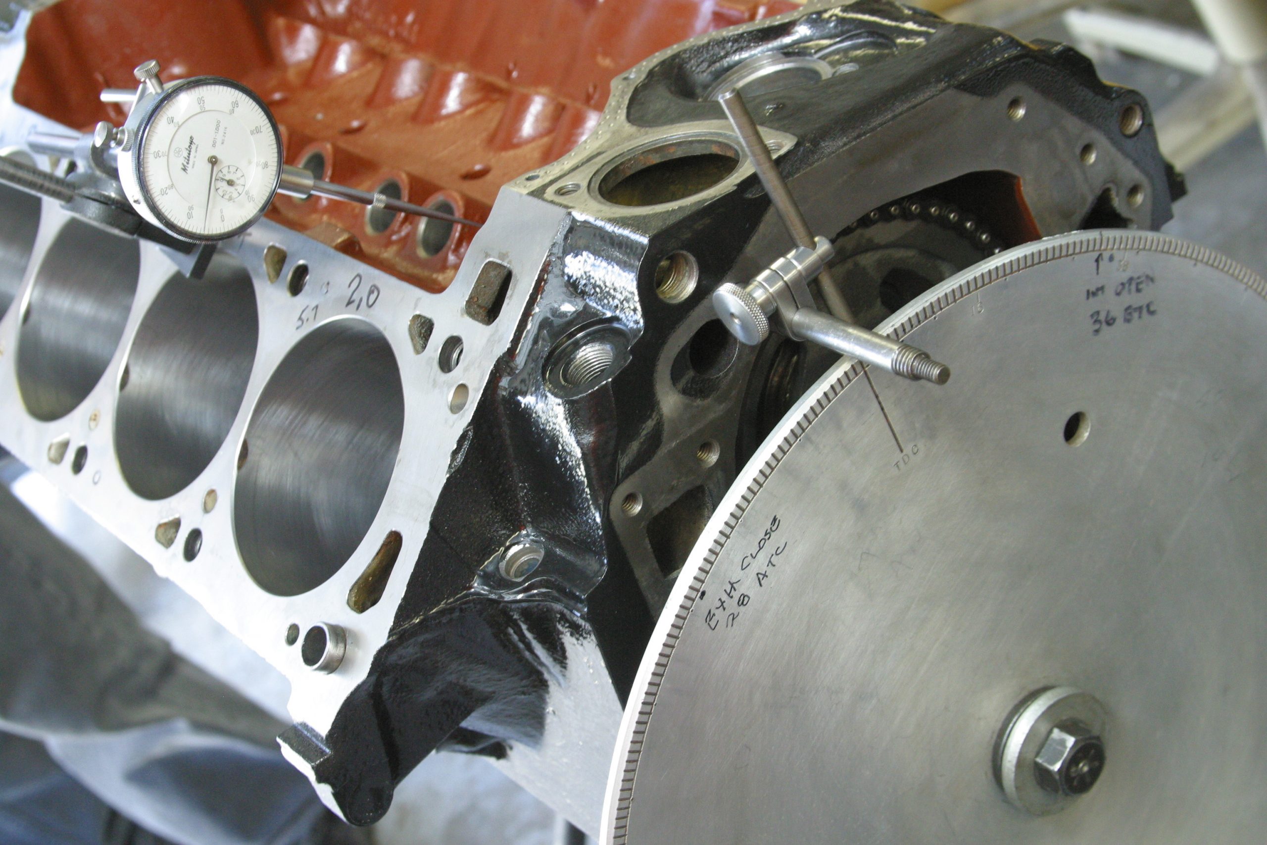
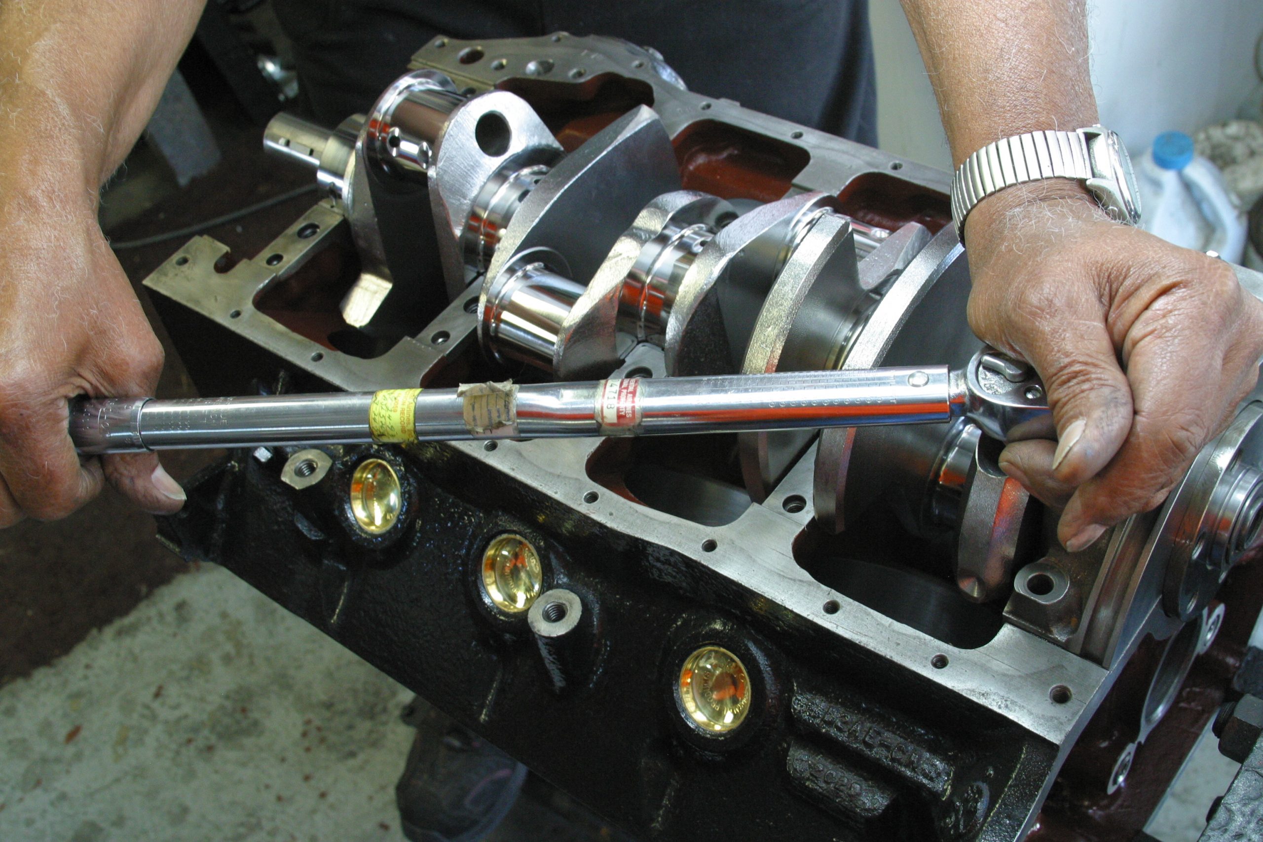
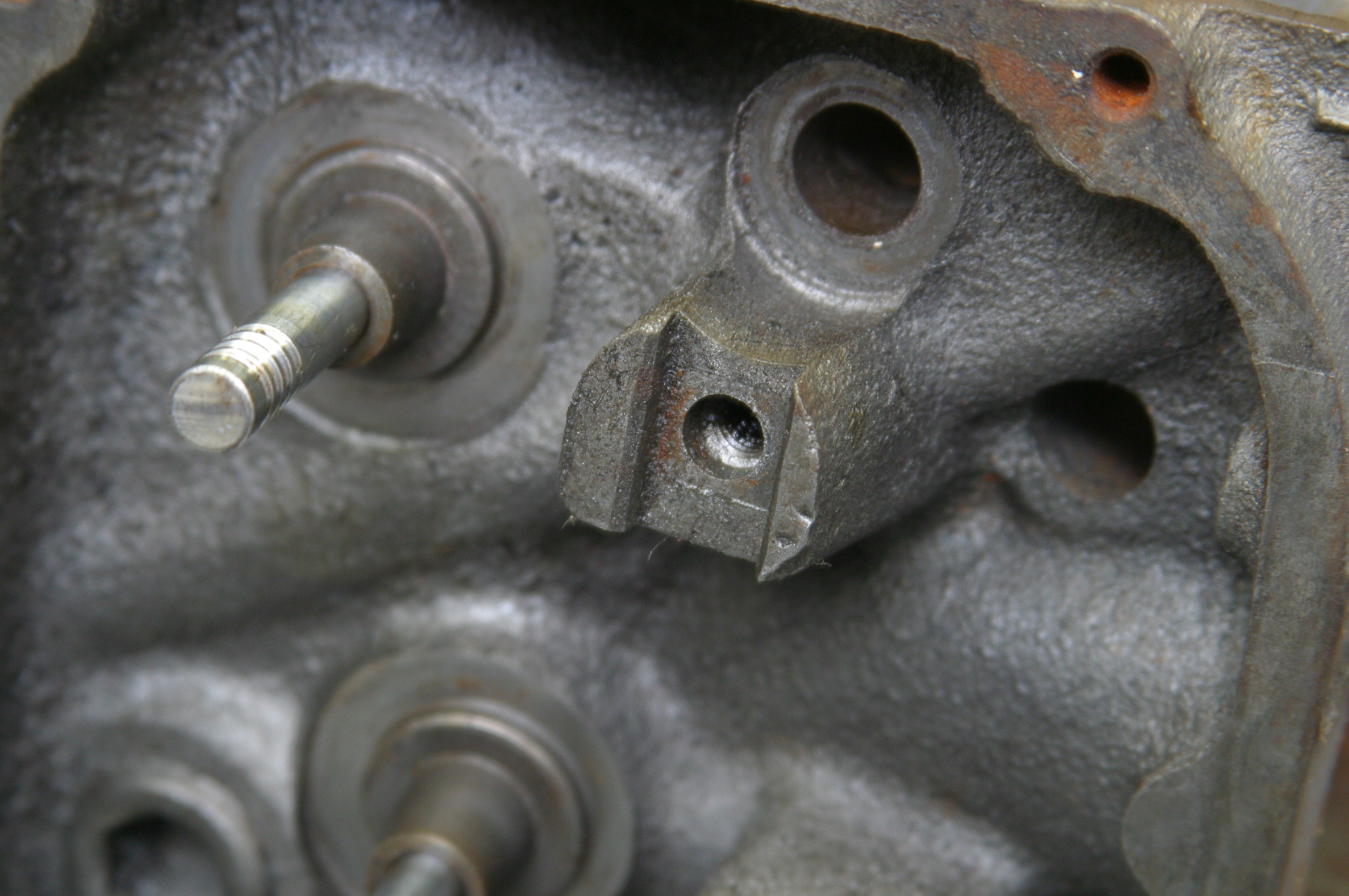
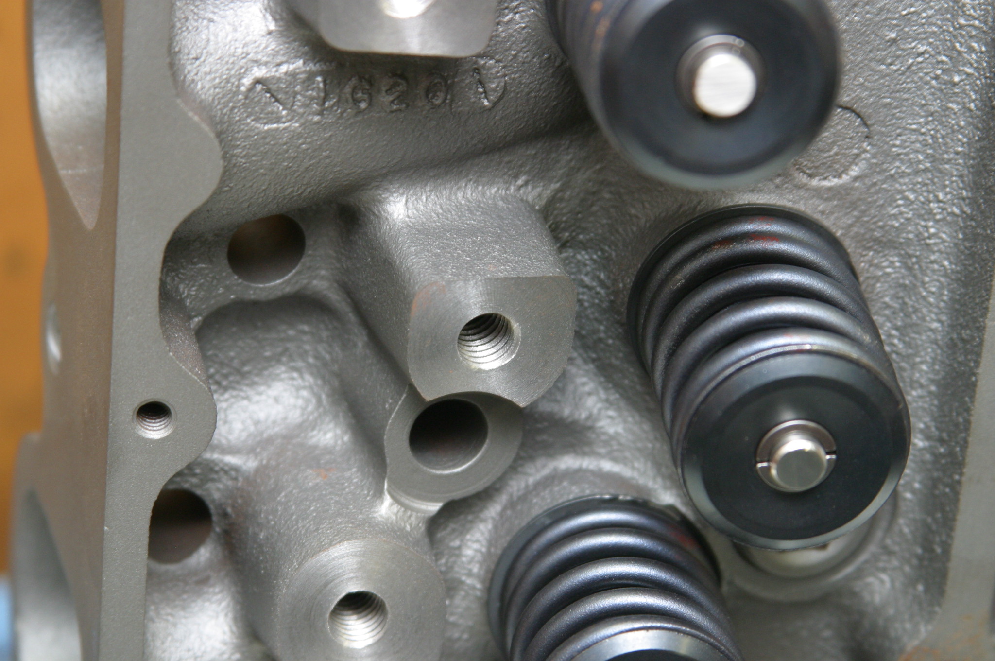
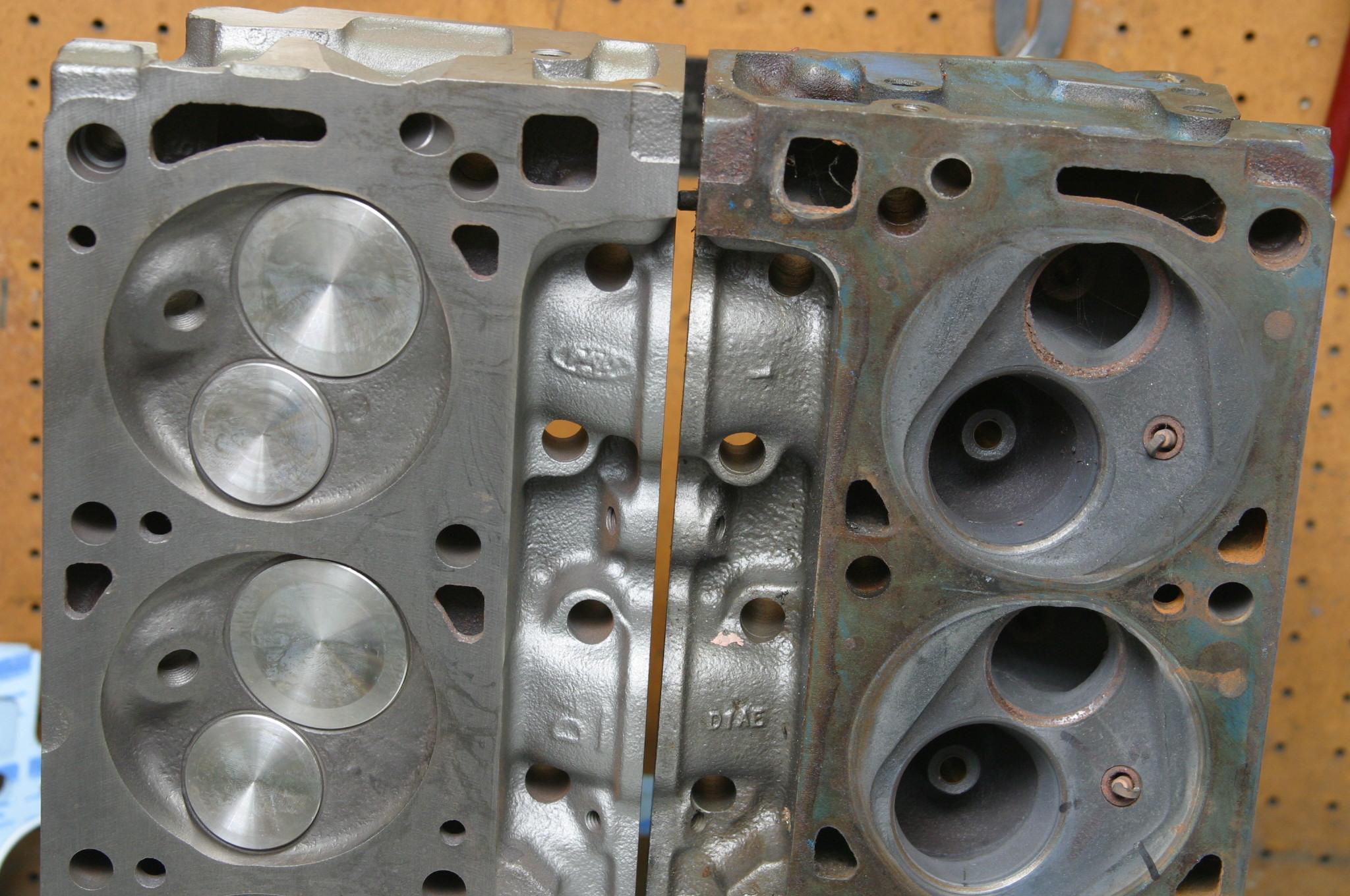
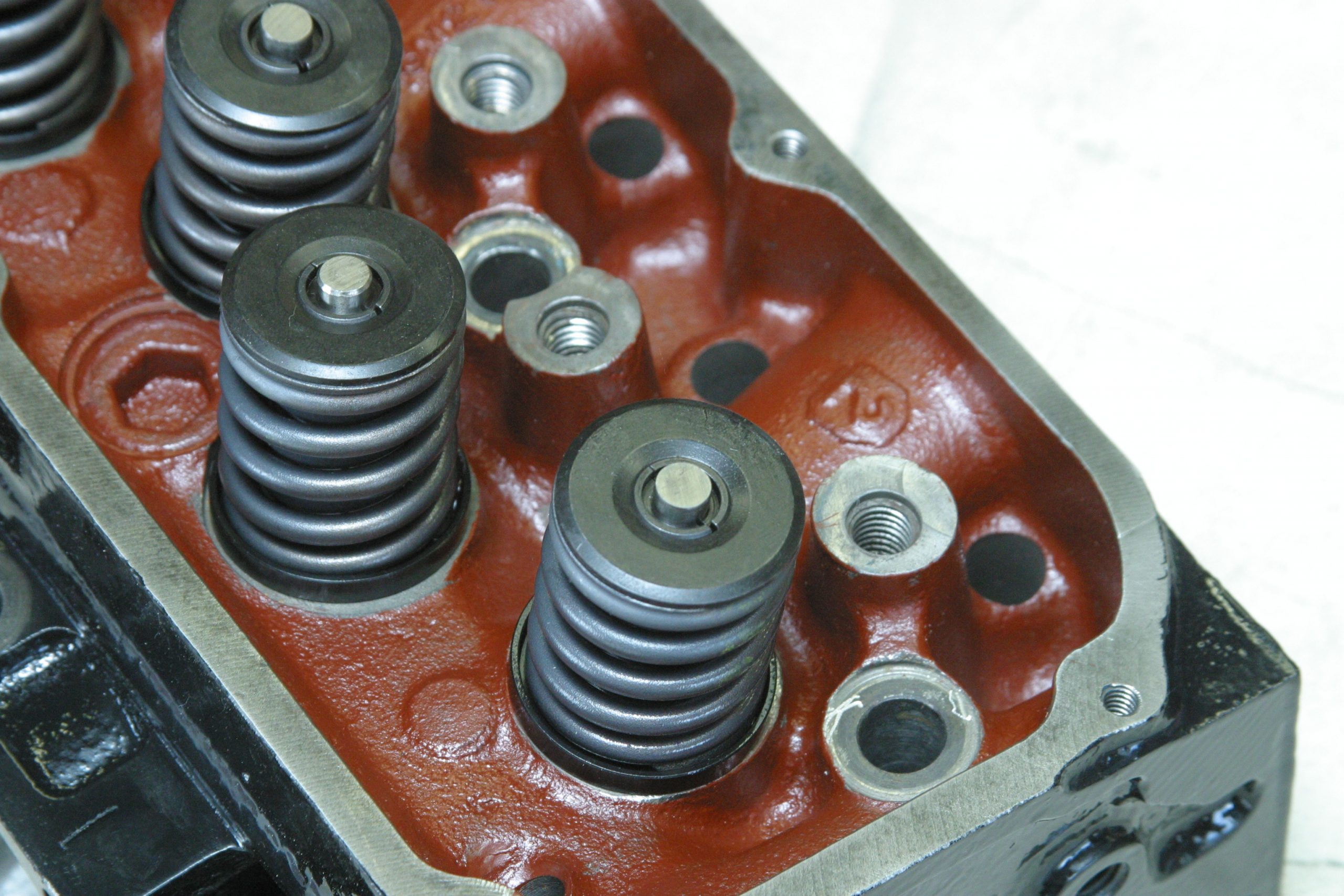
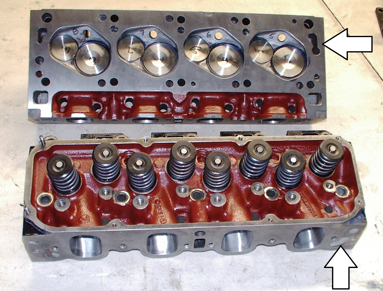
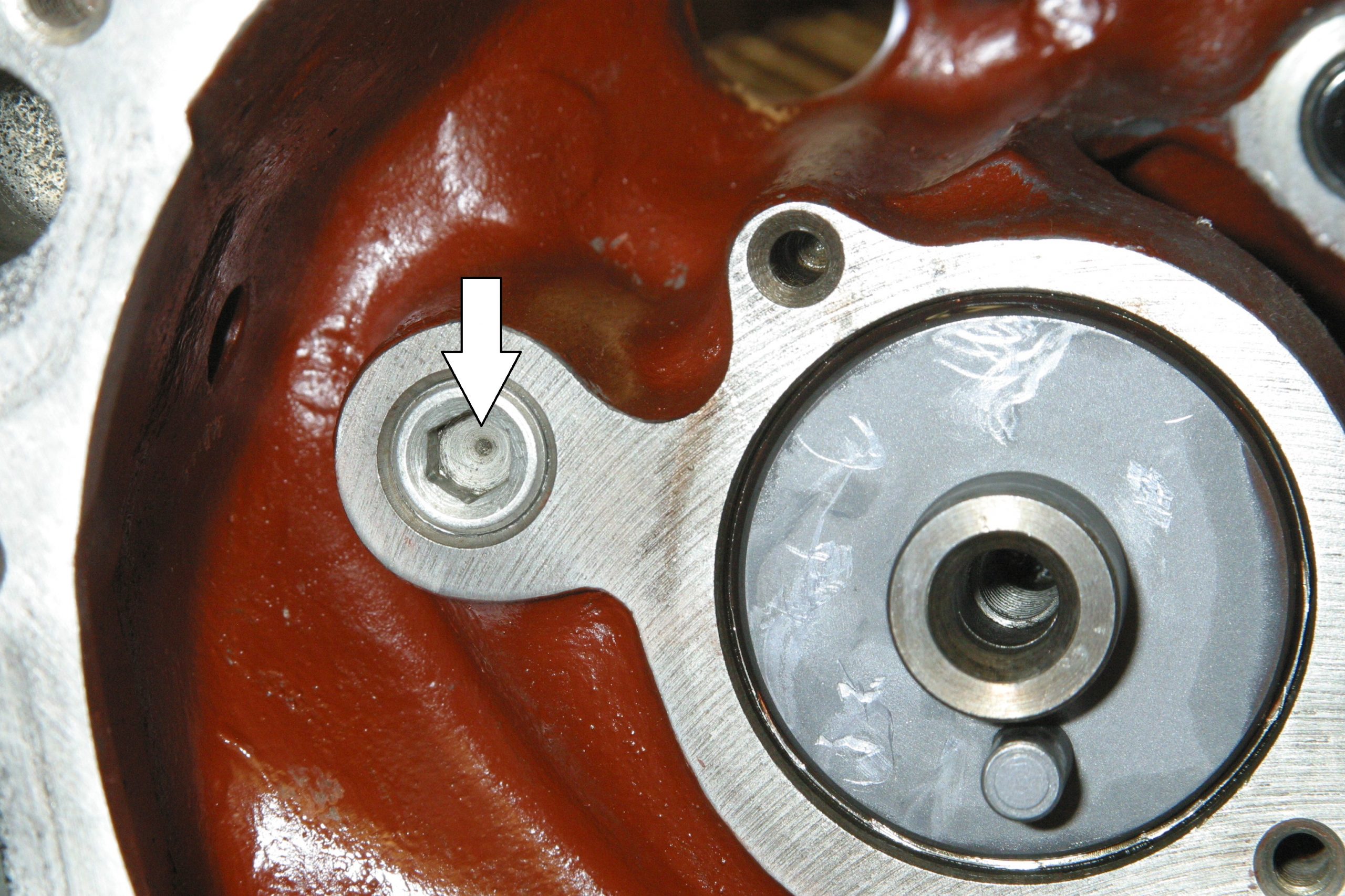
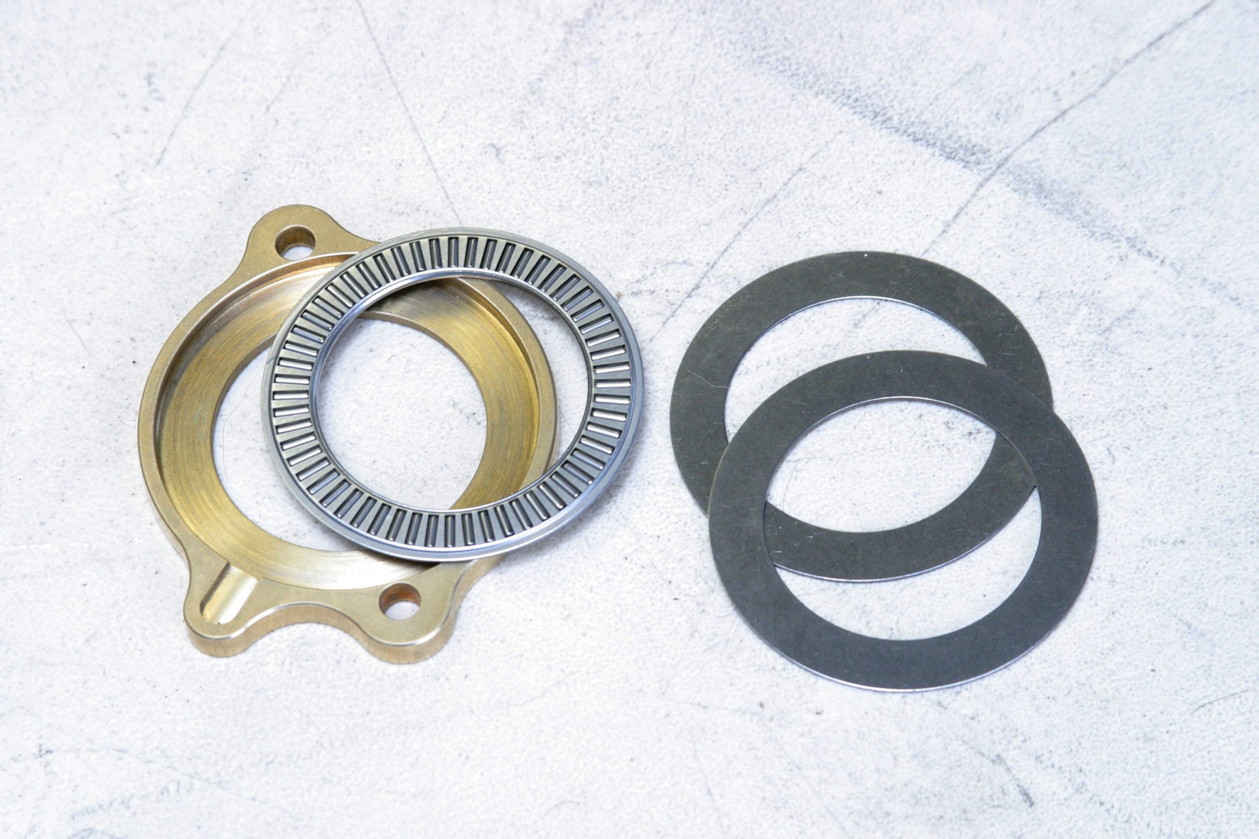
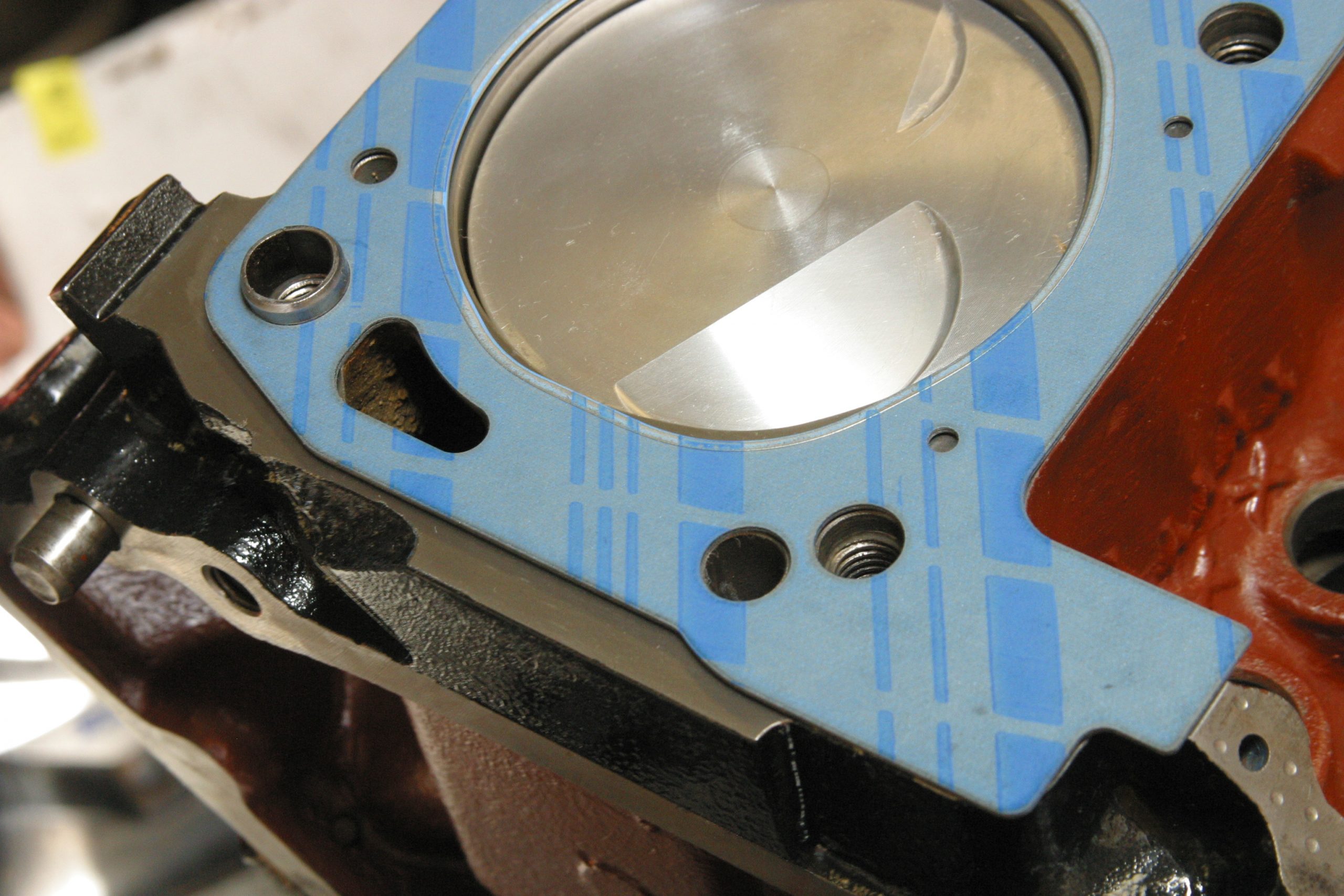
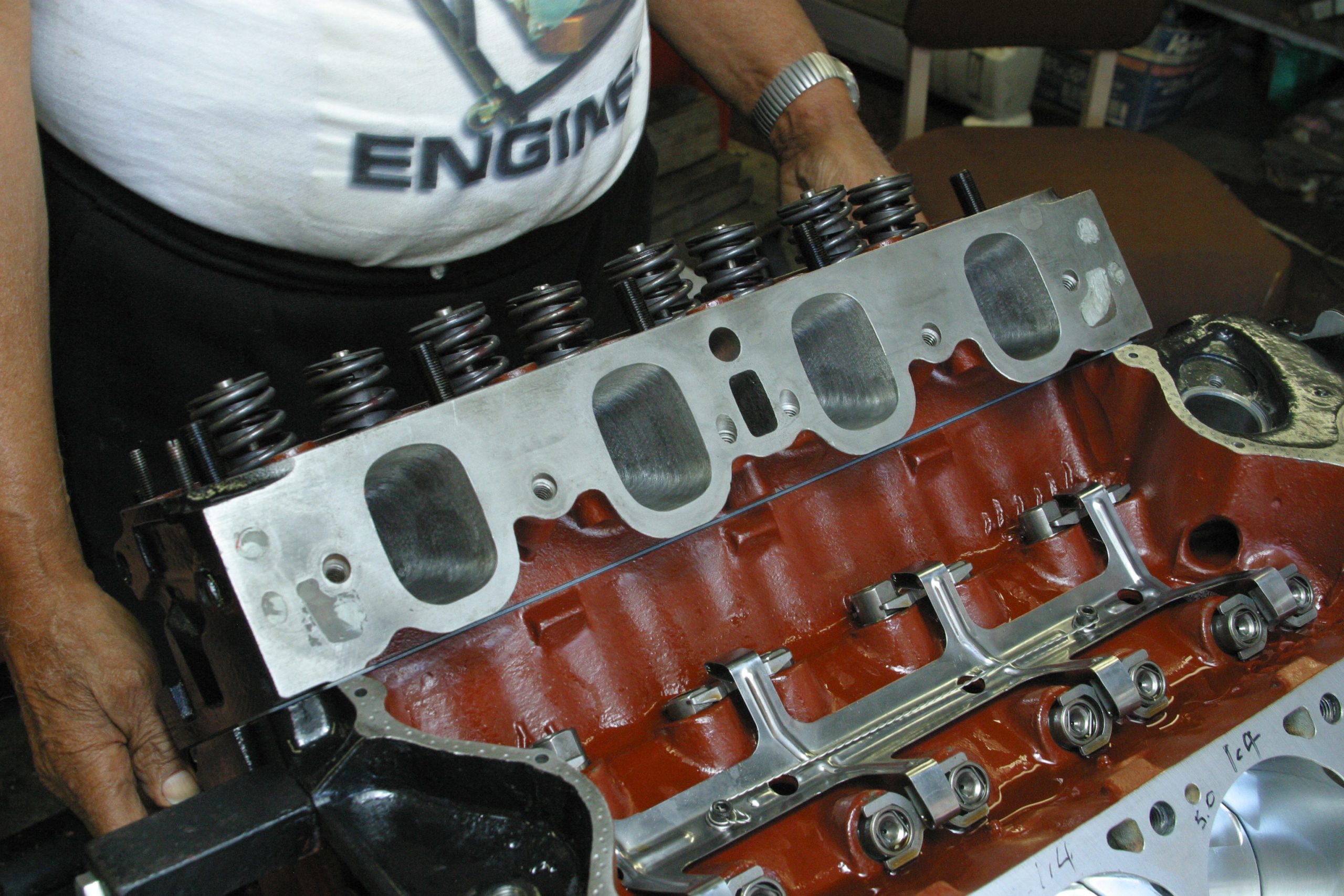
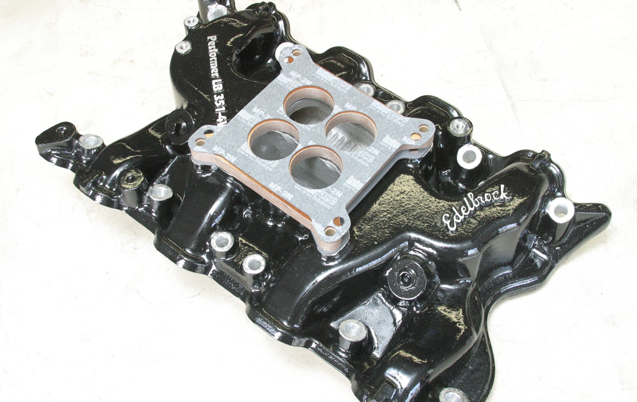
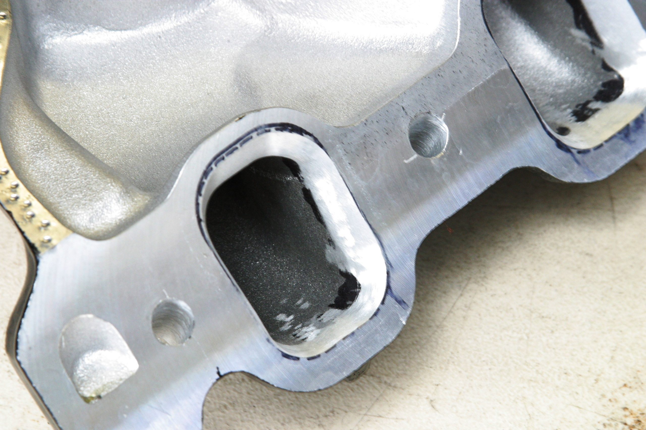
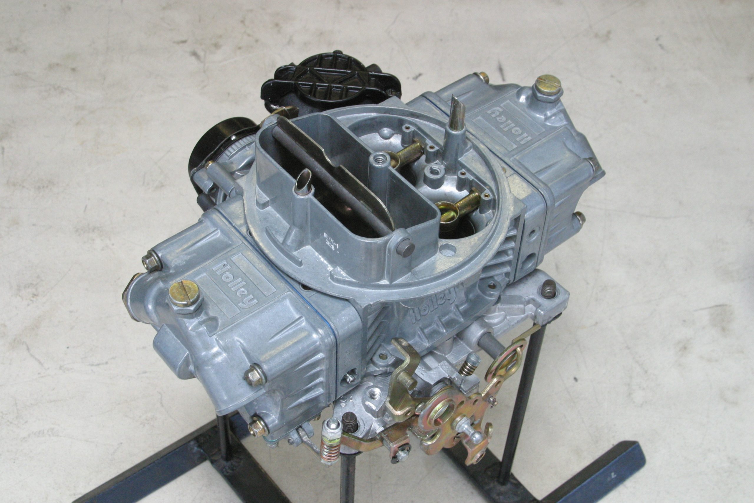
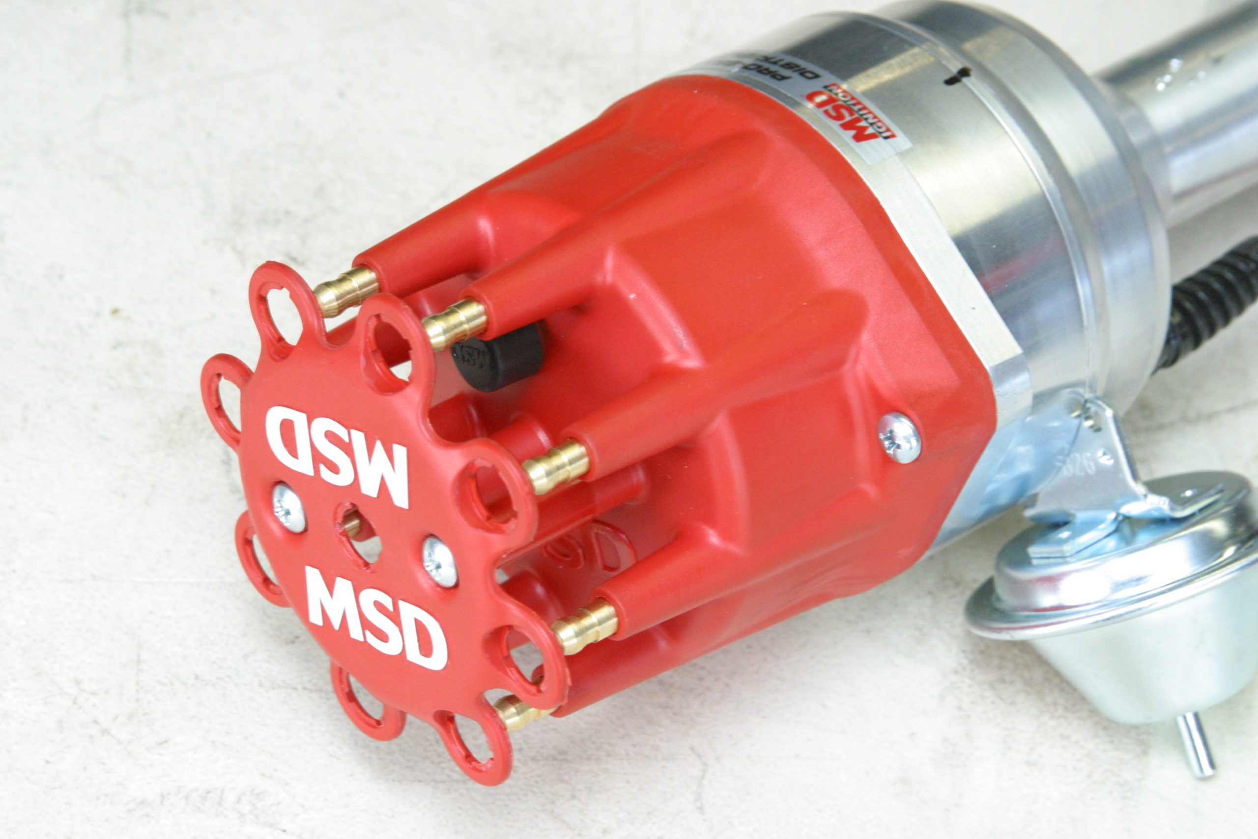
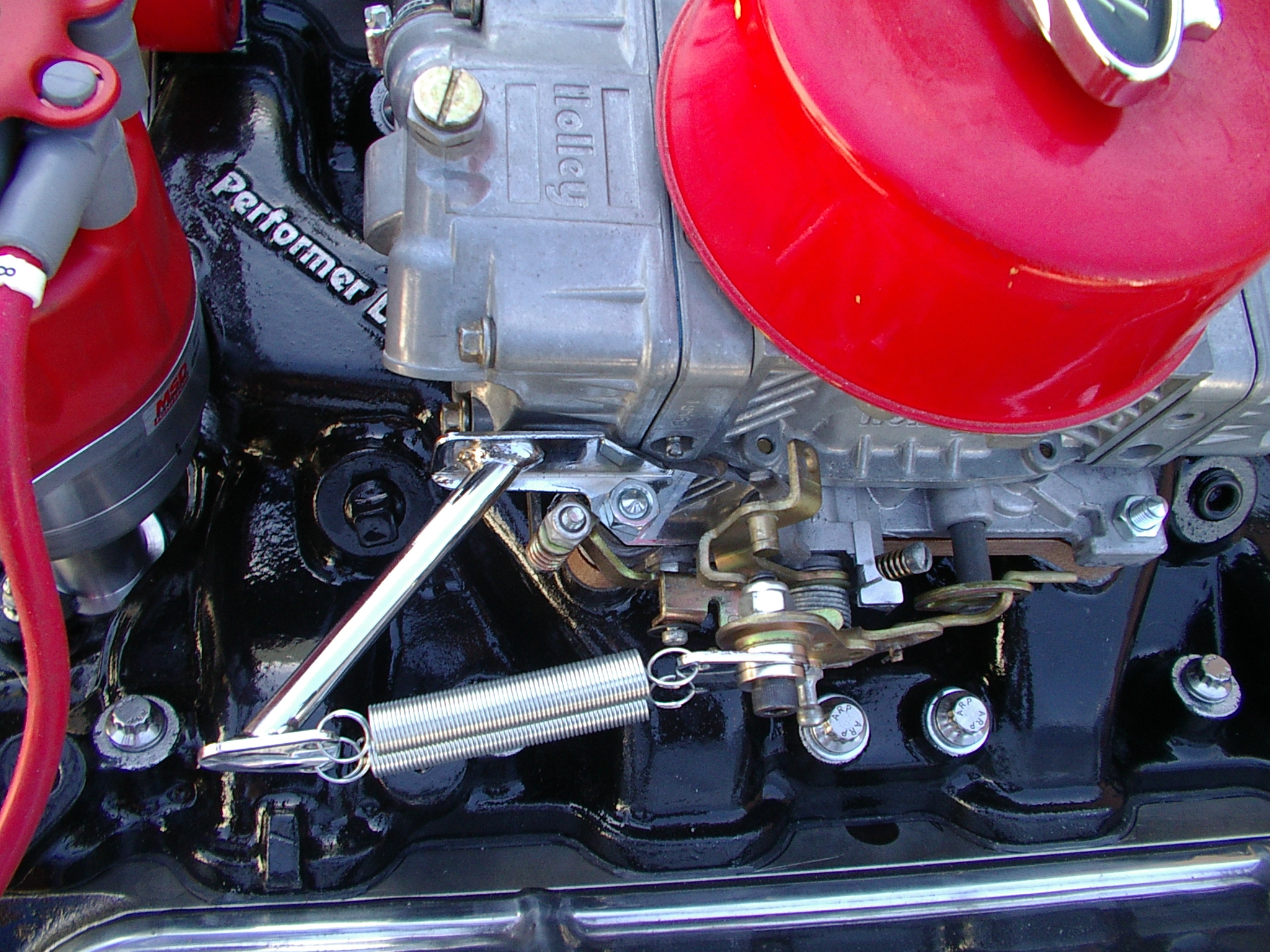
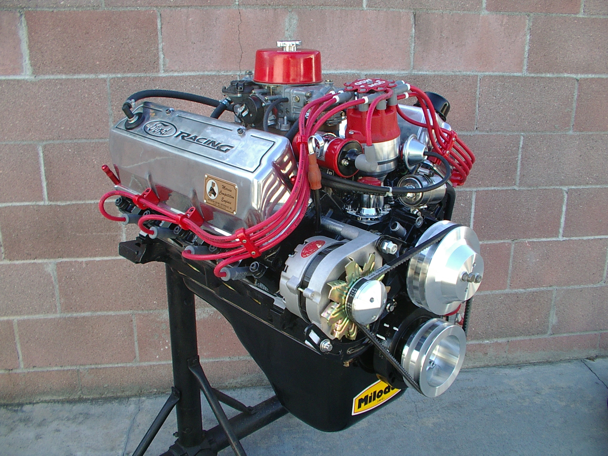
We’re working with a well-worn 351C engine. This engine was gone through in a previous build and taken to 4.030-inch bore size. MCE Engines took it to 4.040 inches. (Image/Jim Smart)With the machine work out of the way, we’re ready to tackle assembly. Marvin had methodically detailed the block including working all of the oil galleys and cooling passages. GE Glyptal has been applied to the valley to both seal the iron and speed up important oil drainback. (Image/Jim Smart)This is the desirable four-bolt 351C block, which makes it a good pick for any Cleveland project. You may also convert any 351C two-bolt main block to four-bolt mains with a Milodon kit from Summit Racing. Opt for ARP fasteners throughout for durability. (Image/Jim Smart)This brass restrictor below the thermostat controls coolant flow out of the block. Do not remove it. The 351M and 400 had the restrictor feature cast into the block. (Image/Jim Smart)Marvin has honed the lifter bores for oil control and smooth operation. (Image/Jim Smart)All 351C cranks with the 3.500-inch stroke are stamped “4M” and “4MA” for identification. The 400 is stamped “5M” and the 351M gets a “1K” stamp. The 351C and 351M cranks do not interchange. (Image/Jim Smart)The 351C D0AE-A connecting rod is 5.780-inches center-to-center. By contrast, the 351M rod is 6.580-inches center-to-center. (Image/Jim Smart)Marvin opted for the Eagle Nodular Iron 3.850-inch stroker kit (#16800030) with 6.000-inch 5140 steel I-beam rods, SRP 4.030-inch forged pistons, file-to-fit rings, Clevite 77 bearings, and 393ci displacement to give the Cleveland more street torque. (Image/Jim Smart)To get the kind of power expected, Marvin chose the Comp Cams SK32-431-8 Kit with Ultra Pro Magnum 1630-1 1.7:1 roller rockers and one-piece pushrods. Valve lift with the Ultra Pro Magnum 1.6:1 rockers is 0.566-inch on both valves on 110-degree lobe centers. Duration at 0.050 inch is 224 degrees. Advertised duration on both valves is 284 degrees. (Image/Jim Smart)Marvin stressed hospital clean in his engine building protocol. All components must be thoroughly washed and chased to ensure any debris has been removed. Marvin chases the oil galleys, cooling passages, and machined surfaces. (Image/Jim Smart)Compression ratio is more than just piston dome dimensions. All area above the piston has to be figured into compression ratio including area above the top ring and the valve reliefs. (Image/Jim Smart)Do a mock-up, even if you’re building a stocker. Make sure crank counterweights clear piston skirts and the block. The mock-up is best done without the piston rings. (Image/Jim Smart)There are at least two schools of thought on piston ring installation. Some builders like to roll rings on. Others, like Marvin, prefer a piston ring expander. Whatever you do, do not distort the ring. (Image/Jim Smart)Marvin always used an adjustable piston ring compressor. Busier shops use billet ring compressors. (Image/Jim Smart)Crankshaft endplay is checked to ensure proper fit and tracking. Endplay should be 0.004 to 0.008 inch. (Image/Jim Smart)It is critical to check camshaft specs as they pertain to the cam card. Marvin fabricated his own degree wheel and puts it to work on every build to ascertain actual cam specifications. Rarely is a camshaft per the cam card. Before degreeing a cam, check #1 piston for true top-dead-center. If true top-dead-center isn’t correct, nothing else is going to be right. (Image/Jim Smart)Torque application must be done smoothly and in one-third values. Look at the recommended torque and apply in one-thirds. If total torque is 75 ft.-lbs., apply 25 ft.-lbs. first, then, 50 ft.-lbs., then the full 75 ft.-lbs. Threads must be clean and lubricated. (Image/Jim Smart)Connecting rod side clearances must always be checked. The best range is 0.010 to 0.020 inch. Somewhere in the middle is best. (Image/Jim Smart)Marvin stressed the importance of never installing an oil pump right out of the box. Check all clearances along with pressure relief valve function. Note Marvin has safety-wired the bolts for security. A good thread locker works just as well. (Image/Jim Smart)The standard 351C cylinder head employed a bolt-fulcrum stamped steel rocker arm on 2V and 4V engines. This is the pedestal mount. (Image/Jim Smart)The BOSS 351 and 351 High Output engines of 1971-72 had screw-in rocker arm studs and adjustable rockers. You can also have your bolt-fulcrum heads modified for screw-in studs and adjustable rocker arms. (Image/Jim Smart)The 351C/351M/400 chambers side by side. On the left is the open low-compression 351C chamber. On the right is the smaller high-quench chamber you want for your 351C. You may use this head on the 351M and 400. Just watch compression ratio with the 400 and its longer stroke. You’re going to need a dished piston for the 400. (Image/Jim Smart)Here’s a close up of the head Marvin is using on our 351C build. We discovered this was a 1969-70 BOSS 302 head modified for use on a 351C. (Image/Jim Smart)Although these are 1969-70 BOSS 302 heads, they prove the BOSS 302 head is little more than a modified 351C head with the smaller wedge chamber. What makes the 351C different is a dry intake manifold void of cooling passages. The arrows indicate cooling passage modifications to get the BOSS 302 head to work on a 351C. And, 351C wedge heads can be modified to work on a BOSS 302. (Image/Jim Smart)Marvin has another trick he employs to get a more generous oil bath for timing components in front. He installs screw-in oil galley plugs, drill a small 0.020 inch hole in this one to get more oil to the timing set. (Image/Jim Smart)One very important key to performance is reducing internal friction. Full roller rocker arms, low friction piston rings, a dual roller timing set, and roller bearings where possible greatly reduces friction and power loss. These low-friction needle bearings go between the cam sprocket and block to reduce friction. (Image/Jim Smart)Marvin has thoroughly cleaned the block deck and head surfaces and has opted for a conventional Fel-Pro head gasket. He will apply Permatex’s The Right Stuff at the intake manifold joints at the heads for better sealing. (Image/Jim Smart)These BOSS/Cleveland heads have been CNC ported and cleaned up for better airflow. You can see where the cooling passages have been plugged at the intake manifold because these are BOSS 302 heads for a “wet” intake manifold. (Image/Jim Smart)Edelbrock’s Performer LB 351-4V dual-plane manifold (EDL-2665) is optimum for the street with its long intake runners and dual plane design. If you’re running 351C-2V heads, you’re going to want the Edelbrock Performer (EDL-2750) manifold for the smaller ports. Marvin has tried a number of carb spacers and settled on this one-inch spacer, which yielded better low to mid-range torque. (Image/Jim Smart)To improve flow, Marvin did a port-match to smooth things up. (Image/Jim Smart)Holley’s new Street Avenger (HLY-0-8077) at 770 cfm at wide-open throttle was the optimum choice for this 393C stroker. Marvin’s routine involved an in depth dyno test, including a jet check to confirm air/fuel ratio. (Image/Jim Smart)MSD’s Pro-Billet Ready-to-Run distributor outperforms anything you may have on the shelf. All you need to do is to install the distributor and connect three wires and the coil. The trick with any Ford V-8 is getting the distributor to seat properly, which takes patience. A maintenance-free magnetic pickup accurately triggers this ignition with increased output from the amplifier. (Image/Jim Smart)Marvin often stressed the importance of safety first. A dual throttle spring minimizes the risk of a runaway engine. (Image/Jim Smart)MCE Engines delivered a nice engine package for the money including a Powermaster alternator, front dress, and March Performance pulleys. Marvin managed 410 horsepower at 5,500 rpm and 436 lbs.-ft. of torque at 4,000 rpm making this a terrific street/strip engine ready for a Saturday night at the drags. Good for the daily commute. Nice for a Saturday night. *** Unfortunately, Marvin McAfee passed away late last year and MCE is now closed for good. (Image/Jim Smart)
Jim Smart is a veteran automotive journalist, technical editor, and historian with hundreds of how-to and feature articles to his credit. Jim's also an enthusiast, and has owned and restored many classic vehicles, including an impressive mix of vintage Ford Mustangs.
Comments
10 responses to “Building Classic Ford 351 Cleveland Power”
Who makes the lifter spider and dog bones for a Cleveland? Is it just a repurposed small block Chevy part? Are the lifters for a small block Chevy? I’d be interested in retrofiting something like this on mine instead of using link bars.
I believe Marvin used a small-block Ford spider. He’s not here to comment, but I believe that is what he used. May want to check with Comp Cams or Crane on this.
When I see 4V heads are not good the street or low end I immediately know that person does not understand 351-C 4V. Actually I much prefer the 4V on the street and for great responsive low end power. The secret to achieving that is in the cam timing compression induction carb ignition timing gearing and exhaust system. 351-C 4V are not SBC and none of the math or approach to them is the same.
Yes this set up is pretty weak, wrong cam type. All 351 Cleveland owners should read Geore Pence’s articles. There is allot of knowledge there. Google Geeorge Pence sticky #3. His specialties is Panteras
I would have to agree with that statement , if anyone looked at the valve timing on a stock
Cleveland 300 hp cam they would discover what made those heads work , and yet be suprised it made peak power at 5,400 rpm , i am currently building one for a 69 Mach 1 i am using tbe aluminum speedmasger raised port 3v head with just a light port clean up and allot of combustion chamber work mostly removing the wall around the valve seat , cam will be a Lunati roller 231@.050 112 lobe sep .610 “ 10:1 comp , port efi ,
I would love to build this motor for my 66 Mustang I have a Heidts pro-G IFS suspension so no fitment issues . The hunt for a 4-bolt 351C block begins. Think I will use Trick-Flow Aluminum Heads though
Australia didn’t get the classic small block chev in great numbers, because of a local content push by government in the 70s . The small block was in low number of imported chev cars and a fairly low volume of holden cars from the late 60s until the early 70s when the local holden v8 was released. The cleveland was imported in low numbers then produced here in more significant numbers about the same time production ended in the states, until 1983. Cleveland’s were fitted to local falcon, fairlane and f series.
Who makes the lifter spider and dog bones for a Cleveland? Is it just a repurposed small block Chevy part? Are the lifters for a small block Chevy? I’d be interested in retrofiting something like this on mine instead of using link bars.
I believe Marvin used a small-block Ford spider. He’s not here to comment, but I believe that is what he used. May want to check with Comp Cams or Crane on this.
Comp Cams has a retrofit deal for this combination.
Part number 31-1000 from Comp (https://www.compcams.com/retro-fit-hydraulic-roller-installation-kit-for-ford-289-351w-351c-351-400m.html?gclid=Cj0KCQjwvZCZBhCiARIsAPXbajsvolWJmoEhQ8__w_3jfoTRrAo75vLwzIpJOBdHgEcxojFcEnFXzB8aAsYlEALw_wcB)
When I see 4V heads are not good the street or low end I immediately know that person does not understand 351-C 4V. Actually I much prefer the 4V on the street and for great responsive low end power. The secret to achieving that is in the cam timing compression induction carb ignition timing gearing and exhaust system. 351-C 4V are not SBC and none of the math or approach to them is the same.
Yes this set up is pretty weak, wrong cam type. All 351 Cleveland owners should read Geore Pence’s articles. There is allot of knowledge there. Google Geeorge Pence sticky #3. His specialties is Panteras
I would have to agree with that statement , if anyone looked at the valve timing on a stock
Cleveland 300 hp cam they would discover what made those heads work , and yet be suprised it made peak power at 5,400 rpm , i am currently building one for a 69 Mach 1 i am using tbe aluminum speedmasger raised port 3v head with just a light port clean up and allot of combustion chamber work mostly removing the wall around the valve seat , cam will be a Lunati roller 231@.050 112 lobe sep .610 “ 10:1 comp , port efi ,
roller spider bearing any source information?
I would love to build this motor for my 66 Mustang I have a Heidts pro-G IFS suspension so no fitment issues . The hunt for a 4-bolt 351C block begins. Think I will use Trick-Flow Aluminum Heads though
Did you ever get anything going on that Cleveland? I am about to get started rebuilding mine.
Australia didn’t get the classic small block chev in great numbers, because of a local content push by government in the 70s . The small block was in low number of imported chev cars and a fairly low volume of holden cars from the late 60s until the early 70s when the local holden v8 was released. The cleveland was imported in low numbers then produced here in more significant numbers about the same time production ended in the states, until 1983. Cleveland’s were fitted to local falcon, fairlane and f series.