


An electrical system is only as reliable as its components. One easy way to increase system reliability and performance is by using relays to switch devices (lights, fuel pumps, fans, etc.) on and off. A relay is an electro-mechanical switch. An electro-magnet (also called a coil) is used to pull a set of contacts, or pins, together. You can read our earlier post on How Relays Work for a more detail description of how relays operate.
Why not just use an ordinary on/off switch, you ask? Here are some reasons why relays are better than switches:
- A correctly wired relay will provide the shortest electrical path (i.e. shortest wire length) between the battery and the device(s) controlled by the relay. Combined with the proper gauge wire, this will minimize the voltage drop between the battery and the device, allowing it to function at peak performance levels.
- Using relays allows you to control a number of devices with a single switch (a master ignition switch on a race car, for example). Having only one switch to turn off is safer in an emergency, and more convenient as well. If you’re into clean-looking systems, you can use one switch and several relays instead of a bank of bulky switches.
- Relays allow you to use the proper size fuse for each device, and to place the fuses closer to the battery.
- If you use a vehicle’s stock wiring and switches to control aftermarket devices like high-output lighting, relays will not overload or stress the OEM components. The average automotive relay can also handle a much higher current load than a switch (about 30 amps vs. 3-20 amps).
Relay Types
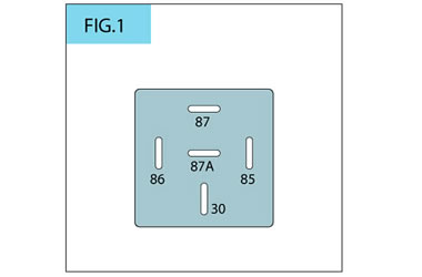
It’s important to know a relay’s pin configuration and function before connecting devices to it. Many automotive relays are similar in appearance and pin configuration and will plug into the same relay socket, but are completely different in the switching duties they perform.
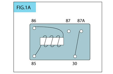
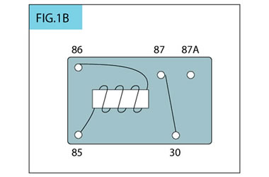
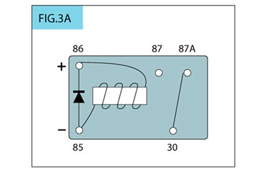
The most common type of relay used in automotive applications is the single pole/double throw (SPDT). Also known as the Bosch relay, the SPDT has a common, movable contact that moves between two fixed contacts, termed Normally Open and Normally Closed. When the relay is off, the common and Normally Closed contacts are connected. When the relay is engergized the common is switched over to the Normally Open contact.
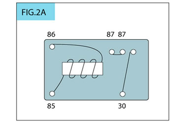
Another type of relay is the single pole/single throw (SPST). The SPST relay is often found in the wiring harnesses for aftermarket lighting; it has a common contact and two Normally Open contacts that are internally connect. When the switch is activated, the contacts are connected.
When power is removed from a relay’s electro-magnet, a high-voltage spike occurs. This spike can hurt on-board computers or other sensitive electronics. If your system has such devices, it’s a good idea to use replays with an internal shorting diode. The diode forces the voltage spike back into the electro-magnet, where it dissipates as heat.
If you move the battery to the rear of the vehicle, locate the relay/fuse bank near the battery and run 20-18 gauge wire to the cockpit to trigger the relays. If you have a master ignition switch controlling several devices (fans, ignition, water pump, etc.), but still want to use a switch for each device, you can wire the master ignition switch to those individual switches, and then to the device relays.
Relays can help you make an electrical system perform better and run reliably. That’s why you’ll find them in most quality aftermarket lighting systems and wiring harnesses. Once you use them, you’ll wonder what you ever did without ‘em!
I have a perhaps dumb question. Does it make a difference if the switch activating the relay provides a ground or power? Also, does a mix of those create problems. Often it is more convenient to provide one than the other. Thank you for you input!
Larry, generally speaking its best to control the relay through a ground if possible.
[…] to the fan would bypass the relay which is not a very good approach. Relays exist for a reason. How To Use Relays and Why You Need Them __________________ 1999 996 C2 – sold – bought back – sold for more 1997 Spec Boxster BSR […]
IAM a car mechanic and IAM interested to know how the factory fitted relays work.like which wire is from ignition switch and check which is the ground connect and which wire goes to the load.
What do you use to power pin 86? I’ve read so many blurbs on how relays work I feel like I could teach the basics in a foreign language… but no one ever talks about where you’re gettigng the juice. Thanks!
Hey James. That’s the pin that receives power to energize / de-energize the switch. You’ll need to power it with (in a typical automotive application) 12 volts–most often the vehicle battery.
That way, you can wire “pin 86” to receive voltage from (for example) the vehicle’s ACC switch, so when you turn the key to the ACC position, the relay will energize and switch to the alternate pole.
Make sense? Respond back if you’d like clarification.
If I have multiple relays for multiple lights should they be fed from the battery separately and each have a fuse or can I jump them from each other
It all depends on the current draw of your lights. You can string along several interior cabin LEDs and not pull a lot of amperage, or conversely, a pair of high-output off-road lights could draw a significant amount of current. If you’ve got multiple high-draw applications, you’ll probably want to add a distribution block with a fuse block and run a dedicated and individually-fused feed for each set of lights. Regardless of what you choose, it’s of utmost importance that your wire gauge (AND relay rating and fuse value) is appropriate for the run length and amp draw. If you’re referring to the relay’s switched voltage line (pin 86 in the the dia. above) you can run a single wire to each, as it’s low current draw–good if you want to energize a group of relays with, say, your ignition key.
I ran into a problem. I’m pretty sure I wired up my relay correctly. But it’s not turning on my electric water pump. Only problem I’m seeing is my key wire is only putting out 9v instead of the 12v. Would that stop my relay from not working?
What kind of car do you have? Some manufactures use low voltage circuits after the main fuse box for triggering everything inside the car. You may have to run a micro relay from your current “key’ed” wire to the battery to get a 12V circuit. If that is what you need.
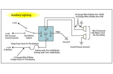
Hello, I am looking to install some LED spot lights on the back bumper of the truck. I want to run them from 2 switches (through relays). 1 switch control will be the reverse lights. The other switch will be a manual switch on the dash so I can turn them on when needed without having to put the truck in reverse and setting the parking brake (not very safe).
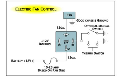
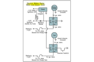
I’m looking at your diagram showing the electric fan control. Essentially I am doing the same thing, just a different load. Also instead of the “Thermo switch”, I will use my factory reverse light as a trigger. My question is; how do I prevent back flow of current from the dash switch to the reverse circuit? Do I need to even worry about this? I’m not worried about the (factory) reverse light coming on arbitrarily. I’m just worried about the current going beyond the reverse light into the fuse box/computer/etc.
Use diods to prevent flow in the opposite direction. Diods are like check valves for electricity
Can use a machine that does not use relay to make it use.
i have an
’88 ford festiva L. under the hood are 3 electrical relays in a row: 2 “browns” with one “red” in betrween. the red indicates “main”
the left brown indicates ptc and the right brown has printed, “head”.
i can run the car with only the middle connector and wonder why i don’t need the other 2 and what do they represent?””””””””””””””””””””””””””””””””””””””
[…] Want more information about how relays work? Read this, Relay Case: How to Use Relays and Why You Need Them […]
I am asking a “General” Question dealing typically with Street Rods, Most of the Time I get a Harness Kit from a Supplier, What are the Guidelines for using relays? In Other words, If the Car has an Electric Seat!!?? Only One. OR an Electric fan? Electric Fuel Pump? Sometimes the “Kits” may not specifically dedicate a “Circuit” for that, I am “Guessing” at the Amp Fuse to use, I.E. typically I Use 30amp Fuse for Electric Radiator Fan, Electric Fuel Pump, Headlights BUT how about for the Electric Seat? Only ONE seat!? Thanks VERY MUCH for an Email reply!
I have several 30/40 amp spdt bosch style relays, what is 87a used for?
Can not using a relay cause a fire ?
I added a Bosch Style relay (for anti-grind) to my ignition harness wiring while putting in my Remote Starter (“R/S”). Everything worked fine until I installed this relay. Now the vehicle won’t start, even using my factory key! I know I installed the relay correctly (at least, as per the R/S instructions); however, based on everything that I’ve read about how these relays work (including the above), I don’t see how the vehicle would start based on how the instructions told me to wire this. Here are the details followed by my specific question(s):
Vehicle: 2006 Camry LE (2.4L 4-cyl)
R/S: Crimestopper RS7-G5
Bypass Module: DEI 556u
Note: Vehicle’s 12v STARTER WIRE (at Ignition Harness) was cut and connected to relay per below.
PIN 30: connected 12v STARTER OUTPUT #1 (12 AWG)(Starter Side)
PIN 87A: connected 12v STARTER OUTPUT #1 (Ign Switch Side)
PIN 85: connected to YELLOW/BLACK OUTPUT from R/S unit (18 or 20 AWG)(Ground Out When Running)
PIN 87: not used (connected to nothing)
PIN 86: connected 12v IGNITION OUTPUT #1 (14 AWG)
Additional Notes: the Anti-Theft Bypass Module Blue Wire is connected to the R/S Yellow/Black Wire before the PIN 85 connection. And the R/S High-Current Starter and Ignition Wires are connected to these same Vehicle Starter/Ignition Wires before the Relay on the Motor Side.
When I turn the key, it sounds like it’s trying to start but can’t.
My question is:
How can the STARTER OUTPUT #1 WIRE (from the vehicle), which I cut and ran through the relay, still possible work as it was originally intended (by Toyota) based on this wiring?
It would seem to me that the 85 PIN basically wouldn’t be grounded to anything if I’m using the key (because it’s connected to the R/S which isn’t doing anything). And, when I crank the Ignition Switch with the key, wouldn’t the relay send power to that 30 PIN, thereby triggering the switch from the 87A PIN to the 87 PIN (which is connected to nothing)??
One last general question is, which of the 5 pins on this relay are considered inputs (85 and 30?), and which are considered outputs (86, 87 and 87A?)
Someone please help me with this. I could just take out the relay, but I’d rather understand what’s going on.
Chris,
First answer to your question about Starter Output. The reason it still works is because Pin-30 is normally closed to Pin-87A. So even though you spliced the starter wire into the relay its path is normally closed, therefore power is still flowing between both pins.
Answer to second question, when you turn the key to run, the relay sends power form Pin 30 and switches power from Pin 87A to Pin 87. So i think your issue is you need to move the wire from Pin 87A to Pin 87.
So here is the pin configuration.
Pin 85 is ground.
Pin 86 is switched power.(ACC/RUN/START)
Pin 30 is constant power.(12V)
Pin 87 is output load. ( wire feeding Starter)
Pins 85, 86, & 30 I would consider inputs.
The only outputs are Pin 87 & Pin 87A which feeds your load.
Chris,
Does the remote start unit have a separate wire for ground? If not, then you need to actually ground the connection from Pin 85 and the yellow/blk wire from the R/S to ground. I forgot to add this in my previous comment.
I want to wire in a Relay for my off road lights. I read that running a fuse on the power and control side is best. So I bought a relay with a built in fuse. So my wiring would go like this.
30 fused 12 volts
85 Ground
86 Trigger wire fused
87 To LED Lights fused
My two questions are the fuse built into the relay which side does it protect? Also how would you wire it to be switched ground?
Does the relay have to be as close as possible to battery or can it be say 20’ away?
So a relay is energized by a switched 12VDC+ (eg acc)Since that source is switched (the ignition must be on), why use a relay at all? How about just using a fuse block (like https://flic.kr/p/2h2QAir), and using the switched 12VDC+ as a power source for the fuse block?
I live in OZ(Australia) Victoria. I have an Ol’ 1971 Dodge Ozzy built RHDrive -Ute/Pick up as you Americans word them, an AT 4, C1100 which I’m trying to complete its been an 8 yr part time project. Its a V8 L.A. 318 Chrysler motor with 3 speed auto transmission.
Last year I bought Cole Hersee 2 speed(hi/lo) wiper/ washer unit. It’s part number is 75228-03. It has 6 pin configuration. L-LO, H-HI, W-WASHER, B X2- BATTERY & P-PARK. I’ve found a place to the left of the steering wheel under the dash to install it- however not complete regarding the electricals.
Its been a little difficult trying to get the right information specific to the car & correct installation details along with trying to get the right relay(s) to reach a compatible & effective combination to complete this part. There are no installation details nor is it easy to find a video you tube clip for this application. Mind you all the wiring is Yellow in colour from the washer unit. At least I have been able to clean the wires & could find that they were printed on close to the terminals ie: 71-4, 71-2, 71-1 I could not see a 71-3 anyhoo I’ve managed to isolate them & get the right combination to work just from the car battery.71-4 Hi speed, 71-1 Lo speed, 71-2 could be park-not sure & the other wire going to ignition without any marking other than yellow/green elect. tape wrapped around it.
If you google the following this has been one of the best illustrations for me to match up with the C/H 2 speed unit.
https://lotusmarques.com/images/lm/Europa-wash-wiper-switch-wiring-diagram/europa-wash-wiper-switch1r-wm.jpg
As you are very savvy in the auto field I thought I’d ask if you may be able to assist. I’ve been able to get the wires from the wiper unit to work(Hi/Lo speed) along with the H2O pump to emit water onto the windscreen. That’s not the issue. Its trying to figure out the correct relay(s) that may be required. I have a few Bosch Relays (12VLT 30A Part no. 0 332 019 150) lying around with the following configuration 30, 85, 86, 87 & 87(NOT 87A). Would these relays be fine to use or could you recommend another constructive method?
I sure would appreciate your help as I believe I’m about 65-70% there I just cannot come up with the right combination. I have a 30A circuit breaker & inbuilt fuses to safe guard the wiring as I’m testing them along with a Toledo circuit tester with inbuilt light. I’m close but not close enough & have tripped out the circuit breaker on a few occasions. I know how to not do it correctly that’s for sure! Just like to rectify this last stage once & for all.
As I live in regional area of Victoria-postcode 3875.
Hear from you when convenient.
Thank you & kind regards Rupert from Oz.
Does it matter how many amps the switch is rated for if I use a relay?
I am currently working on a 1953 Desoto and a 1954 Kaiser.
What deviations (if any) from the instructions you have provided here have to be made when dealing with:
(A) a six (6) Volt negative ground system?
(B) a six (6) Volt positive ground system?
I want to connect my digital radio APX6500 to klaxon and strobe light to be active when the radio receives an emergency call
In the back of the radio, I connect to pin#7 that will sense the EMERGENCY call.
If you have the product, then I’m willing to purchase a good number of the solution to be deployed across my agency
Regards,
Question – can I use the positive side of the coil to power up an electroic fuel pump ?
I have a spst relay. I would like to use it like this and I would like to know if this is possible. I want to run everything off of the relay including my amplifiers as well as the aftermarket stereo how would I hook this up using a four-pin single pole single throw relay
If I understand your setup correctly, you’d simply wire it like this:
1 pin goes to chassis ground (85)
1 pin goes directly to the battery + (30)
1 pin goes to the bus with your accessories (87)
1 pin goes to the switch, presumably on your dash (86)
…
BUT, it sounds like you may be running a high-power sound system, so make sure your relay and wire gauge can handle the amperage (current) your system will draw, measured in amps.
…
This post may be another good resource.
Should a headlamp relay be sited near the battery or near headlamps?
Hey Ian, I did this mod to my old Jeep a while back and the pre-fab harness kit I used had the relays wired near the bulbs. In fact, I bolted both relays to the backside of the Jeep’s grille.
…
Electrically speaking, it makes sense to have the shorter electrical path between the relay and the bulb, rather than the battery and the relay, as the parasitic loss would make more of an impact on the power supplied to the bulbs (provided there’s enough voltage to trip the relays to begin with).
…
You can read my headlight relay walkthrough here if you’re interested.
[…] Relay Case: How to Use Relays and Why You Need Them … […]
[…] More items… […]
I am thinking of using a 12V 250A Continuous Relay On/Off 5-pin Power Switcher Relay to kill power to a radio & 600amp amplifier. I need something to protect small contacts of switches used to swap Bass & Treble sounds for rear passengers between ones on the package tray and the back of the front seats.
My question are: will a Micro Snap switch be able to handle to Amperage necessary for the 15 seconds I presume a driver will need to toggle the speaker/sound direction. I presume the power is only required to maintain the ‘Open’ position.
Thanks in Advance DaveW
[…] More items… […]
Hello David, can I please ask your advice on relays. I am working on a pre-war 12 volt (original system) positive earth Austin.
It has the single filament headlamp bulb with a solenoid controlled dip mechanism which I want to retain.
Question is can I fit a common 5 pin Bosch relay to the headlamp wiring ? I imagine the pair of individual lamp solenoids consume increased power.
I am replacing the old and dangerous original wiring that feeds the headlights, side lights and brake lights with new modern wire.
It is my intention to keep the car as original as I can which includes keeping the positive earth system.
Should it be possible to use a relay on the positive earth system what would be the wiring procedure to the relay.
With negative earth I know it is 30 to + on battery, 85 to earth, 86 to trigger ie dip switch and 87 to consumption unit ie headlights but would be fearful to use this application on reversed polarity.
Your reply will be very much appreciated.
Thanking you Eugene in Northern Ireland.
Hi folks. I have two questions.
1. I’m converting my on-board air compressor to a mobile unit and not sure how to wire up the 4 post relay and toggle switch to power. I want run the power through jumper style cables. Do I connect the wire coming from Post 86 on the relay and the accessory ground together to the alligator clip? Do I connect the power wire from relay post 30 and the power coming from the switch together to an alligator clip?
2. Can you use a 24 V resettable fuse on a 12 V system? instead of using a 40 amp blade maxi fuse on my conversion I have a 50 amp resettable fuse that I’d like to use if I can but it’s 24VDC.
Is a combiner the same as a relay. I was wondering if I can put my relay between battery and 12 v air conditioner. Will this
automatically turn off when solar panels quit working in the evening.