In Part 1 of our 540 cubic inch big block Chevy build, we covered prep of the Dart Big M block, balancing and installation of the Scat/ICON reciprocating assembly, and installing the COMP Cams solid roller camshaft and timing gear. All good stuff.
In Part 2, we continue the build with the oiling system; installing the Dart Pro 1 cylinder heads and Harland Sharp roller rocker arms; and a Dart rocker stud girdle. We also checked piston to valve clearance and measured for proper pushrod length.
In Part 3, we’ll wrap up our project with the installation of the induction and ignition systems, headers, and other parts like the harmonic damper and electric water pump. Then, we go to dyno and show you how powerful our 540 is. That’s good stuff, too.
If you’d like to see the other stories in this build series, check them out here:
Oil Pump & Pan
We chose a Melling high volume/high pressure oil pump for this build. The pump body is CNC machined from 6061-T6 billet aluminum and has an integral pickup screen to keep the pickup from loosening. Features include smoother oil flow and less internal drag as compared to conventional pumps; billet spur gears; a chromoly driveshaft with extended support; an adjustable pickup screen; and multiple pressure settings. Another very nice feature are machined stand-offs at the bottom of the pump body surrounding the screen area. They prevent smothering the screen in case the pan sump ever touches the pump.
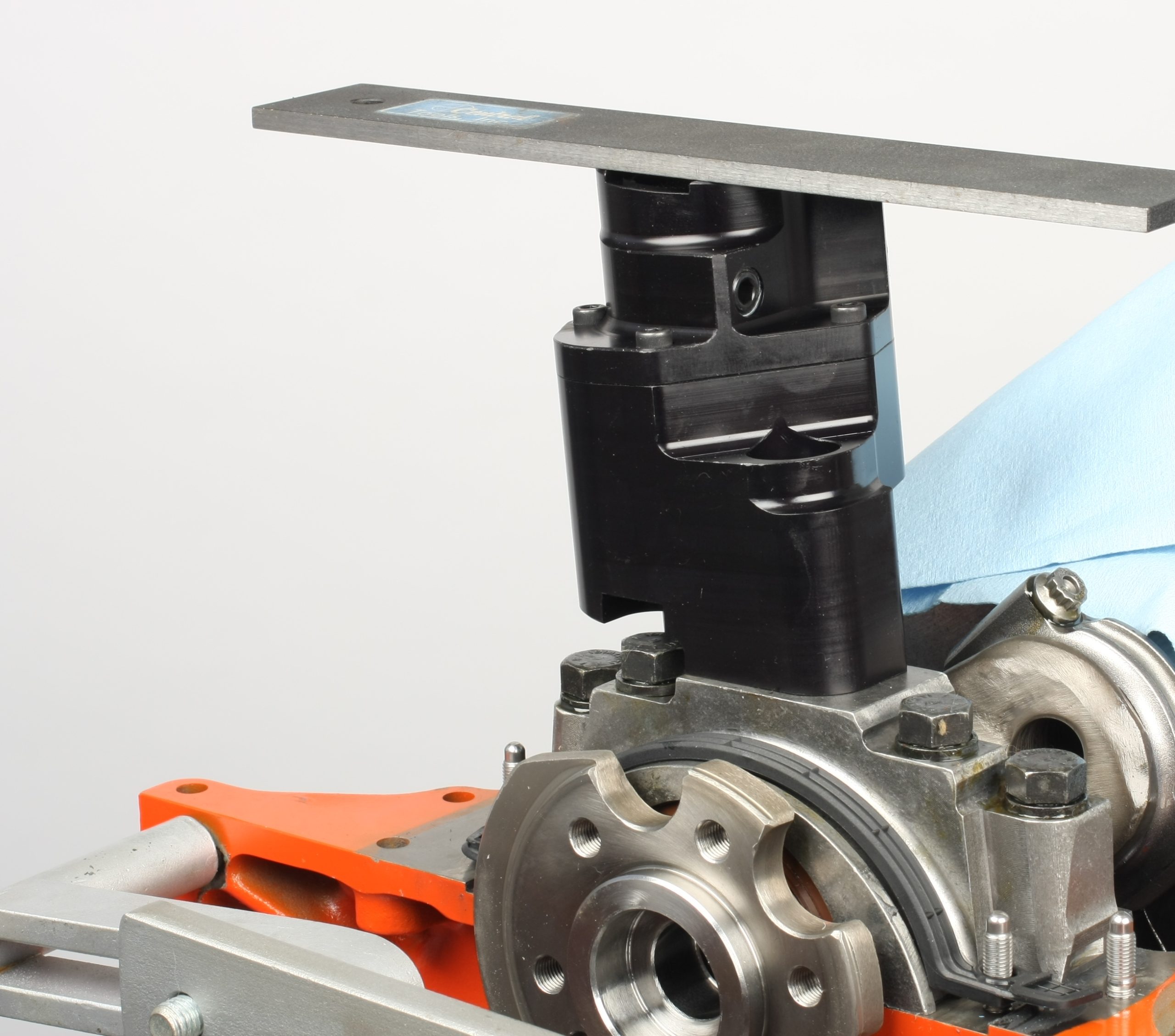
The Melling oil pump requires an oil pan with an eight inch deep sump. The pump includes a mounting stud and nut, but I opted to use an ARP pump stud as it features a female hex that is handy for installation or removal.
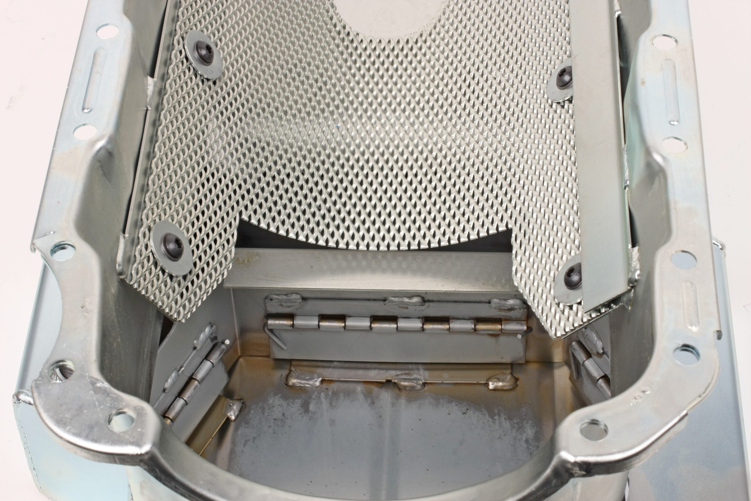
Suitable for street, drag or road race use, the Moroso steel oil pan has the required eight inch deep kickout sump and a sump capacity of 6.5 quarts. The pan can handle Stroker cranks up to a 4.250 inch stroke. Features include a trap door baffle system, windage tray and crank scraper; and a 1/4 inch NPT dipstick bung located on the right side of the pan.
During test fitting, I checked for oil pump to pan sump floor clearance, Block pan rail to pump bottom measured 7.750 inches. Adding in a 0.100 inch crushed oil pan gasket, total pump to sump clearance was 0.350 inch.
The only glitch I ran into involved a clearance issue between the oil pump and a baffle in the lower rear wall area of the pan sump. The pump contacted the baffle, preventing the pan from moving rearward for proper bolt hole alignment. I trimmed the steel baffle to eliminate the contact. In fairness, Moroso designed the pan for a stock-style pump, which would have cleared just fine.
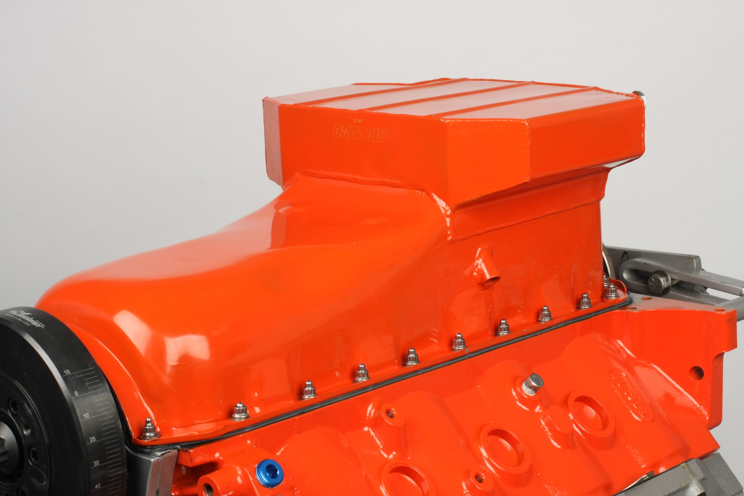
The Dart block instructions call for a four-piece Fel-Pro oil pan gasket set. This gasket does not fit our Moroso oil pan as the rail mounting holes don’t align with the holes in the gaskets. We used a Moroso one-piece oil pan gasket which fit perfectly. The thick rubber/silicone gasket features a stainless core to prevent overtightening. I added a dab of Permatex Optimum RTV to all four corners prior to positioning the gasket and the pan.
I secured the pan to the block using ARP stainless steel studs. I installed the studs into the block rails hand-tight with Loctite 242 medium strength thread locker. The nuts were torqued to 12 ft.-lbs.
Lifters
Our solid roller lifters are Morel Black Mambas. They have a 0.842 inch OD billet steel body and are 0.300 inch taller than the stock Gen. VI big block lifters. This is required to accommodate the taller lifter bores in the Dart block. Summit Racing carries Howards Cams RaceMax solid roller lifters that are a great alternative to the Morels.
Cylinder Heads
We chose Dart’s Pro 1 CNC aluminum heads for our 540. The CNC-machined heads have 121cc combustion chambers with 2.250 inch intake and 1.880 inch exhaust valves; 325cc intake and 129cc exhaust ports; and 1.625 inch diameter valve springs rated to 0.850 inch of valve lift. The intake ports are in the stock location and the exhaust ports are raised 0.300 inch from stock. Other features include manganese bronze valve guides, lightweight titanium retainers, and 10 degree valve locks.
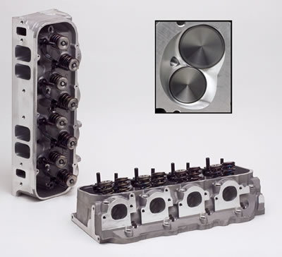
Summit Racing offers a similar Dart Pro 1 cylinder head. It is CNC-machined and has the same 121cc combustion chambers and 1.625 inch valve springs, but has larger 335cc intake ports, 138cc exhaust ports, and 2.300 inch intake valves instead of 2.250 inch valves.
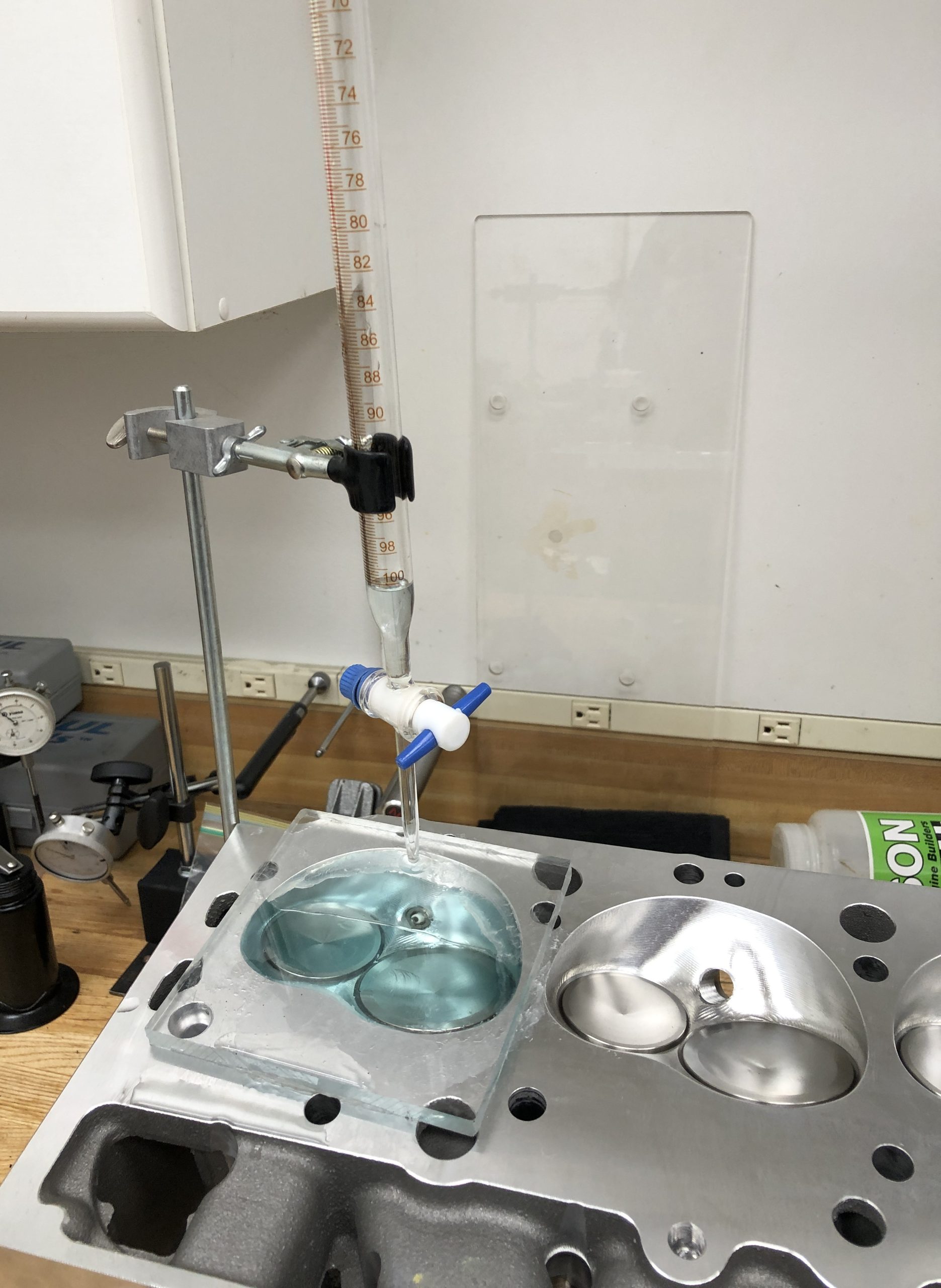
I measured combustion chamber volume for each cylinder just to be sure. Each chamber checked out at 121cc as advertised—yet another testament to Dart’s attention to detail. Due to the open-chamber head design, our calculated compression ratio is 9.86:1. This streetable ratio will provide ample horsepower and torque on readily available 93 octane pump gas.
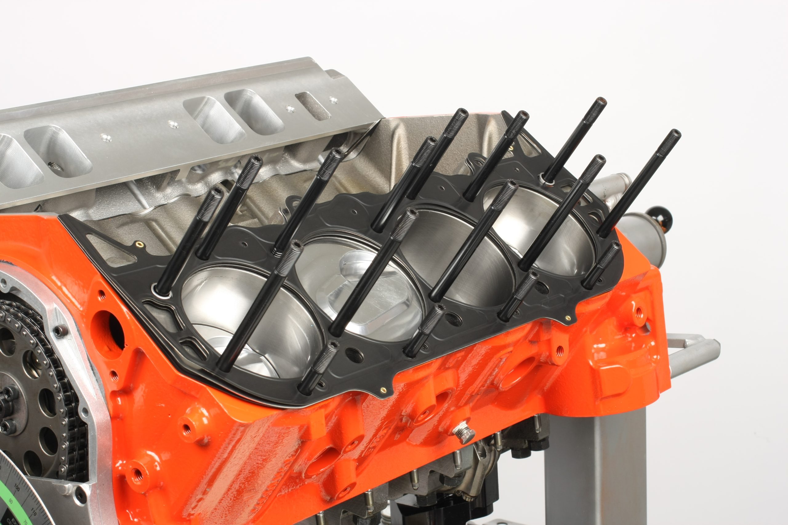
The heads were sealed to the block with Cometic MLS head gaskets and ARP head studs. The gaskets have an embossed design that promotes an even clamp load across the sealing surface to reduce bore distortion. The outer layers are coated with Viton fluoroelastomer rubber that is exceptionally heat-resistant.
The ARP head studs are designed specifically for the Pro 1 cylinder heads. This set features 12-point nuts that were torqued to 70 ft.-lbs. in three stages (30 ft.-lbs., 50 ft.-lbs., and 70 ft.-lbs.).
Checking Piston to Valve Clearance
Piston to valve clearances were checked with a dial indicator and double checked with clay. With our COMP Cams solid roller cam set straight up and a cylinder head installed with no gasket, piston to valve clearance was approximately 0.100 inch at the intake valve and 0.030 inch at the exhaust valve. Adding the 0.040 inch thick Cometic gasket increased intake clearance to 0.140 inch and exhaust to 0.070 inch.
That’s too generous at the intake valve and too tight at the exhaust. By advancing the cam by four degrees, we tightened up intake clearance to 0.120 inch and opened up the exhaust to about 0.160 inch, a good compromise.
Determining Pushrod Length
Factory big block Chevy intake pushrod length is 8.275 inches and exhaust length is 9.250 inches. Dart notes that the intake pushrod should be around 0.200 inch longer and exhaust another 0.250 inch longer, but that you must measure to make sure due to variables like deck height, head gasket thickness, and cam specs.
We started on the exhaust side with a pushrod length checker set at 9.450 inches. That made a witness mark pretty close to center on the valve tip, but just a tad toward the outside (exhaust side). Adjusting the checker to 9.400 inches provided a very satisfactory center witness mark sweep of about 0.050 inch wide on the exhaust valve tip.
The intake side proved to be stubborn. Setting the length checker to 8.450 inches netted a centered witness mark on the valve tip, but the sweep was wider than I liked at about 0.096 inch. I couldn’t improve on that, so 8.450 inch long pushrods it was.
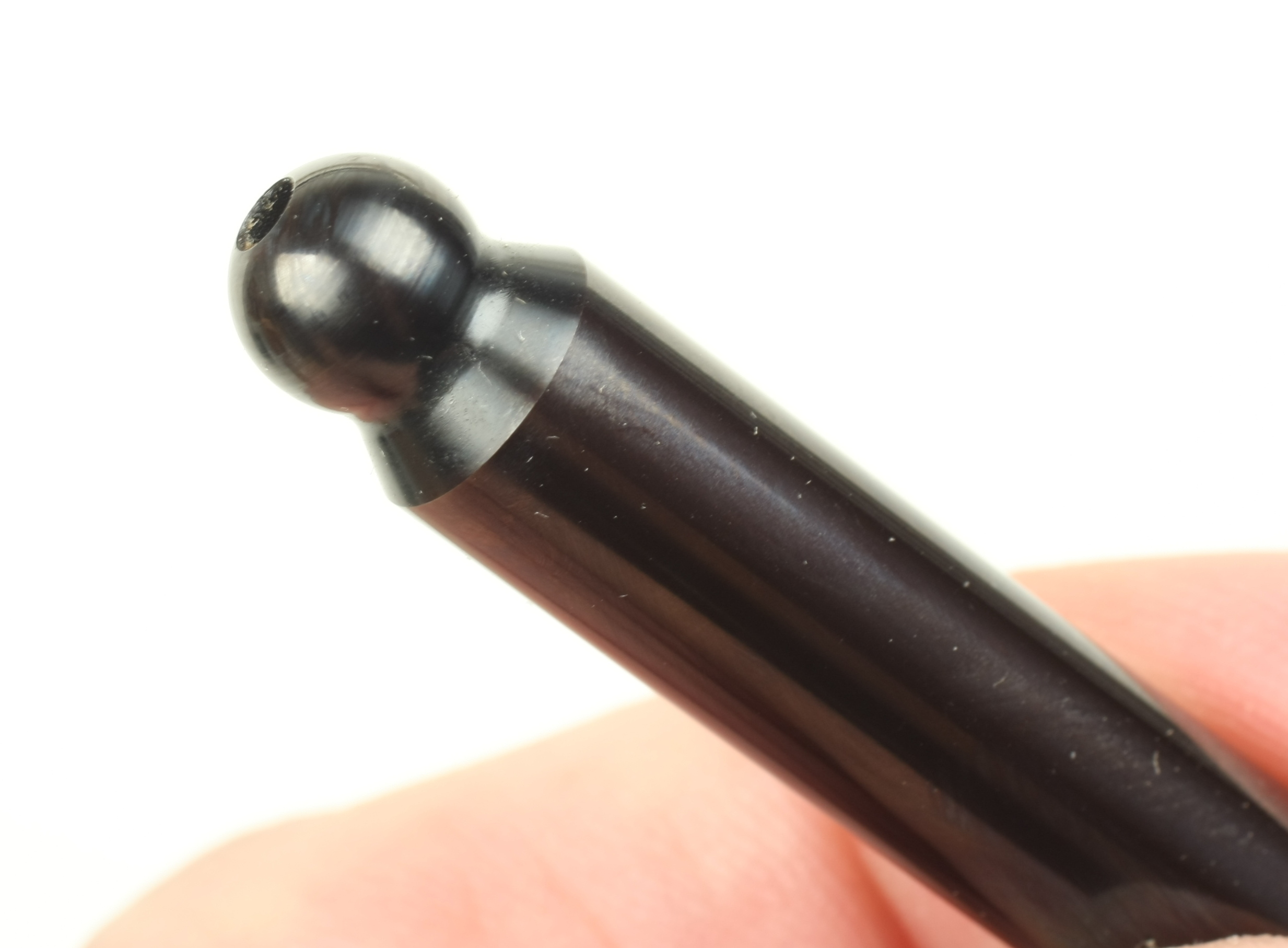
The pushrods I chose were Elgin Pro Stocks. Made from 4130 chromoly steel, the one-piece pushrods are 3/8 inch in diameter with a 0.137 inch thick wall. They also have 5/16 inch, 120 degree ball ends to accommodate high lift cams. Summit Racing carries COMP Cams Hi-Tech 210 pushrods that have very similar specifications except for slightly thinner 0.035 inch thick walls.
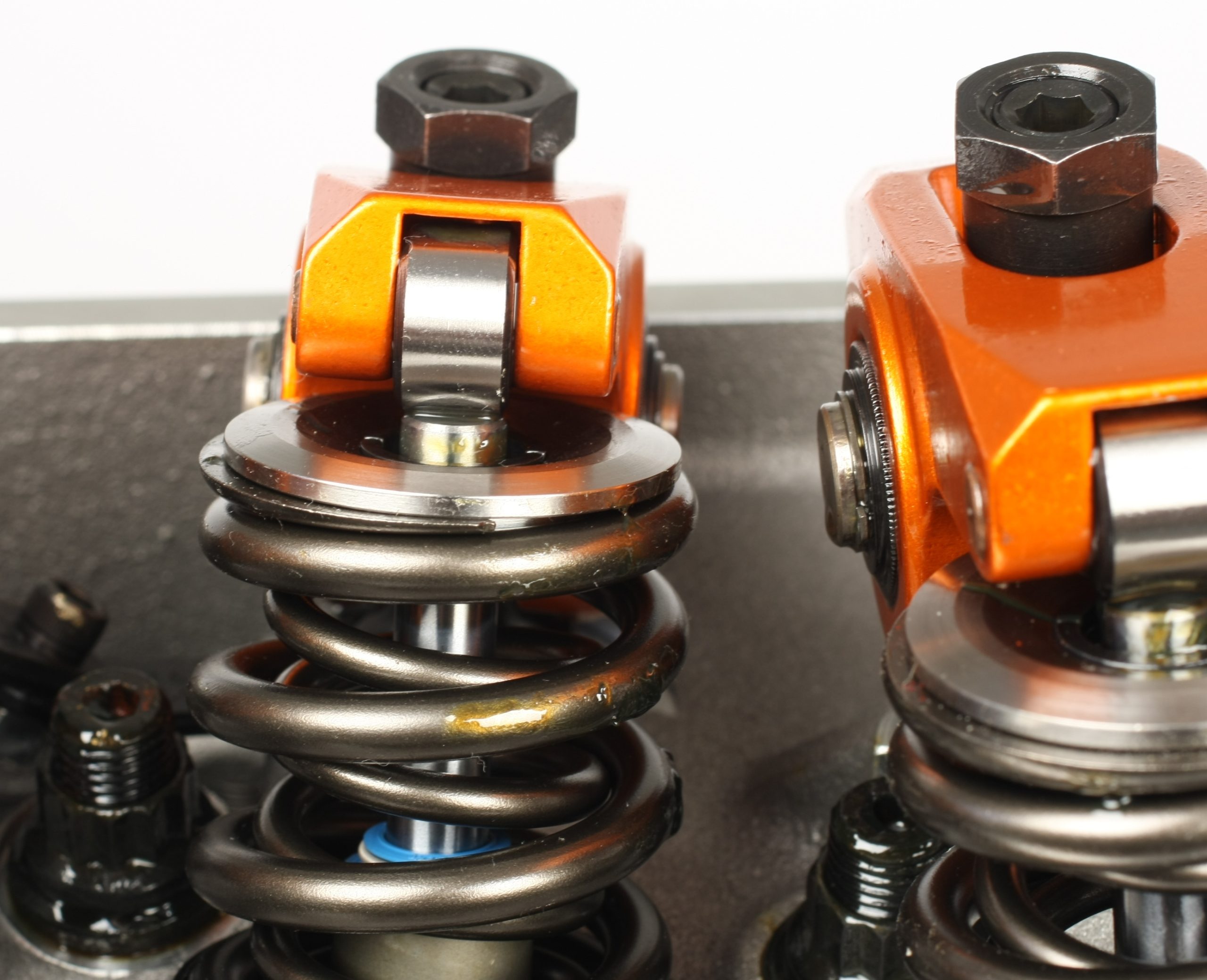
Rocker Arms
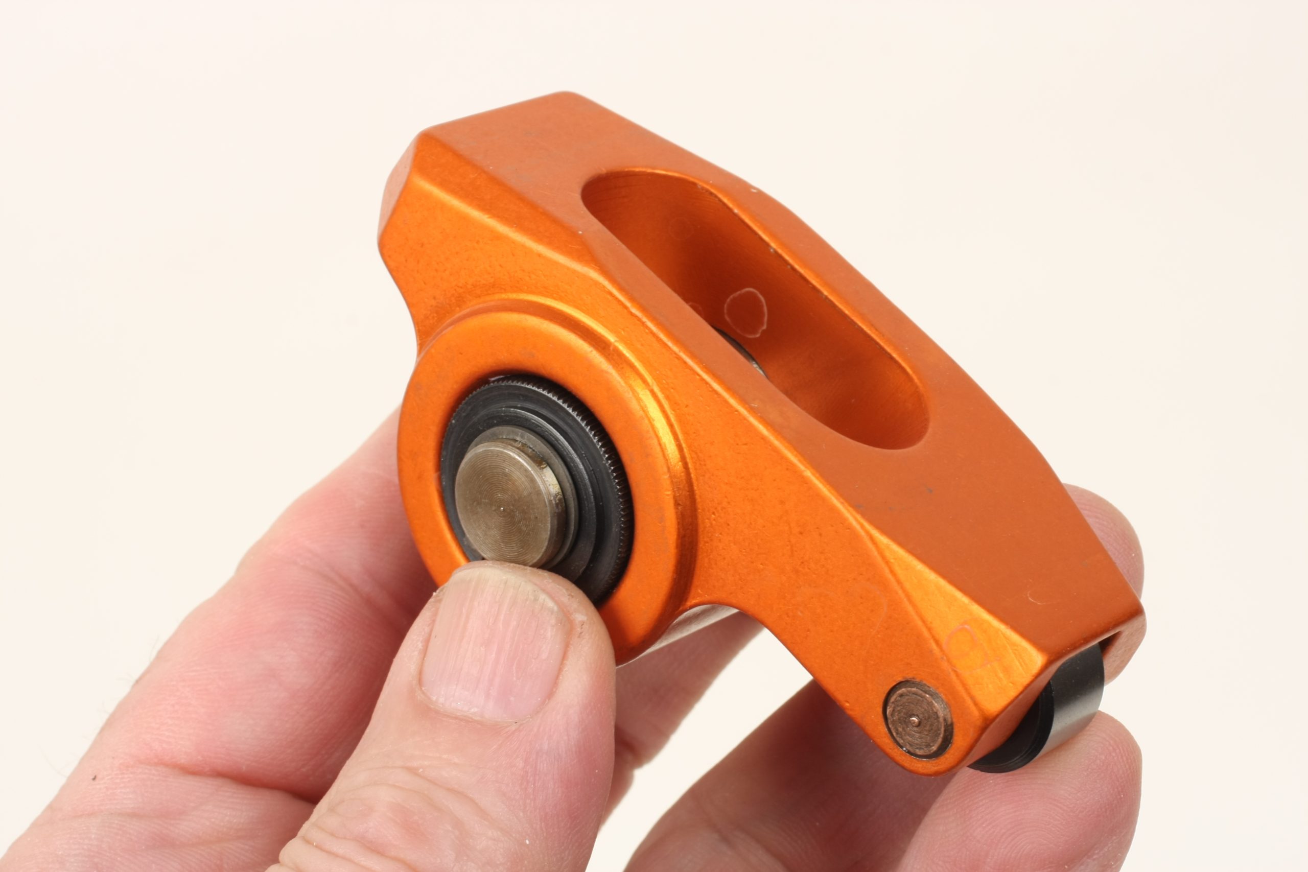
The rocker arms are Harland Sharp’s Diamond Series full rollers. The forged aluminum rockers have a 1.7 ratio, clear 1.650 inch diameter valve springs, and eliminate as much as 100 grams from the valvetrain without sacrificing strength. The low-profile rockers fit under stock-height valve covers.
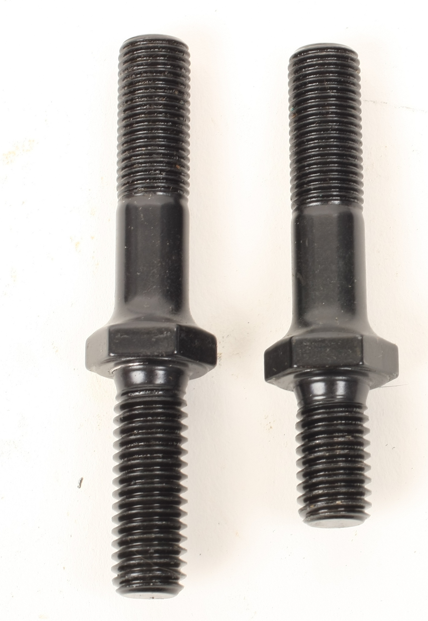
The Dart Pro 1 cylinder heads come with rocker arm studs with two different lower thread lengths. The 0.800 inch long studs are for the intake locations and the 1.300 inch long studs are for the exhaust. The exhaust rocker stud holes are blind, but the intake holes are open to intake port vacuum and require thread sealant on the studs’ lower threads. Pay attention and don’t mix them up!
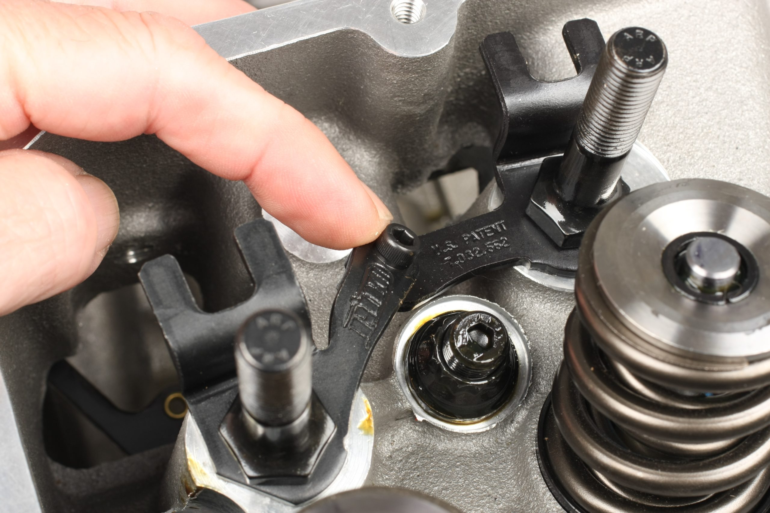
The Harland Sharp rockers use pushrod guide plates. The Dart Pro 1 heads include two-piece guide plates that are hinged at the center. When bolting the halves together the side with the Dart logo always goes on top of the other half without the logo. With the guide plates, rocker studs, pushrods, and rocker arms installed, closely examine the alignment of each rocker’s roller bearing tip to its respective valve tip.
Using a brass drift and a hammer to gently strike the fulcrum point of the guide plates, you can move and fine-tune the rocker arm rollers to properly center on the valve tips. Remove the rockers, torque the rocker studs to the final value of 55 ft.-lbs., and reinstall the rockers to verify alignment. If the rockers have moved, repeat the process.
After soaking the rockers in 30-weight oil for 30 minutes per Harland Sharp’s recommendation, a dab of assembly lube was applied to the valve tips and the rockers installed with the supplied polylocks. Cold valve lash was set at 0.020 inch.
Stud Girdles
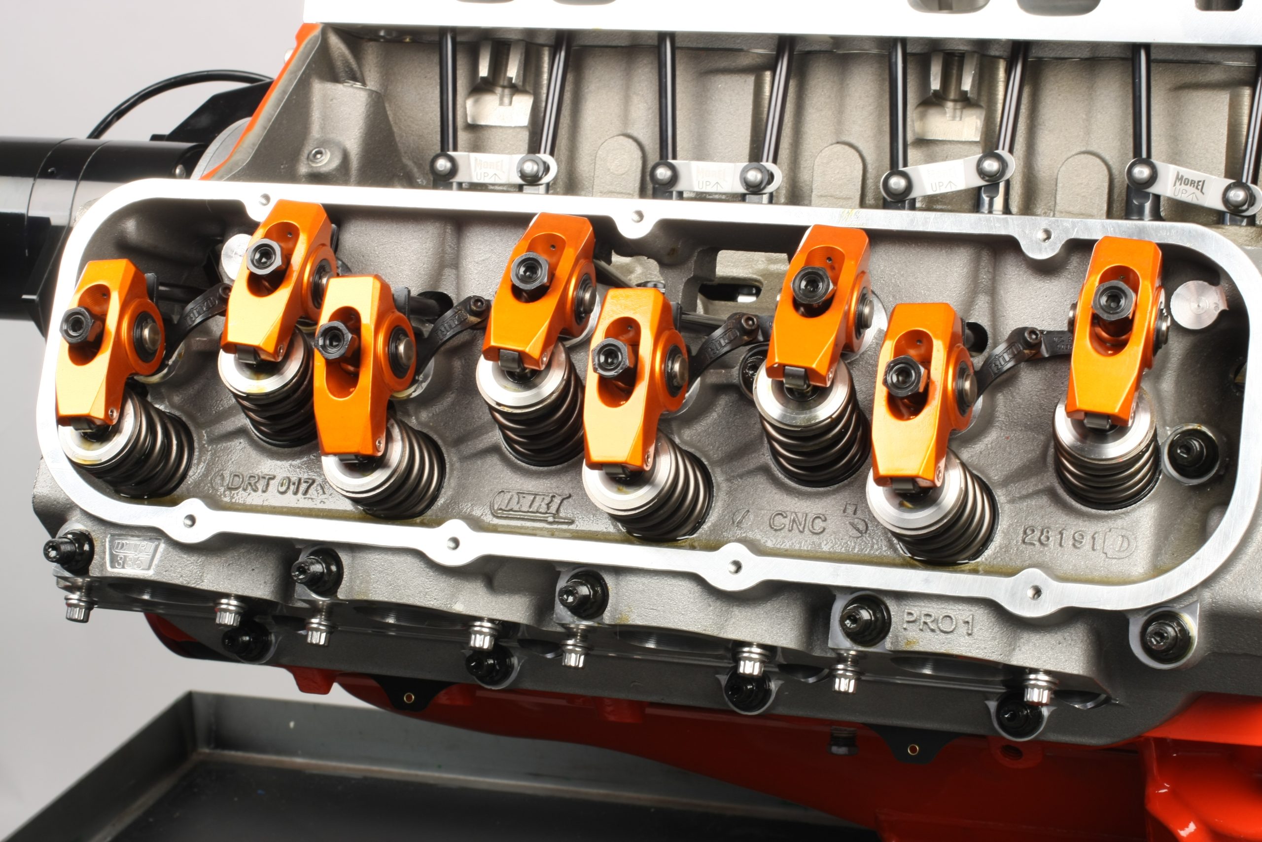
We installed a set of Dart aluminum stud girdles to tie the rocker arm studs together. This will reduce rocker stud deflection, which could have been a big issue with our stiff valve springs.
Installation is a bit tricky and definitely requires patience. First, lay the girdle assembly on the rockers with the Dart logo facing up. Loosely install the exhaust polylock nuts. Wiggle and slightly raise the girdle to get enough angle clearance to loosely install the intake polylock nuts. If you run across a polylock that won’t engage the rocker stud, wiggle/raise/lower the girdle to allow proper thread engagement. Don’t force it!
Once all polylocks are engaged, raise the girdle to a uniform height. It’s a matter of feel to obtain the desired “sweet spot” where the girdle is in its most comfortable location. Snug all polylocks until you achieve close to zero lash, then back off a few turns. Make sure that the girdle is not sitting low enough to interfere with rocker operation.
At this point, you can set valve lash, snug up the set screws, and final-tighten the girdle clamp bolts. Our COMP cam’s spec card calls for 0.020 inch hot lash. We set cold lash at 0.016 inch to compensate for component growth when the engine is at operating temperature.
Parts List
- Melling Select Billet Oil Pump
- Moroso Drag/Road Race Oil Pan
- Moroso Oil Pan Gasket
- ARP Oil Pan Studs
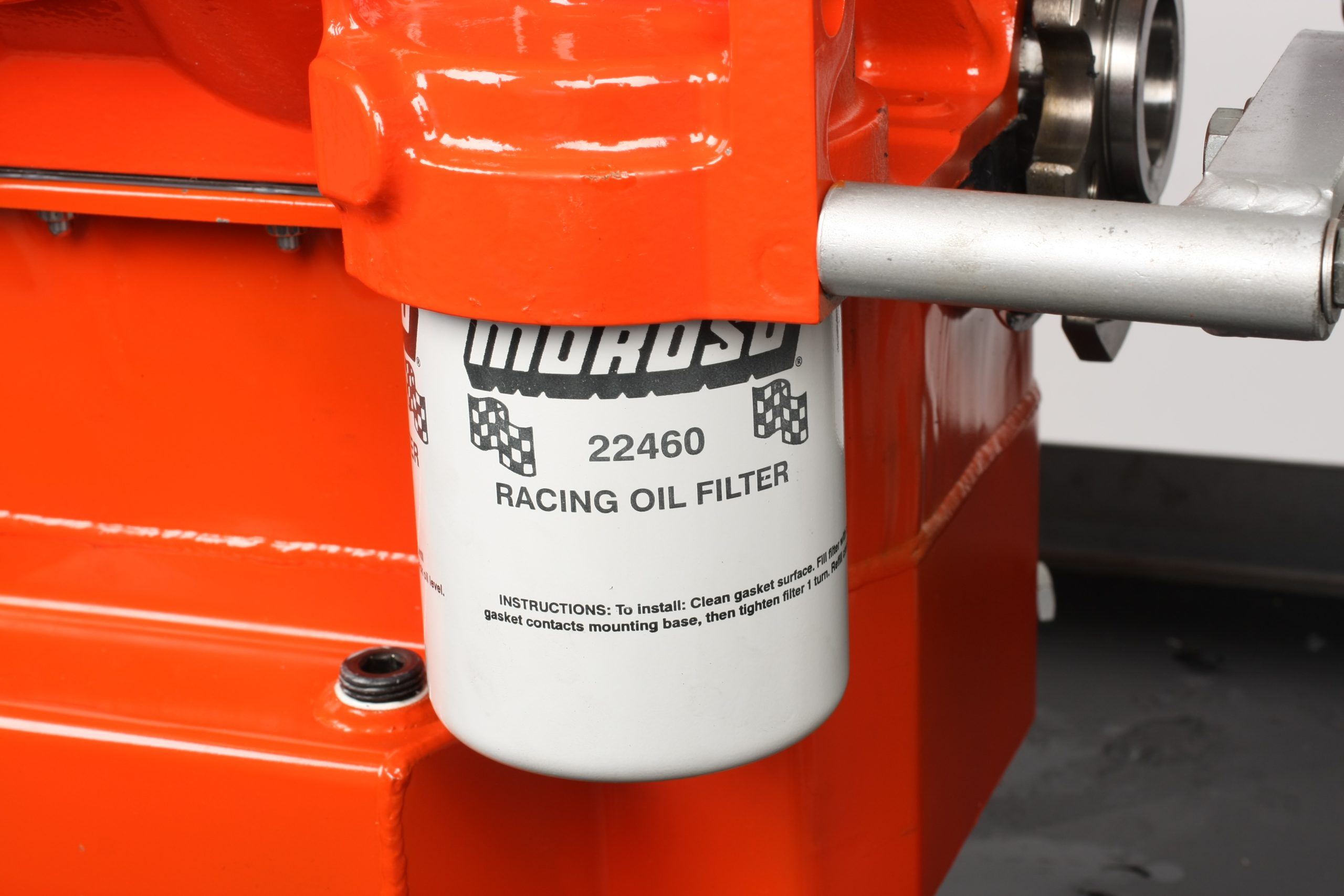
- Moroso Race Oil Filter
- Howards Cams RaceMax Solid Roller Lifters
- Dart Pro 1 Aluminum Cylinder Heads
- Harland Sharp Diamond Series Roller Rocker Arms
- Cometic MLS Cylinder Head Gaskets
- ARP Cylinder Head Studs
- Dart Aluminum Stud Girdles
- COMP Cams Hi-Tech 210 Pushrods, Intake
- COMP Cams Hi-Tech 210 Pushrods, Exhaust
- Permatex Optimum Black RTV Gasket Maker
- Royal Purple Max-Tuff Assembly Lube
Comments