Who doesn’t have a soft spot in their heart for a big-breathing Rat engine? We certainly do, which is why we’re building a 540 cubic inch big block Chevy. After all, more displacement equals more fun!
In this article, we’ll be building the short block and installing a COMP Cams roller camshaft. We’ll talk about block prep, bearing clearance, balancing the reciprocating assembly, and fitting piston rings.
If you’d like to see the other stories in this build series, check them out here:
The Block
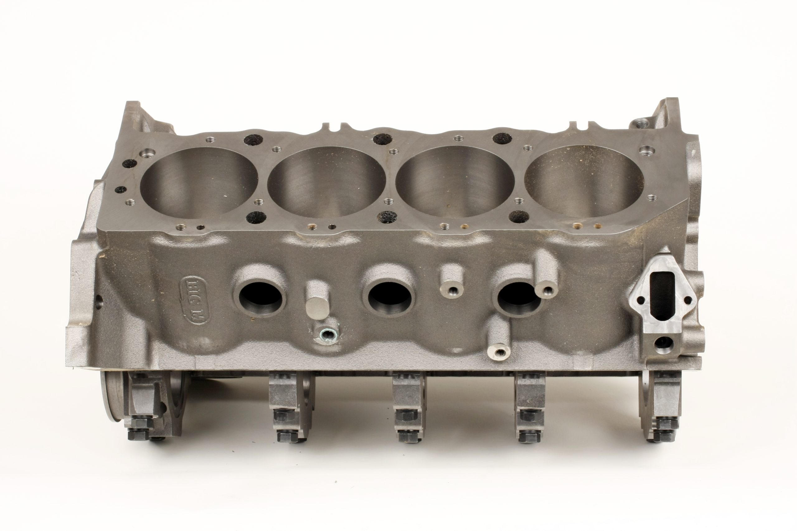
Rather than messing around with an old OEM core, we opted for a brand spanking new Dart Mark IV Big M iron block. Cast from high-nickel cast iron, the block features priority main oiling, 0.350 inch longer lifter bores for increased lifter support, and thicker decks. The 0.300 inch minimum cylinder wall thickness allows a maximum bore size of 4.625 inches. The Big M block accepts standard big block components and is drilled for a standard or stroker oil pan. We chose four-bolt billet steel main caps. Ductile iron main caps are also available.
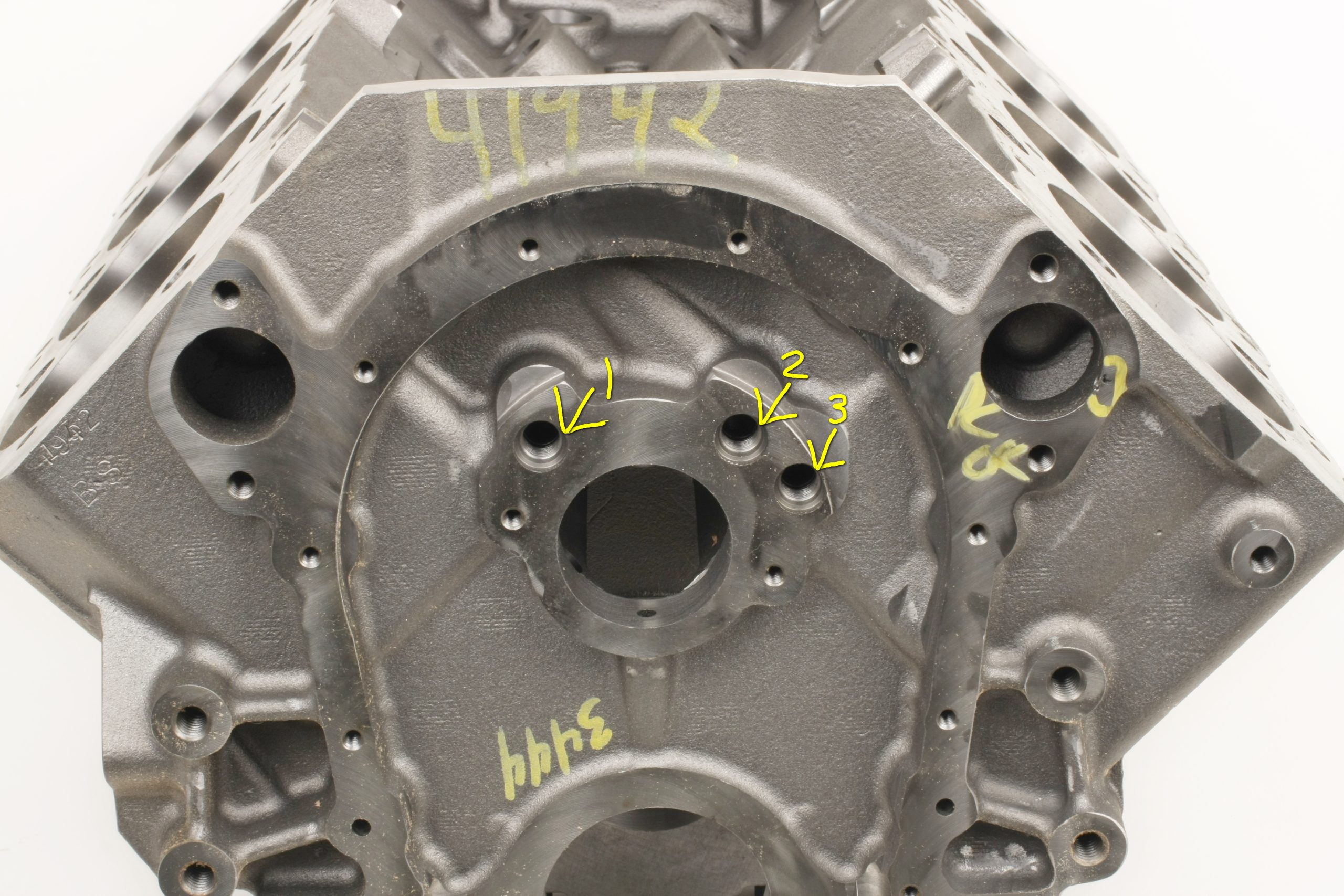
The front and rear of our block’s main oil feed and lifter galley ports feature straight AN threads, not NPT. Dart supplies the necessary plugs with the block. Dart includes the freeze plugs but not the cam bearings. Those are available in a Dart kit that comes with block dowels.
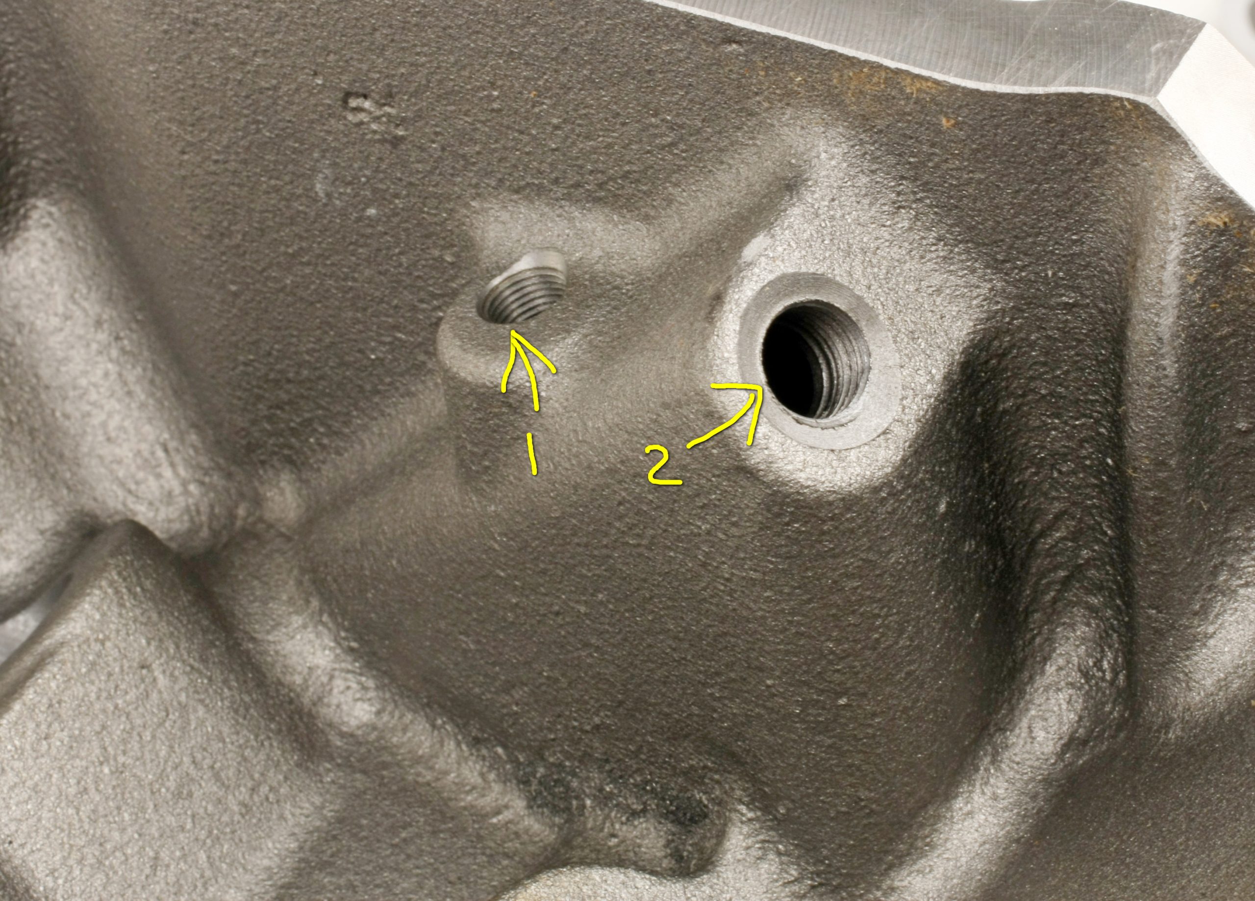
The top rear left side of the block features a 1/2 inch NPT port (to be used if running a remote oil filter) and a 1/4 inch NPT port for an oil pressure gauge.
Block Prep
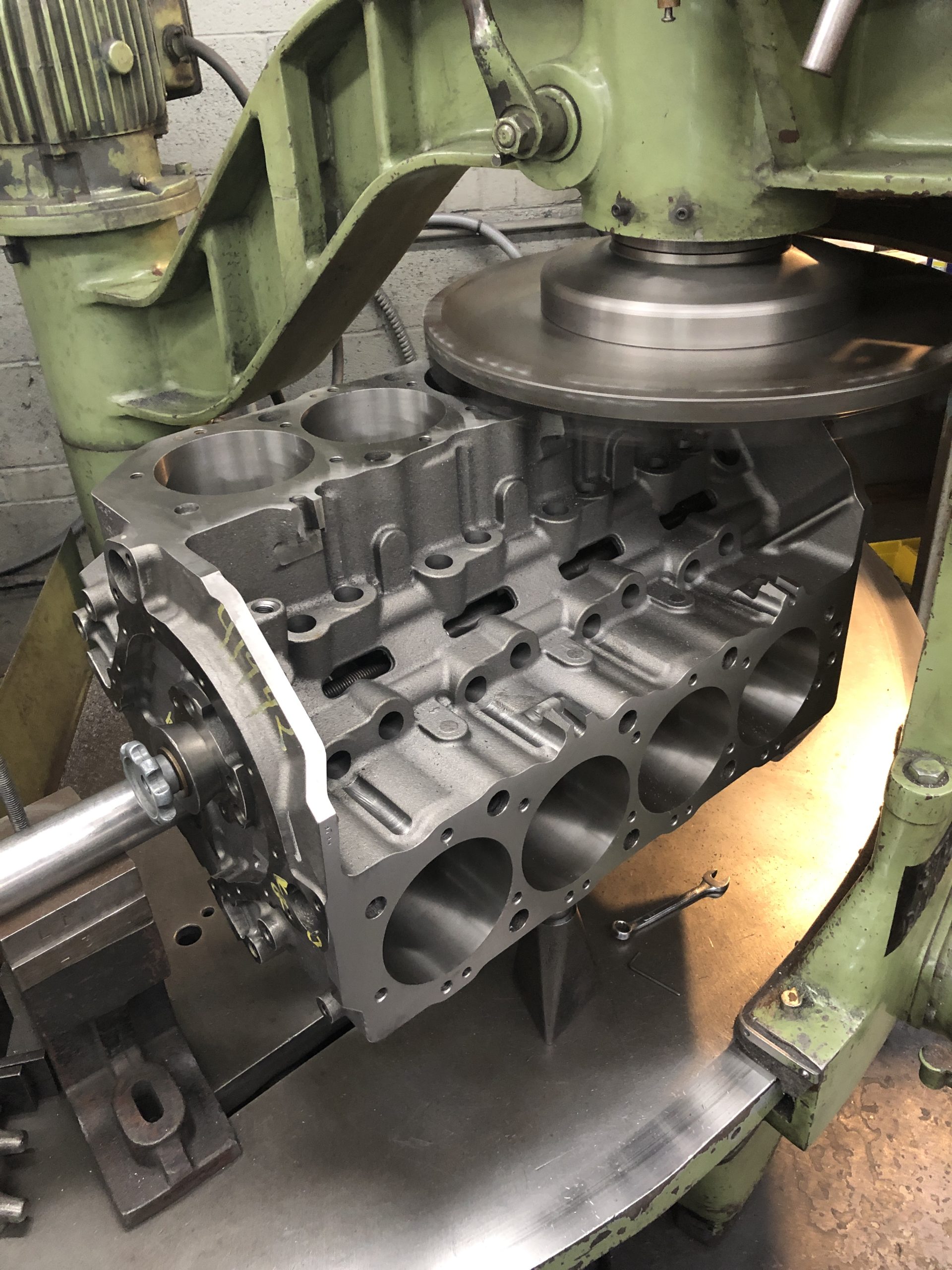
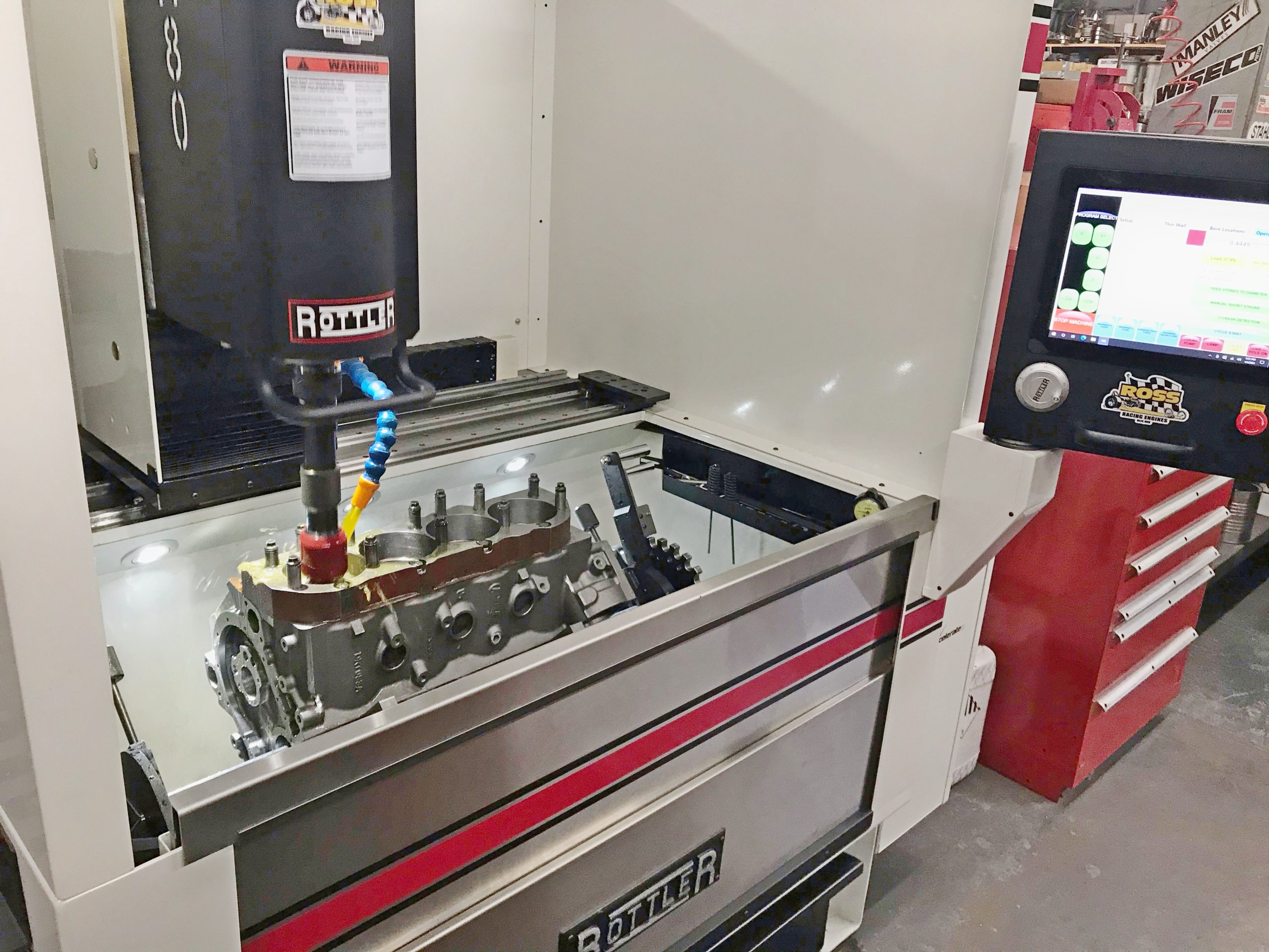
I began block prep by grinding off minor casting flashings in the lifter valley drain holes and removing sharp edges from the cam bore entries and freeze plug holes. Tony Lombardi of Ross Racing Engines in Niles, Ohio decked the block to a height of 9.7940 inches, which left our pistons 0.014 inch below deck at Top Dead Center (TDC). We could have gone with tighter piston-to-deck clearance, but our final deck height provides a bit of extra valve clearance for a “just in case” scenario.
The cylinders were bored to 4.497 inches in diameter, then CNC-honed to a final diameter of 4.500 inches with deck plates in place. Piston-to-wall clearance was 0.0045 inch. Tony removed 0.0005 inch of material from the lifter bores to obtain 0.0017 inch of oil clearance for our solid roller lifters.
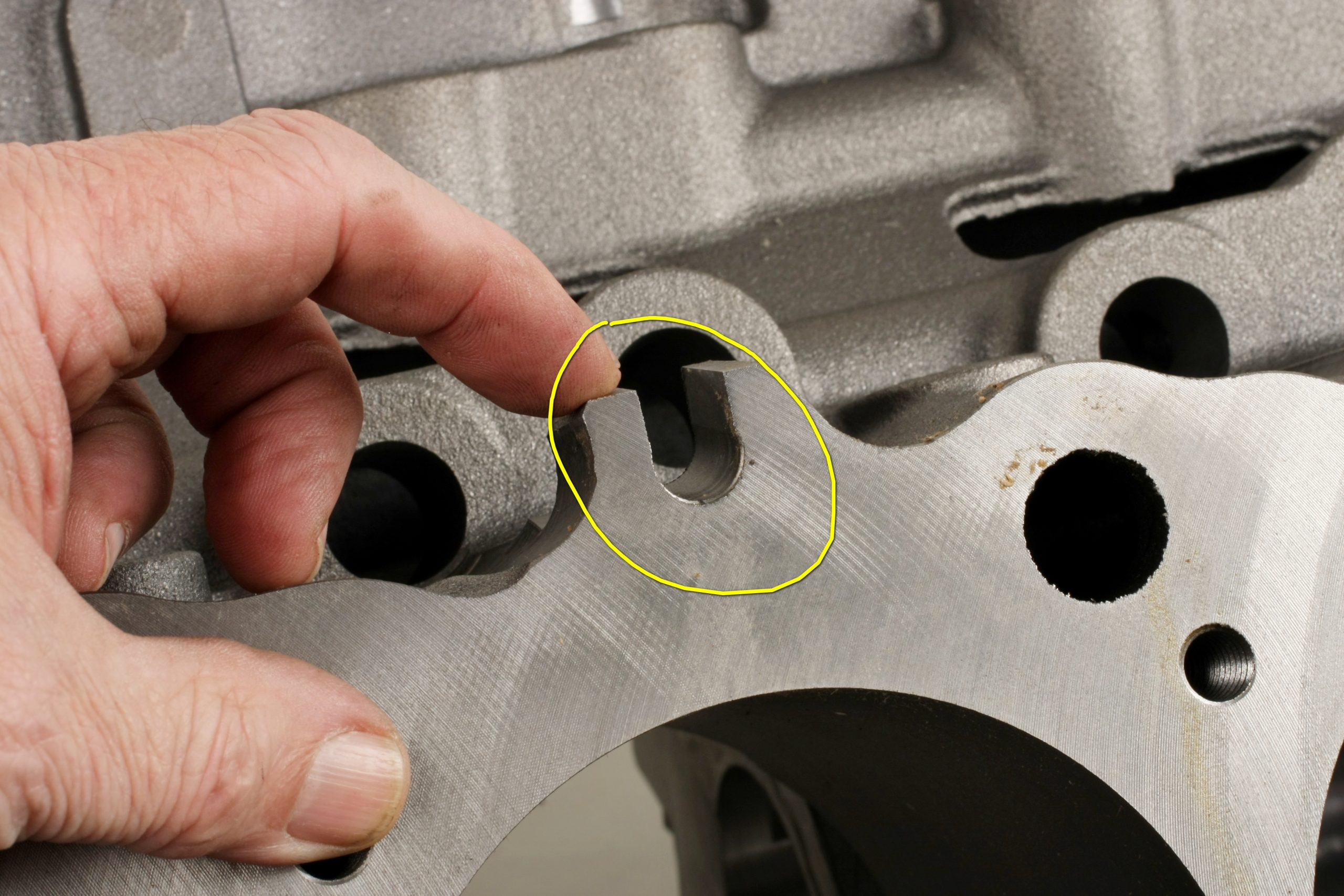
Dart notched the Big M block for rod bolt clearance when using a stroker crankshaft. Being the careful type, we checked anyway. We installed the crankshaft and piston/rod assemblies in the block, then carefully rotated the crank to check for rod big end-to-block clearance. It came in at 0.285 to 0.300 inch, providing more than enough room.
Crank counterweight to piston pin boss clearance was also checked. The tightest clearance was 0.100 inch, again more than adequate as I consider 0.060 inch as a minimum.
After machining, the Dart block went to Jodi Holtrey of Medina Mountain Motor in Creston, Ohio for a thorough power wash. When I got the block home I cleaned it again using extremely hot water and Dawn dishwashing liquid. I scrubbed all of the holes and passages using an assortment of bore brushes, rinsed off the block, and dried it with compressed air. The bores and decks were lightly coated with WD40. The block was then masked and painted using SEM self-etching primer, gray primer, and three coats of old-school Chevy Orange.
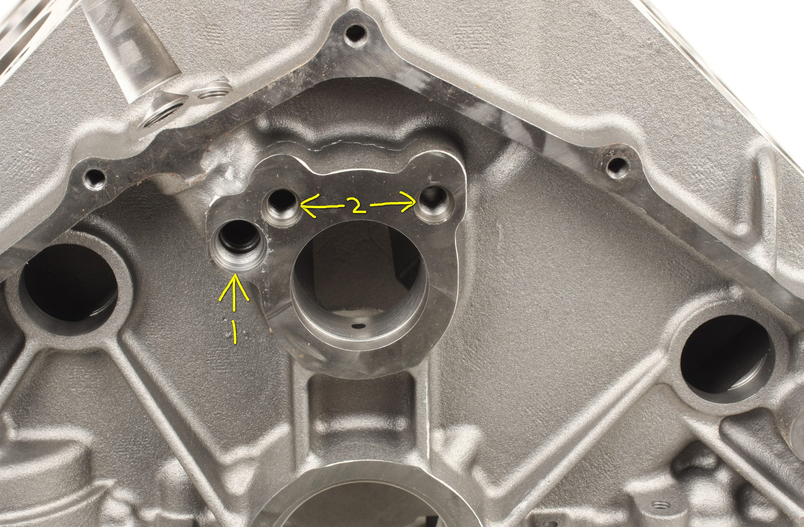
The forward end of the lifter valley features two NPT threaded holes that intersect the lifter galleys. There is a 1/8 inch NPT oil restrictor hole under the larger 1/4 inch NPT plug. Since we’re running a solid roller cam, we opted not to install a restrictor plug.
Crankshaft, Connecting Rods & Pistons
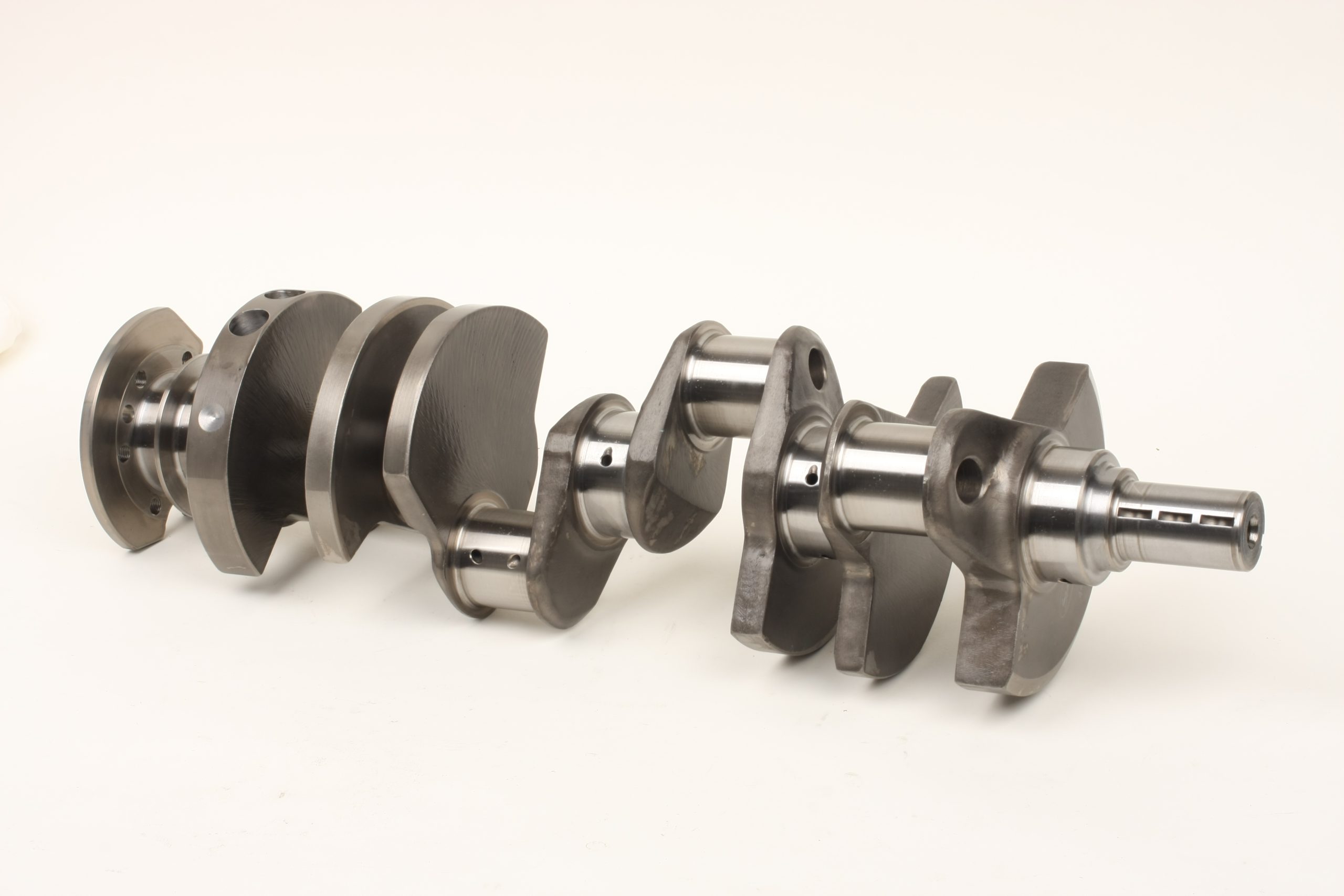
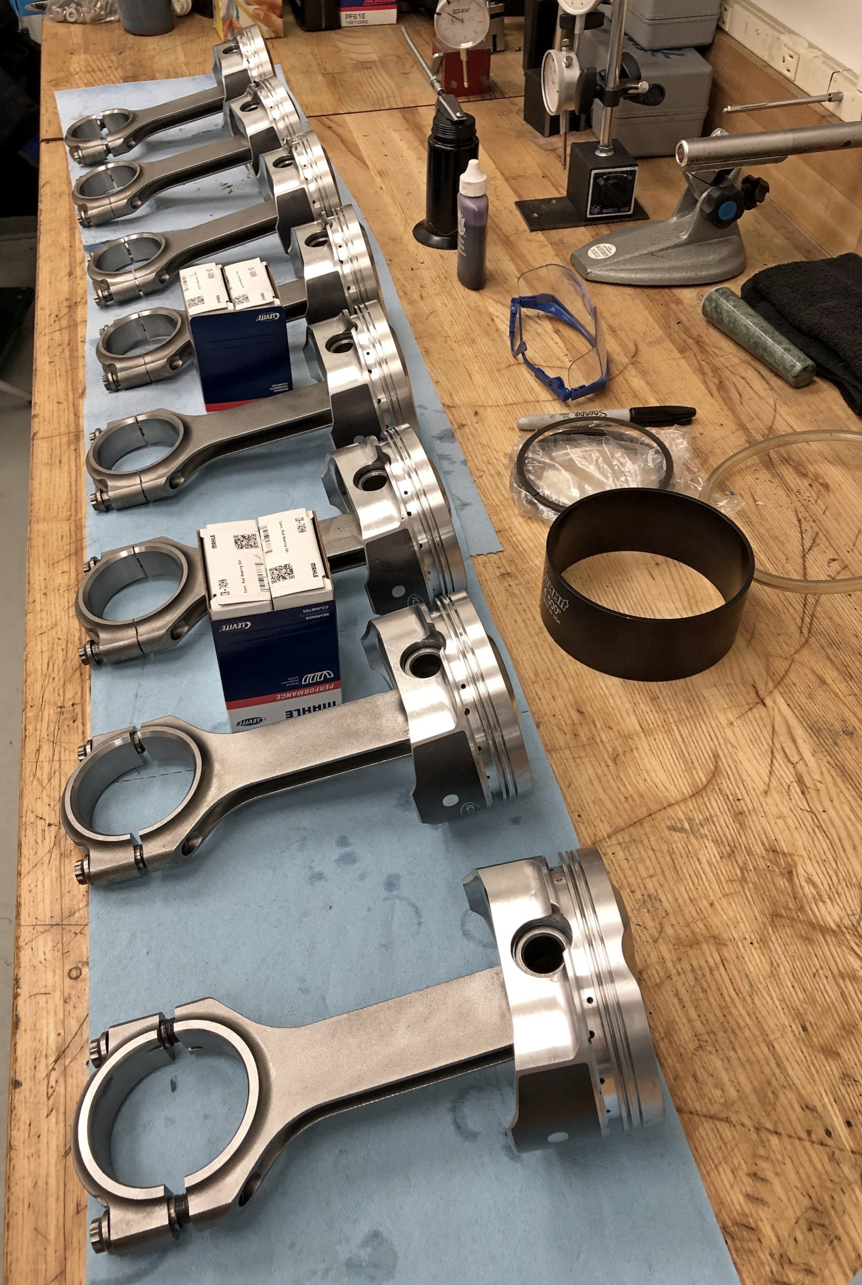
Our Scat forged stroker crankshaft features a 4.250 inch stroke, 2.200 inch rod journals, and 2.749 inch main journals. All fillets were precision-radiused, and all oil holes have smooth chamfers and lead-in paths. The crank requires narrow rod bearings to clear the generous rod journal fillets. Scat really did a nice job on this piece.
Our Scat H-beam forged steel rods have a center-to-center length of 6.385 inches. The floating pin diameter is 0.9900 inch. The rods were fitted with Clevite H-Series standard bearings in the rod caps and 0.001 inch thinner bearings in the rod big ends. Oil clearance checked in at 0.0025 inch, which is perfectly acceptable.
Just an FYI: Take the time to read the instructions supplied with aftermarket rods. Torque recommendations and maximum rod bolt stretch specs will differ depending on the size and type of rod bolts.
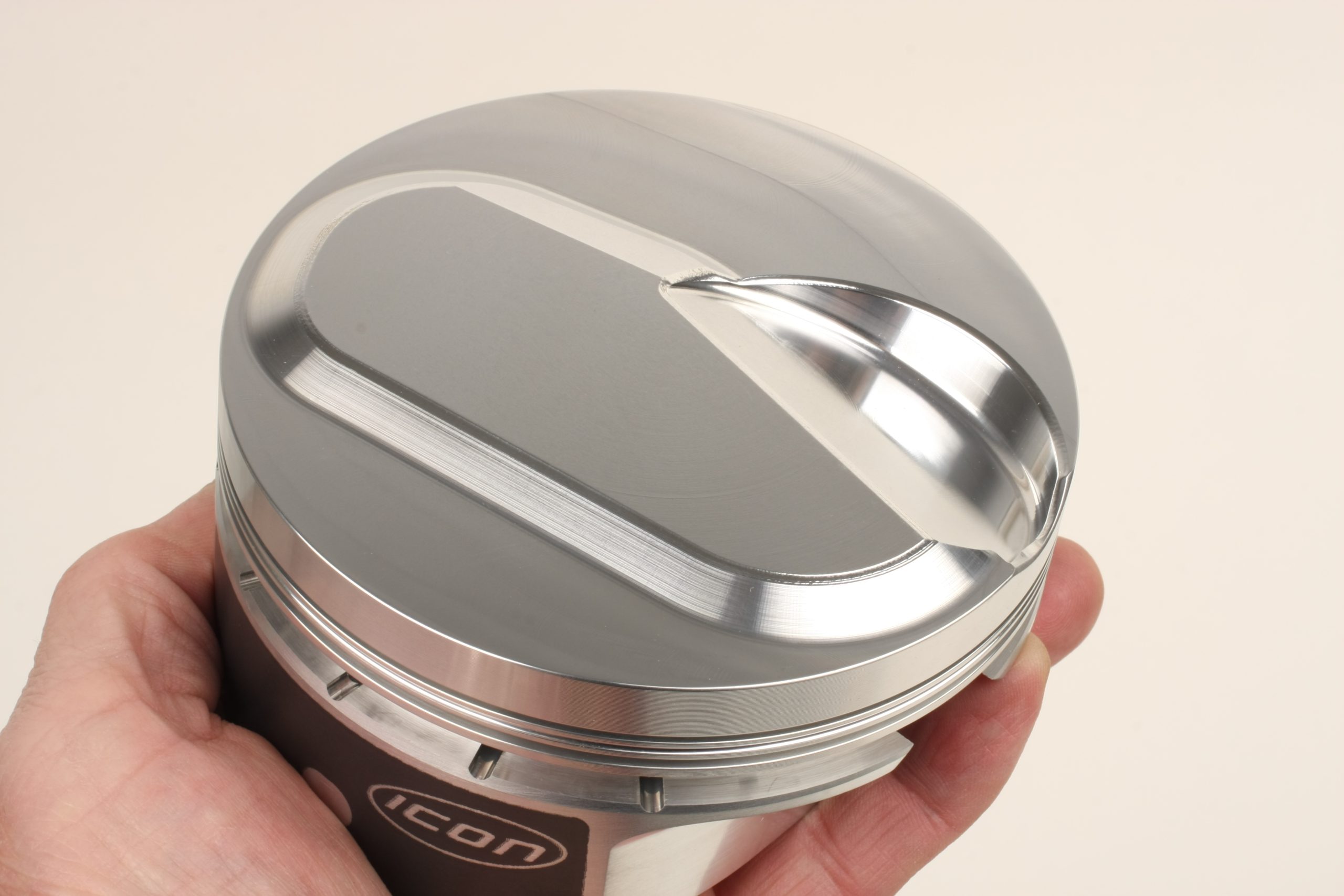
The pistons are ICON forged aluminum with 10cc domes. They feature CNC-machined crown and valve reliefs, diamond-machined skirts with an anti-friction coating, gas accumulator ring grooves, and pressure-drilled pin hole oiling. They come with full-floating 0.990 inch Trend wrist pins secured with a single spiral lock.
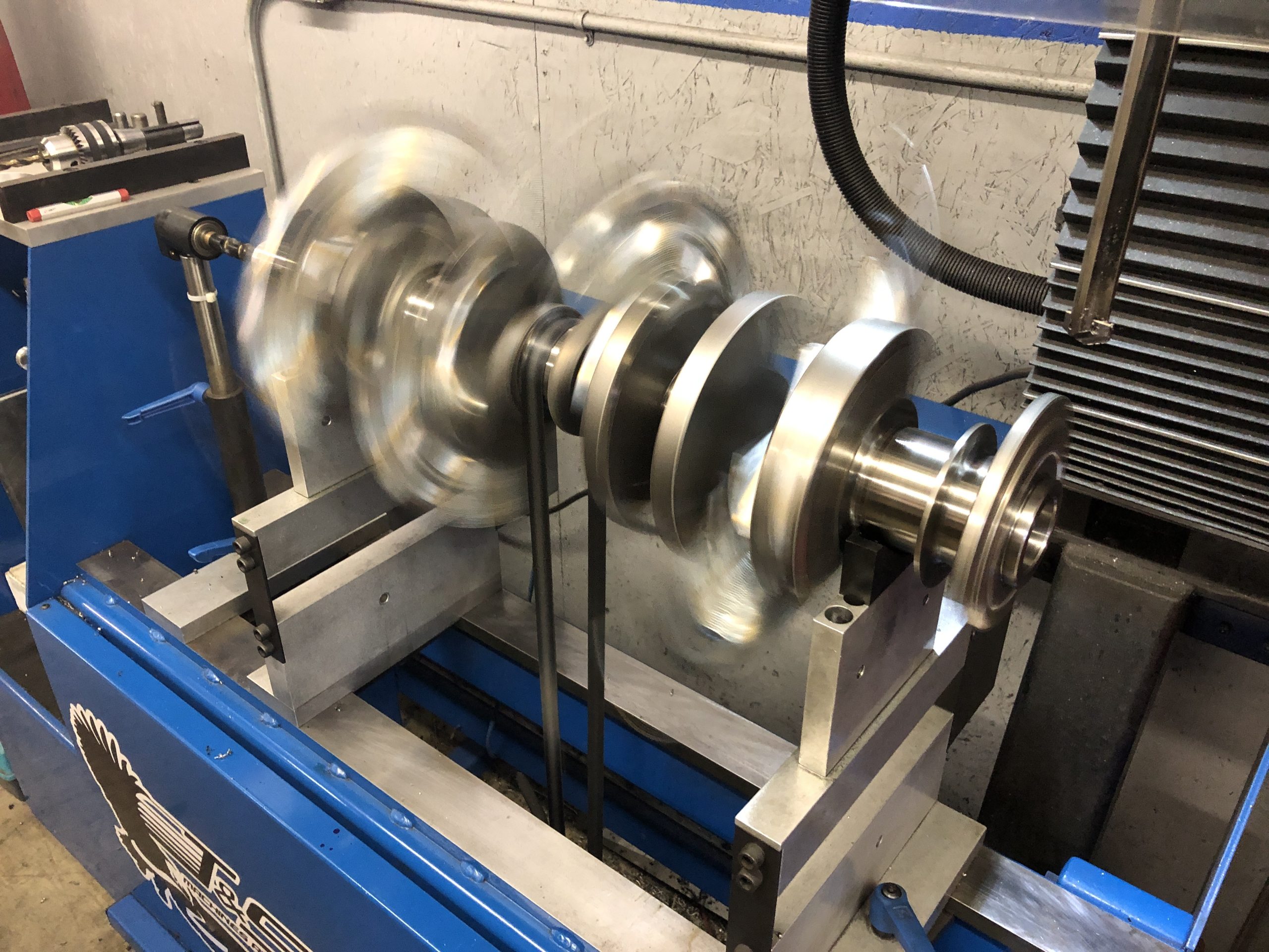
Reciprocating Assembly Balancing
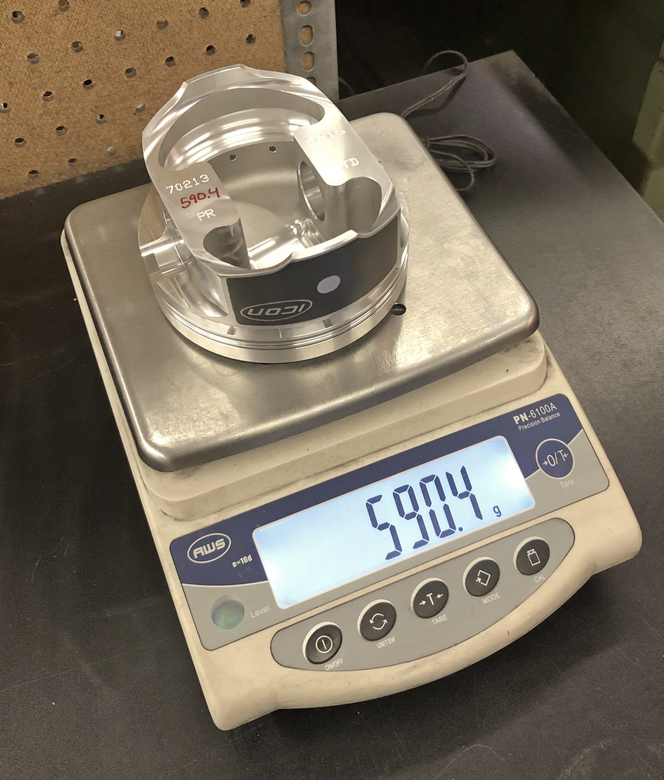
Balancing was performed by Craig Haslem at RPM Engine & Machine in Medina, Ohio. All reciprocating assembly components were weighed individually as follows. Each bobweight came out at 2,269.40 grams:
- Rod total weight: 797 grams
- Rod big end: 550.40 grams
- Rod small end: 246.60 grams
- Rod bearing: 48.30 grams
- Piston: 590.40 grams
- Piston pin: 175.10 grams
- Pin locks: 4.40 grams
- Piston rings: 37.70 grams
- Oil ring support rail: 9.80 grams
- Oil: 8.00 grams
Balance correction was a relatively easy task—only a small amount of weight had to be removed from the front and rear crankshaft counterweights. No heavy metal was required.
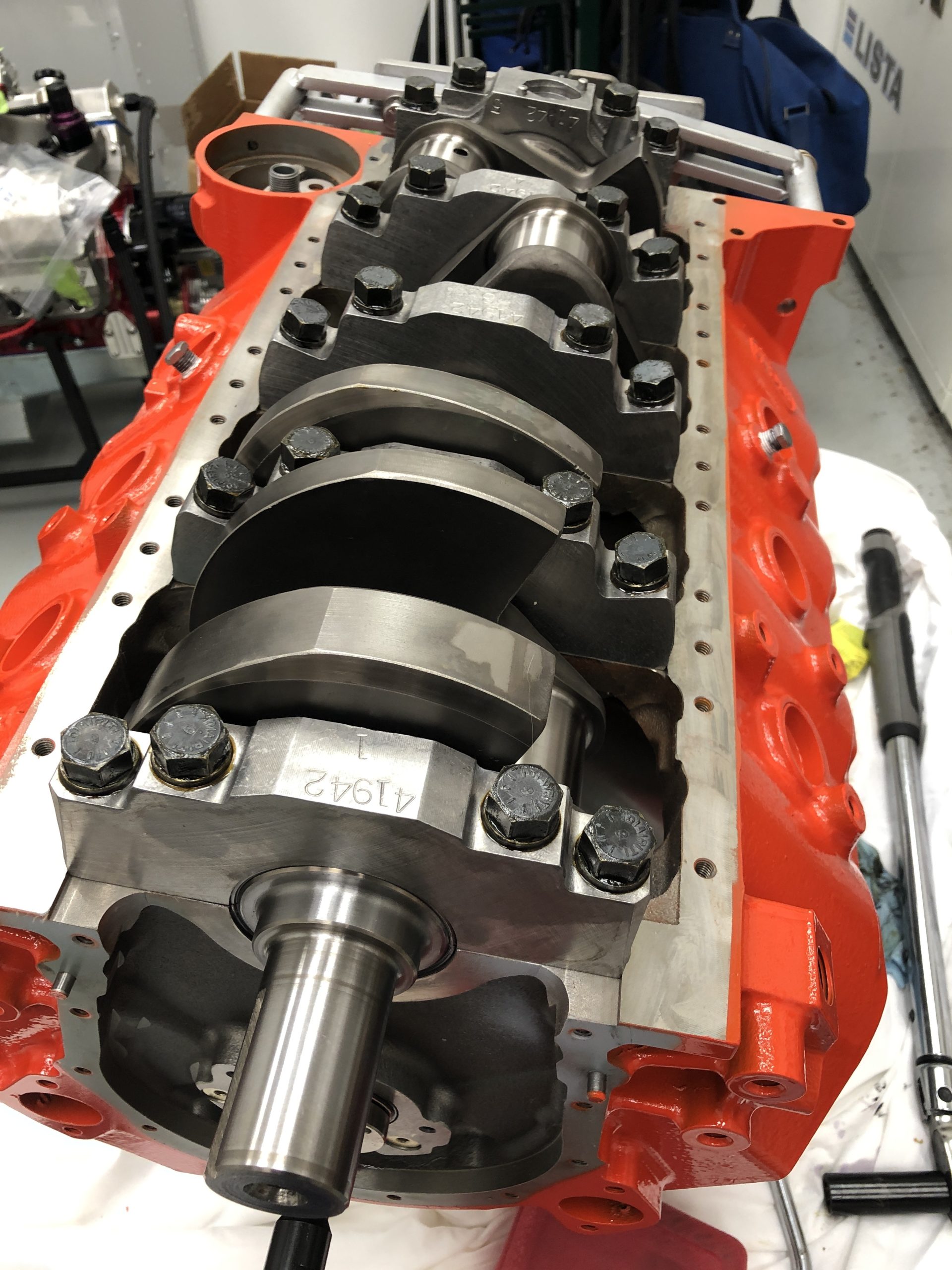
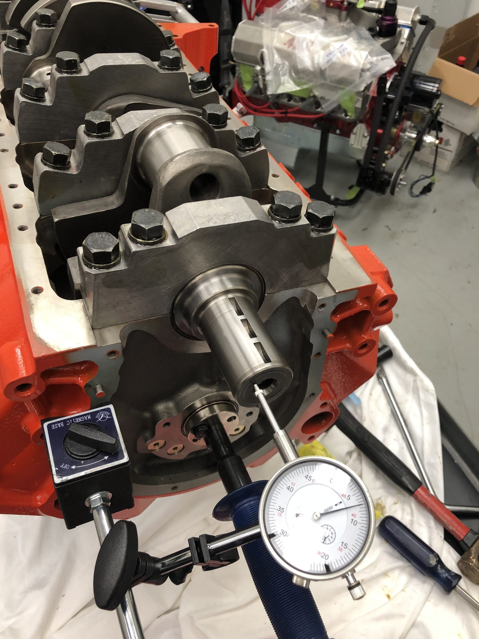
Main Bearing Clearance
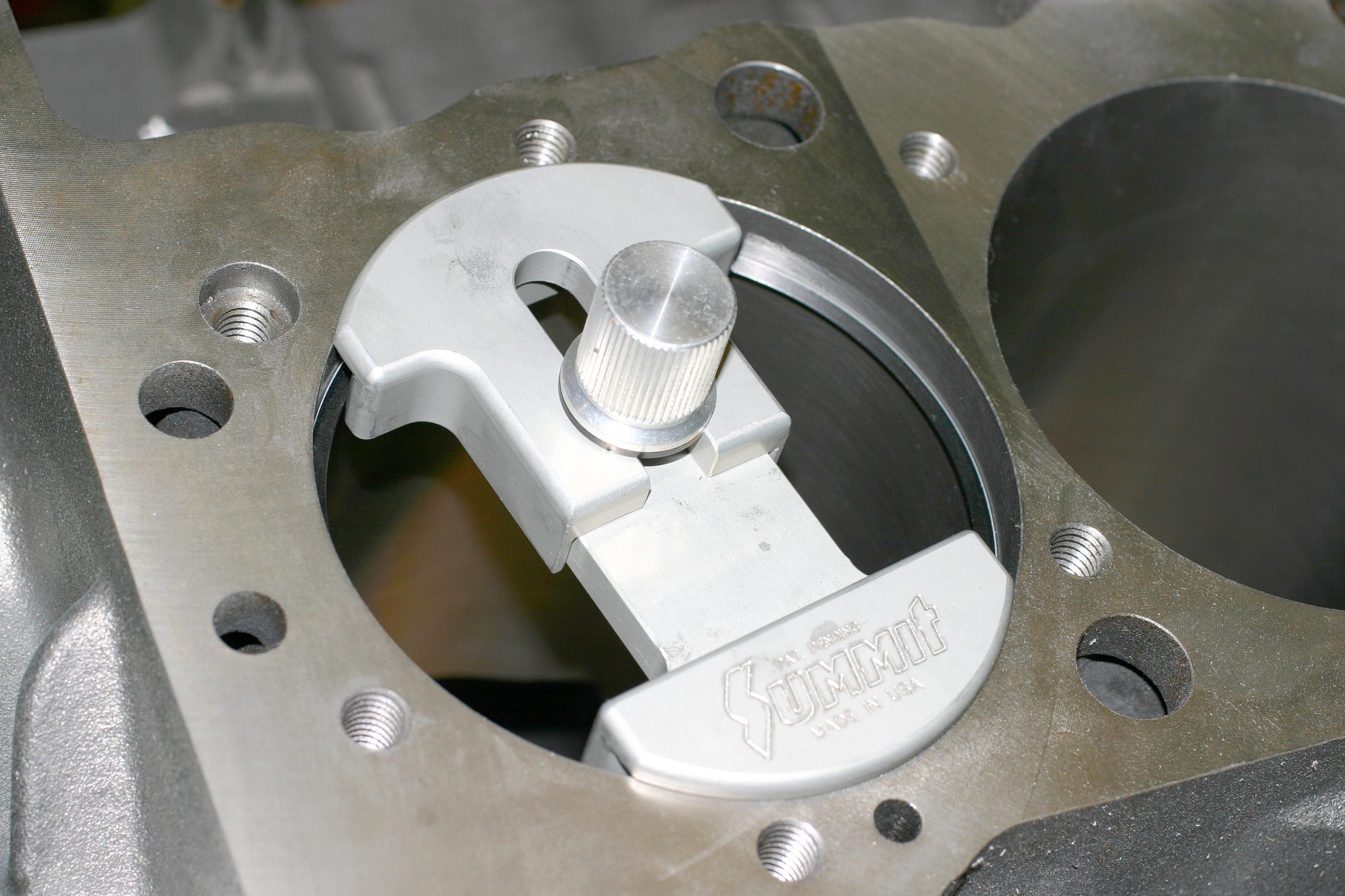
With main bearings and main caps installed, I checked main bearing oil clearance with a bore gauge. Clearance at each bearing was 0.003 inch. 0.0025 to 0.003 inch is an acceptable standard for a big block Chevy.
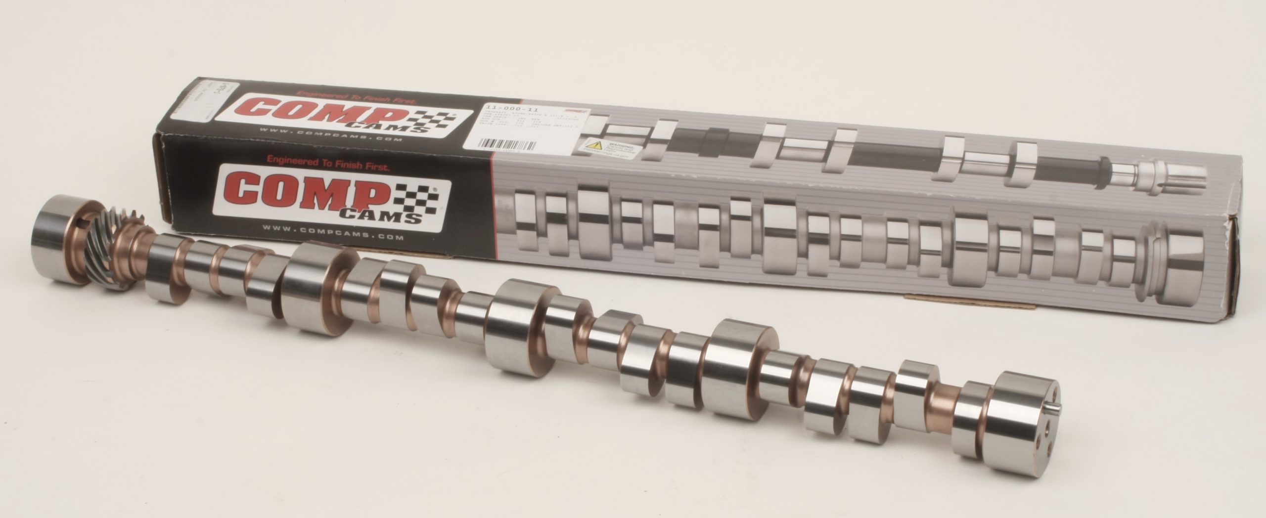
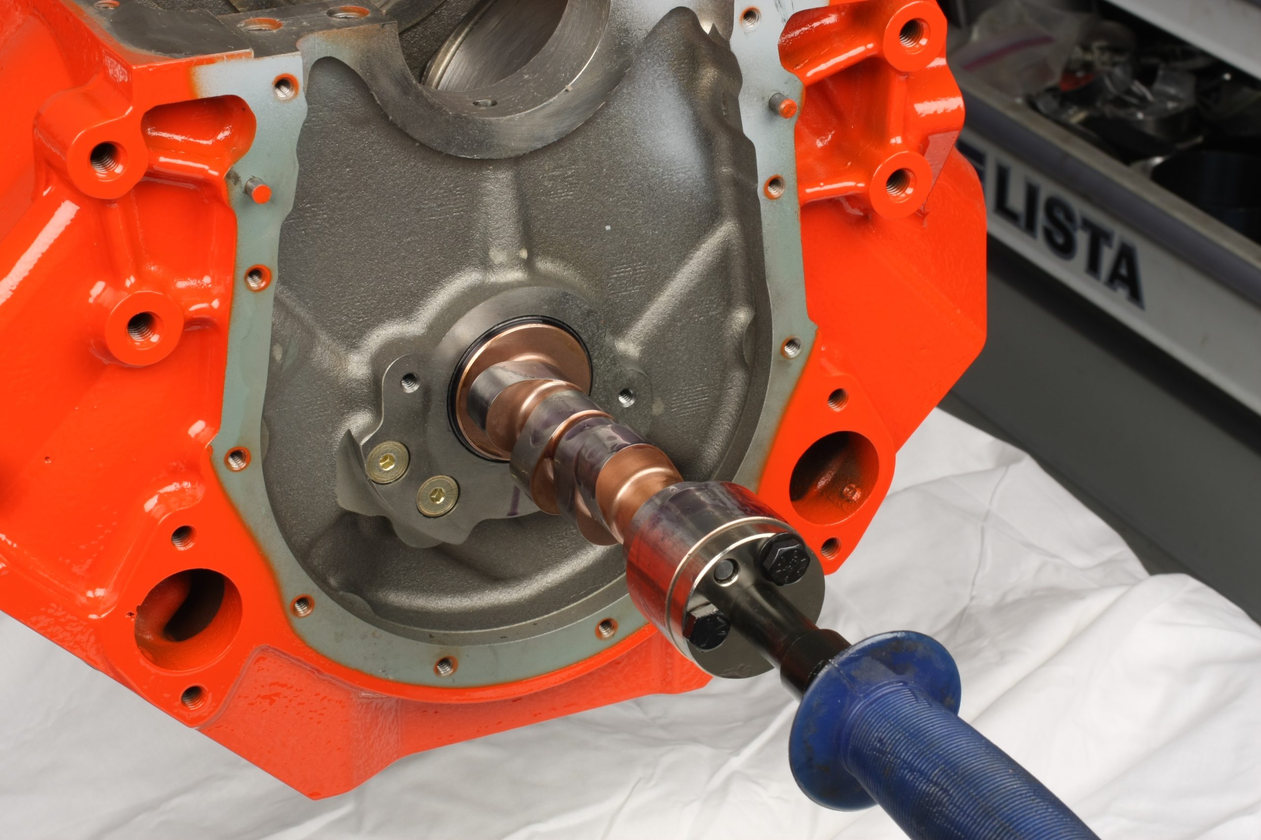
Camshaft Installation
We speced a COMP Cams billet steel solid roller camshaft for this build:
- Advertised Duration: 312°/318°
- Duration @ .050: 276°/282°
- Valve Lift with 1.7:1 Rocker Arms: 0.715″/0.715″
- Lobe Separation Angle: 111°
The camshaft has a 4/7 swap firing order (1-8-7-3-6-5-4-2). Changing the firing order for a 90 degree V8 offers several benefits. It helps improve engine cooling by moving the hot spot from the back of the engine (5/7 cylinder pair) to the 4/2 cylinder pair that are closer to the water pump. Moving the adjacent-firing cylinders forward also helps keep the combustion chambers cooler, allowing you to run slightly more timing without detonation. The swap can help stabilize the valvetrain and reduce stress and torsional vibration on the crankshaft and main bearings. That improves engine life and smoothness.
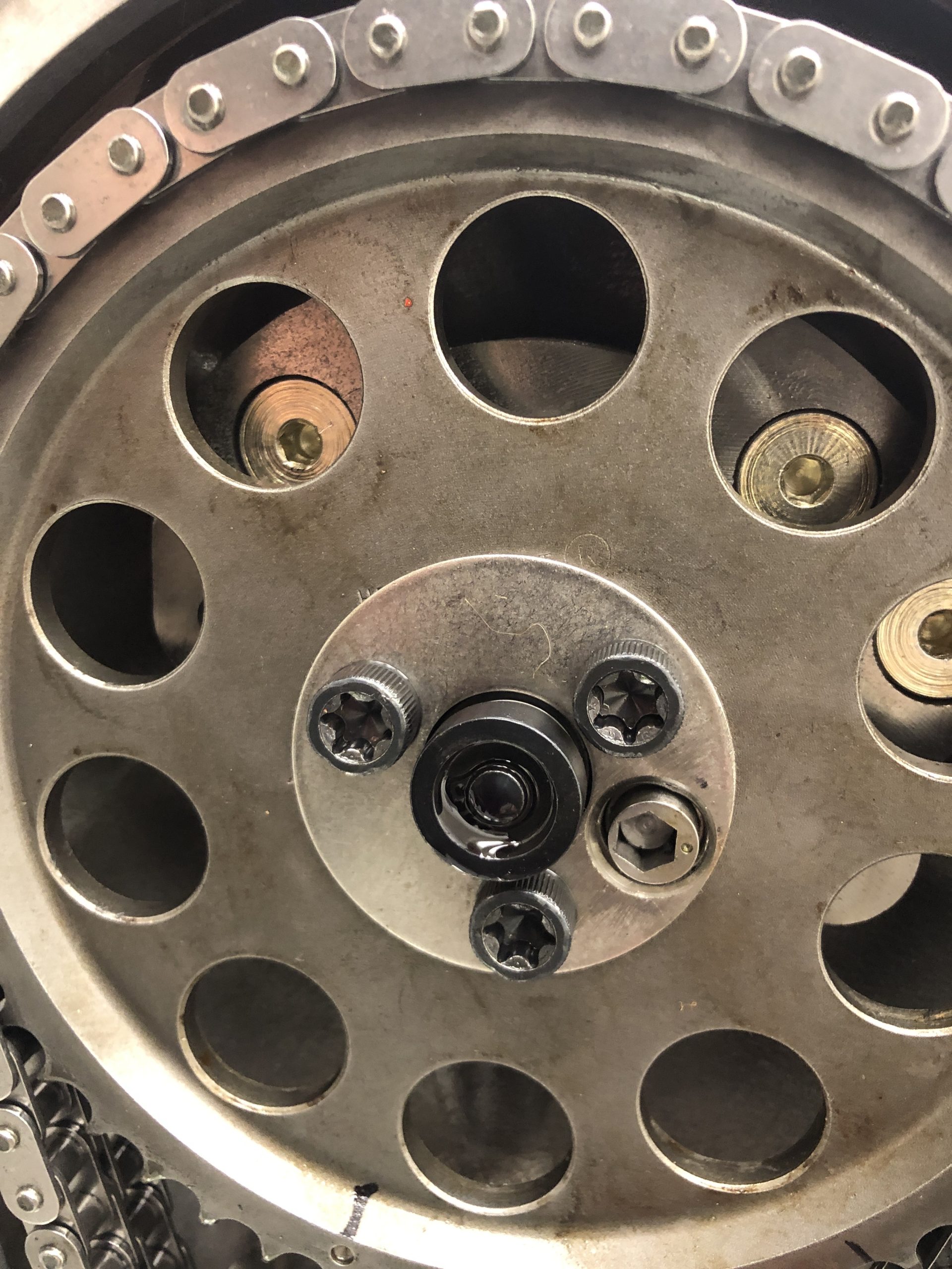
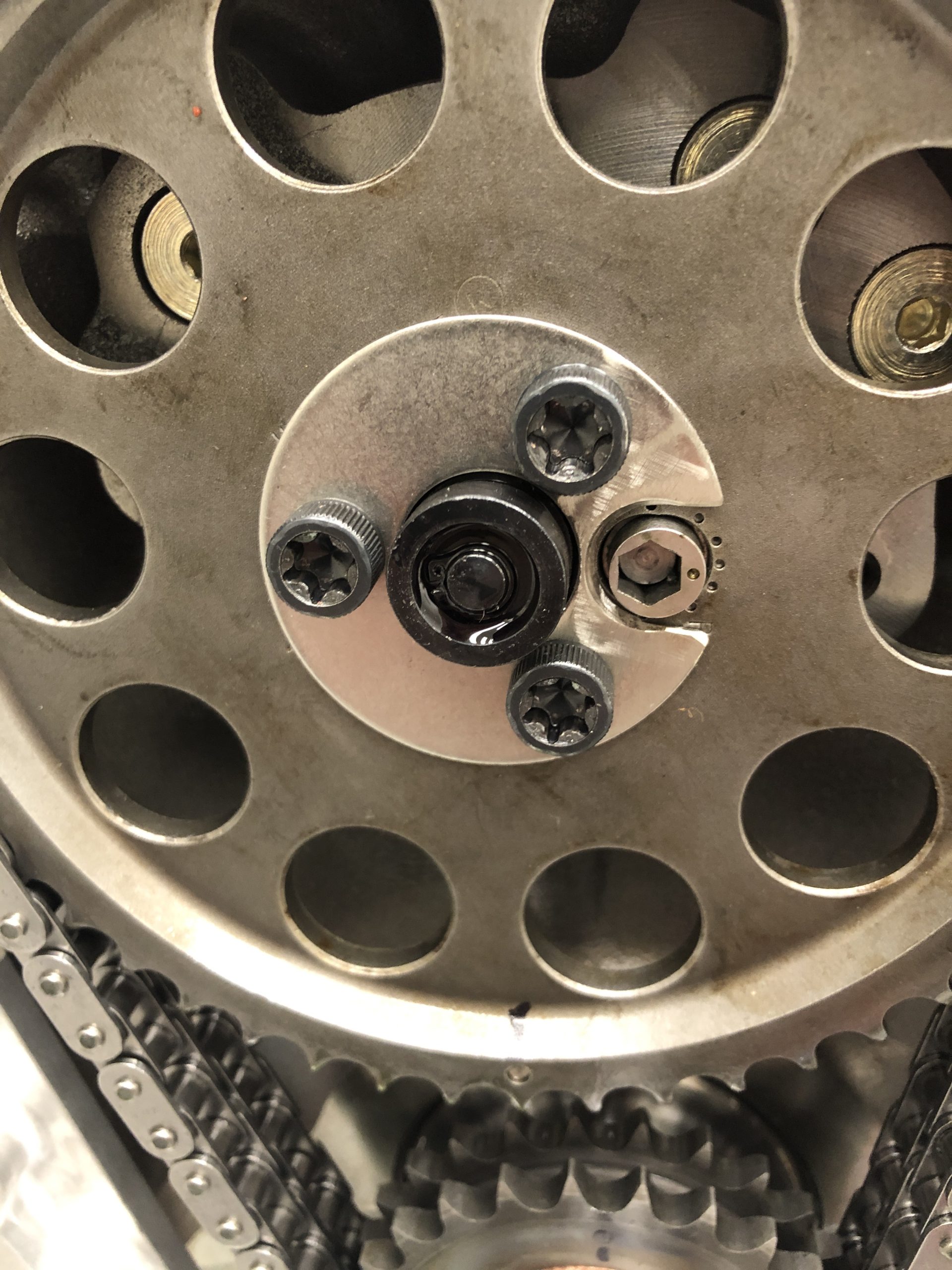
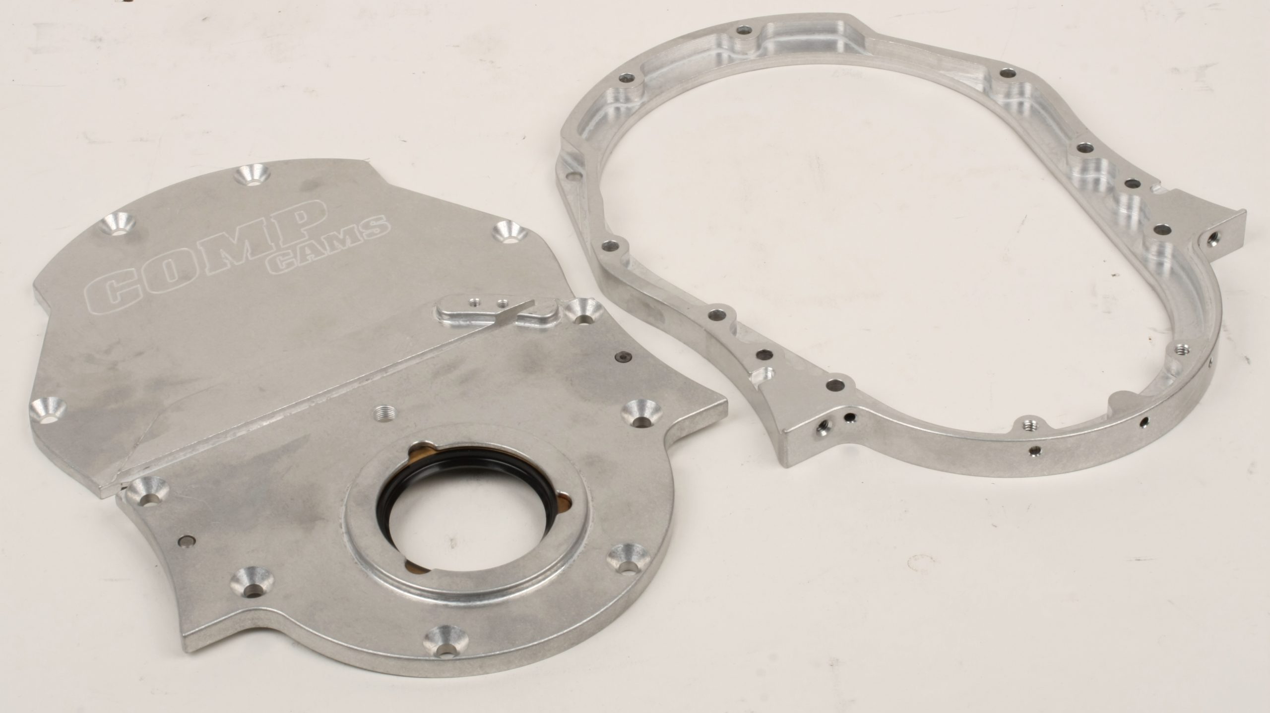
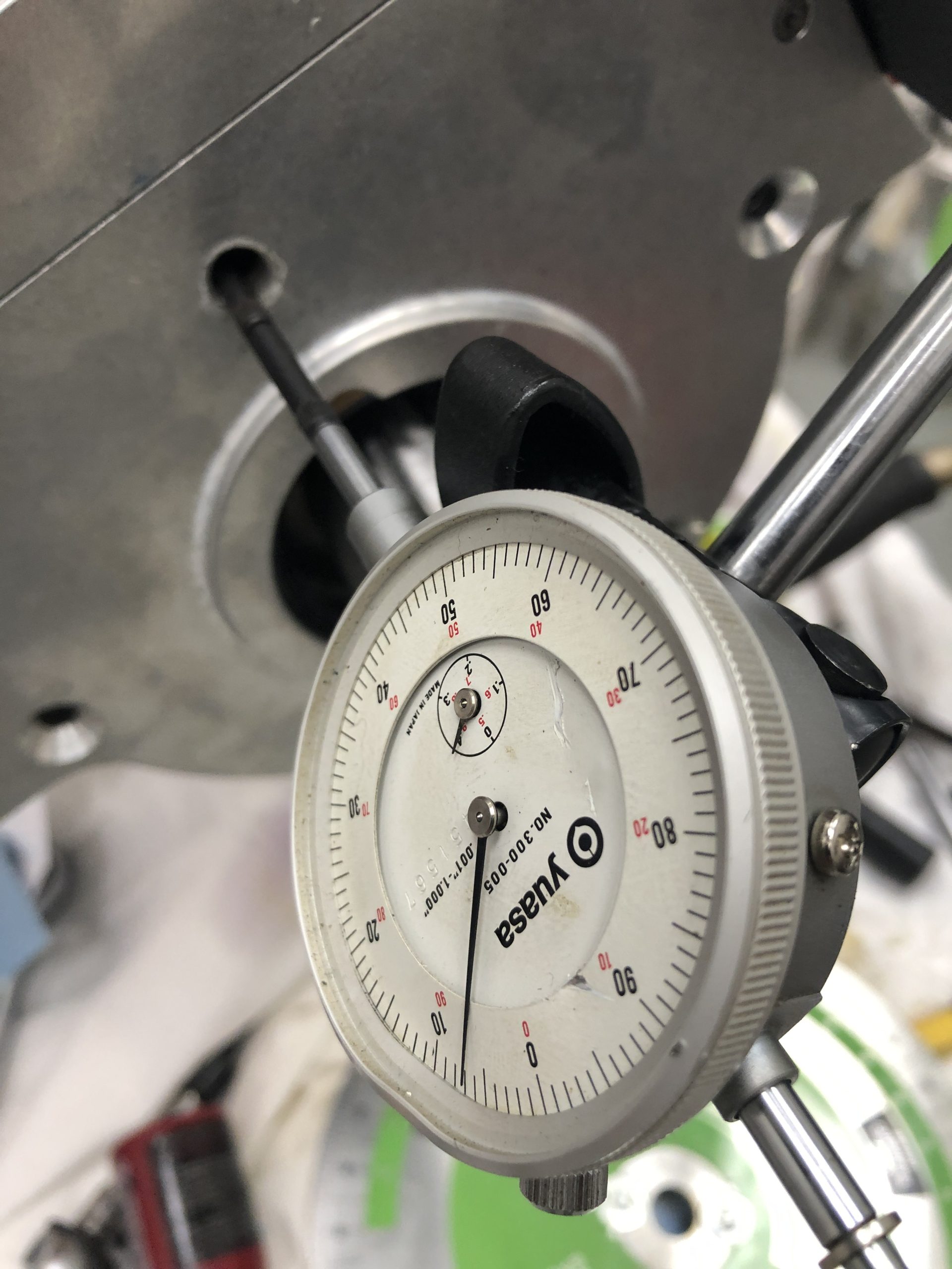
If a roller cam features a step in the nose, a retainer plate may be installed to prevent excess forward walk. If the cam nose does not feature a step, a thrust button is required to provide a forward thrust limit at the rear of the top timing cover. Since our cam is non-stepped, we used the roller thrust button included in our COMP Cams timing cover set. Shims in the kit are used to adjust the thrust button placement to keep cam endplay/thrust in the 0.005 to 0.010 inch range.
Our Cloyes Hex-A-Just timing set features an eccentric bushing that allows you to adjust cam advance and retard. I had to drill a hole in the thrust button retainer plate to clear the hex adjuster and reveal the timing reference dots on the cam gear.
The Cloyes timing set also features a Torrington thrust bearing that seats into a recess of the rear of the cam gear. If cam timing adjustment is needed, simply loosen the three gear-to-cam mounting bolts, adjust the eccentric, and retighten the screws to 25 ft.-lbs. with medium strength thread locker. Cam timing is adjustable up to six degrees advance or retard.
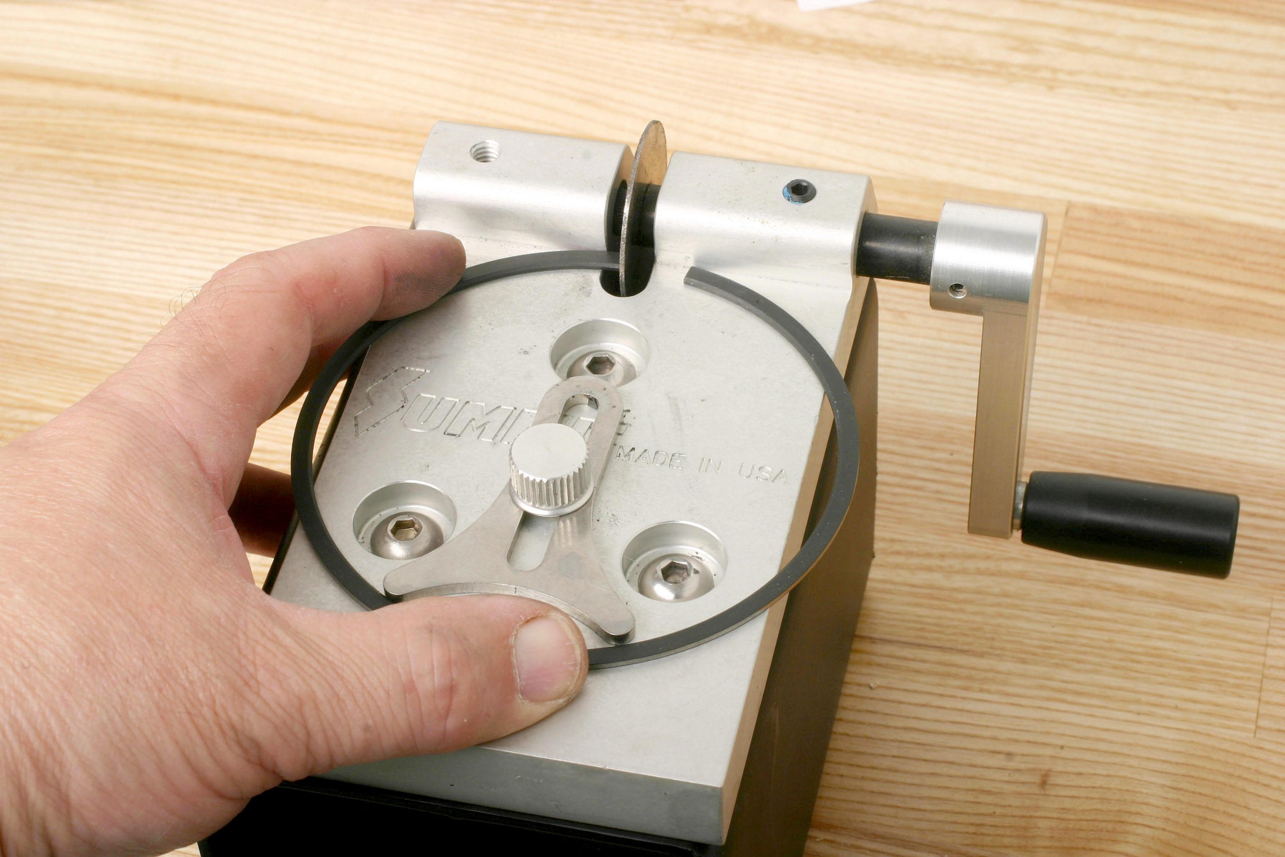
Piston & Connecting Rod Installation
The piston rings are a file-to-fit set from KB Pistons. Top ring gaps were filed to a gap of 0.020 inch and the second rings were set at 0.022 inch. The oil ring package (including support rails) were checked at 0.003 inch. The top and second rings were gapped on a per-cylinder basis and organized as such.
Since the piston pin bores intersect with the oil ring groove, a support rail was installed on the floor of each piston’s oil ring groove, with the anti-rotation male dot facing downward and centered to one end of the pin bore. The rings were installed with ring gaps clocked to prevent gap alignment. The rod bearing faces were coated with Royal Purple Max Tuff lube.
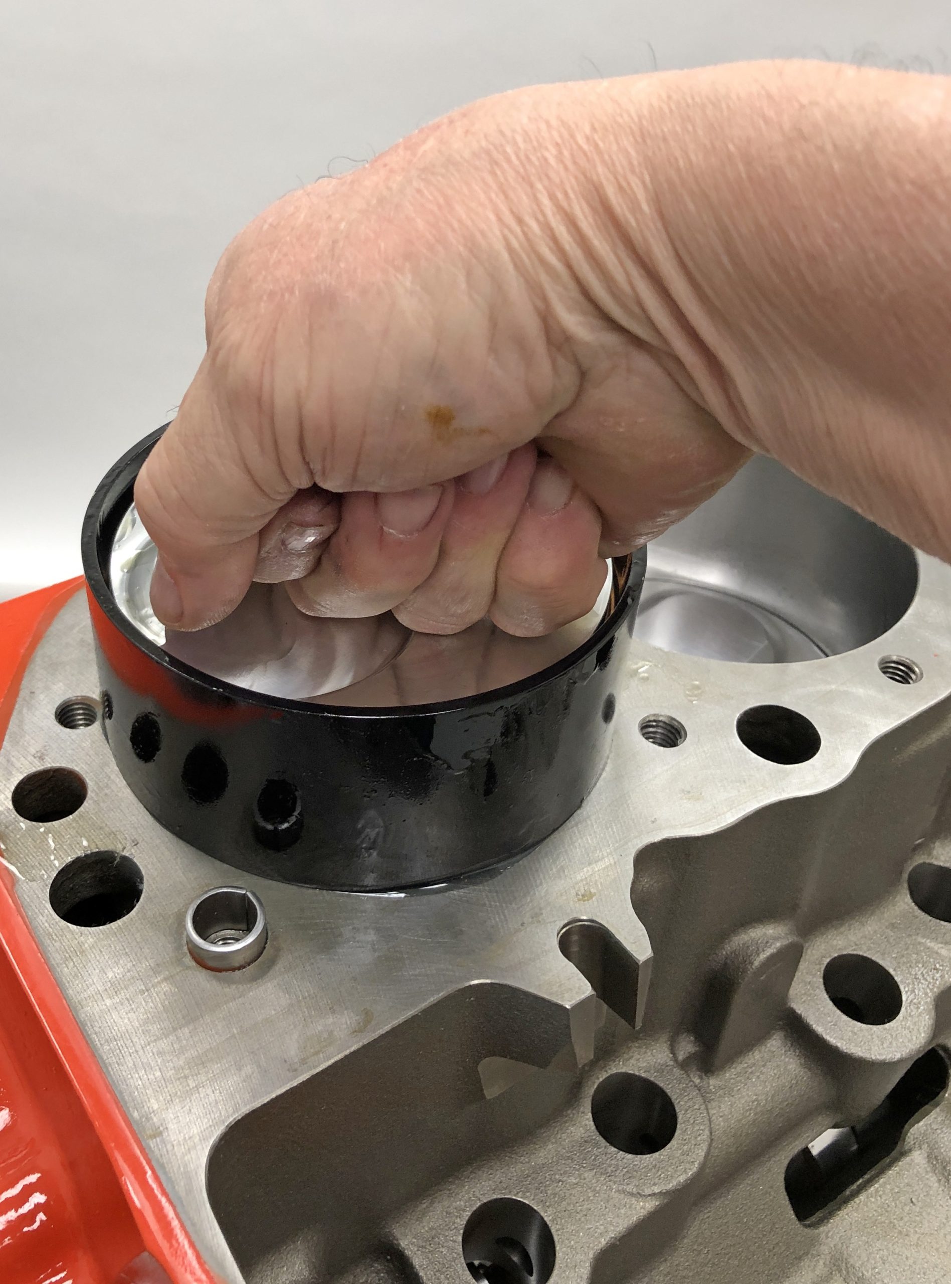
The cylinder bores were cleaned to remove any trace of contaminants. The cylinder walls, rings, piston skirts, and the inside of the ring compressor were coated with assembly lube. Each piston slid into the bores using hand pressure. Once the piston deck was just below the block deck, I used an extended-nose plastic hammer to gently tap the piston until the upper bearing in the rod made contact with the crank journal.
I carefully tapped rod caps into position on the rod’s upper dowels, then installed the ARP 2000 rod bolts. Scat warns against using the bolts to align onto the rod dowels. Before installation, I “seasoned” each bolt by torquing them three times to 40 ft.-lbs. in a rod vise using fresh lube.
Scat recommends a final torque of 70 ft.-lbs. for the bolts, with stretch not to exceed 0.0062 inch. Using a rod bolt stretch gauge, I observed an average bolt stretch of 0.0045 inch at 70 ft.-lbs. During final installation, the highest bolt stretch reading was 0.0046 inch.
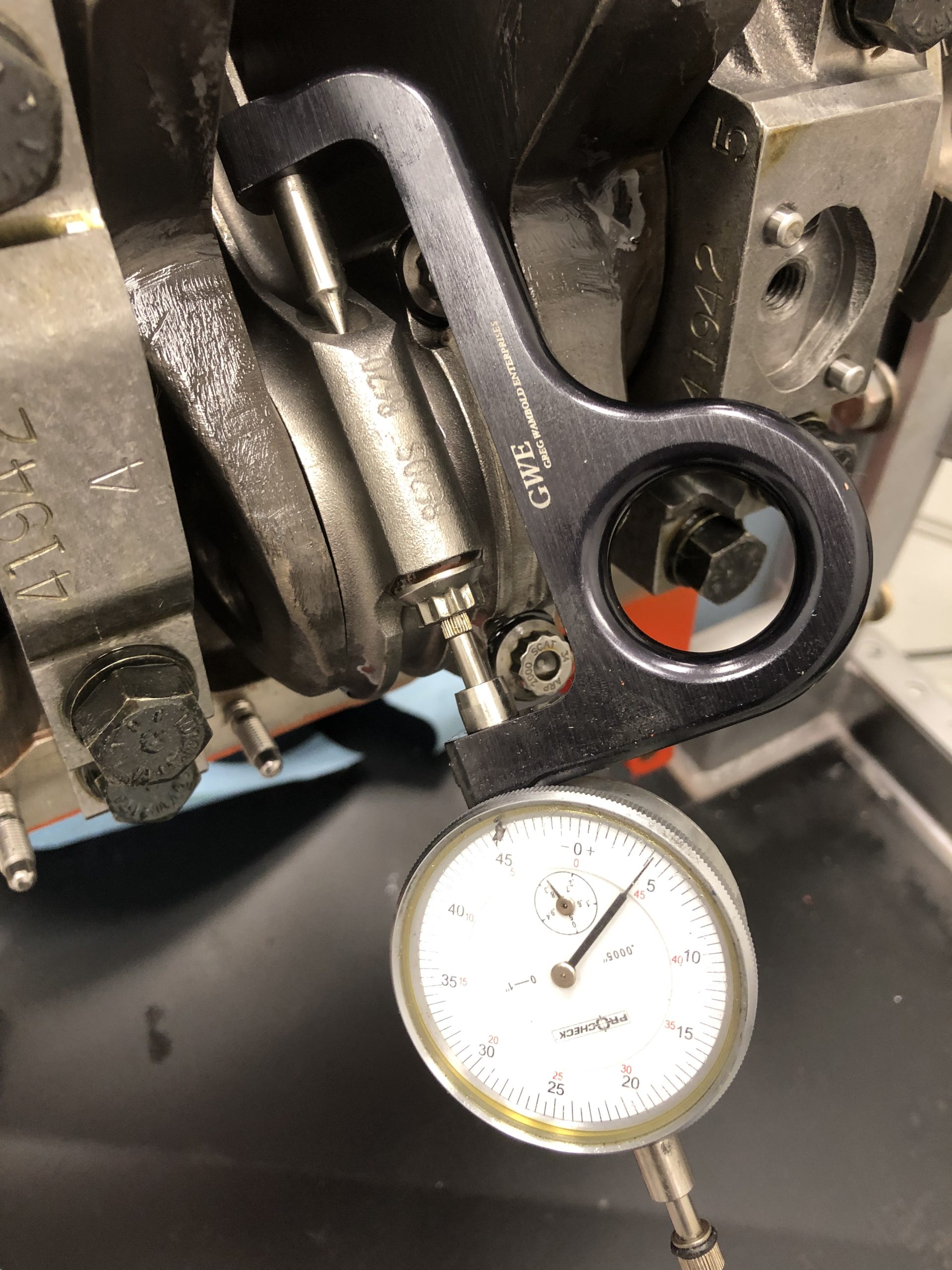
With all pistons in place, rotational torque was approximately 19 ft.-lbs. Rod sideplay ranged from 0.017 to 0.018 inch.
Next on the agenda for our 540 big block is the installation of the oil system, cylinder heads, and valvetrain. That’s all coming up in Part 2!
540ci Big Block Chevy Build Parts List (Bottom End)
- Dart Big M2 Engine Block
- Dart Block Hardware Kit with Cam Bearings
- Fel-Pro Rear Main Seal
- Scat Forged Crankshaft
- Scat Pro Sport Forged H-Beam Connecting Rods
- ICON Premium Forged Pistons
- KB Pistons Piston Rings
- Clevite H-Series Main Bearings
- Clevite H-Series Rod Bearing, standard (8 required)
- Clevite H-Series Rod Bearing, 0.001″ thinner (8 required)
- COMP Cams Timing Cover
- Royal Purple Max Tuff Assembly Lube

Comments