In last month’s Part One, we began our look at today’s piston technology. As mentioned in that article, the numbers of choices within the Summit Racing catalog are absolutely massive. There’s a lot to consider too. Piston design has evolved over the years, and thanks to the folks from MAHLE Motorsports we’re able to sort through many of the options and much of the technology (and it most certainly doesn’t apply to MAHLE pistons exclusively either). There’s something here for everyone. Check it out:
Piston Rings, Grooves & Lands
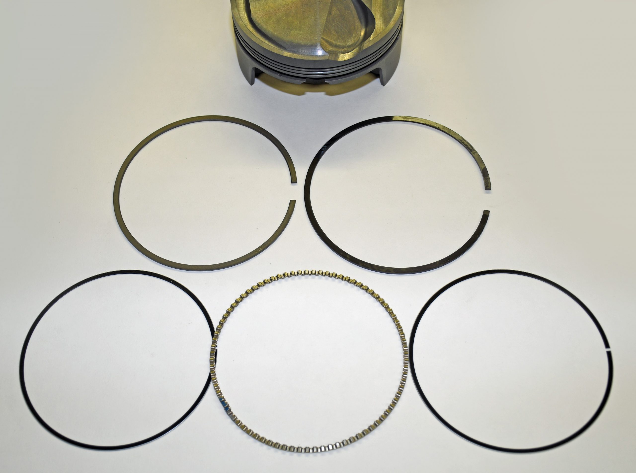
When it comes to the ring package, the most common piston arrangement makes use of three rings—compression, second, and oil. Two ring combinations (compression and oil) have seen success in drag racing, but for cars that see any street use, they’re the exception. The majority of MAHLE Motorsport pistons have ovality, and most have taper and or profile shape cut into the ring lands. The overall diameter of the ring land is smaller than the overall diameter of the piston, and in many cases, there is a small vertical taper present (see Part One’s section on piston skirts).
There’s a reason for this size differential: As the piston reaches top dead center, it “rocks” in the bore. If the ring land is the same diameter as the skirt, then the rings would be required to handle the thrust load (which they really don’t like to do). Instead, that job is left up to the skirt. MAHLE also notes another reason for the size differential is that the lands see more heat from combustion and therefore results in more expansion.
Another term you’ll encounter when considering ring grooves is “tilt.” In some pistons, the ring grooves will incorporate a positive “tilt.” This machining operation tilts the ring package upwards by a very small amount (in this sort of piston, the tilt is in the area of two to three ten-thousandths of an inch). In some applications, the “inclination” is important because it can improve ring seating. Ring groove tilt (inclination) is not purposefully machined into PowerPak pistons. Although MAHLE has the ability to machine inclination into the grooves, it’s something they don’t use on PowerPak pistons.
We’re not quite done with ring lands: The location of the ring grooves is often dictated by the compression height of the piston, the diameter and depth of the valve notches, and (as you might expect) the overall dimensions of the ring package. The intended application also enters the equation: Most common high performance V8 engines have the top ring 0.300 to 0.400 inch down from the deck surface. In an endurance racing engine, the top ring is typically down 0.125 to 0.150 inch, and heavily modified race engines (for example, a drag race Pro Stock or Comp Eliminator application) can vary from 0.060 to 0.100 inch down from the deck (although 0.060 inch is likely cutting things close). Moving the top ring upward offers a number of advantages, not the least of which is minimizing the “dead air” space between the top ring land and the deck. As this space is reduced (by moving the ring up), the amount of trapped combustion gasses is also reduced. The combustion process is cleaned up considerably when the rings are moved upward and that, of course, adds power.
The Space Between Piston Ring Grooves
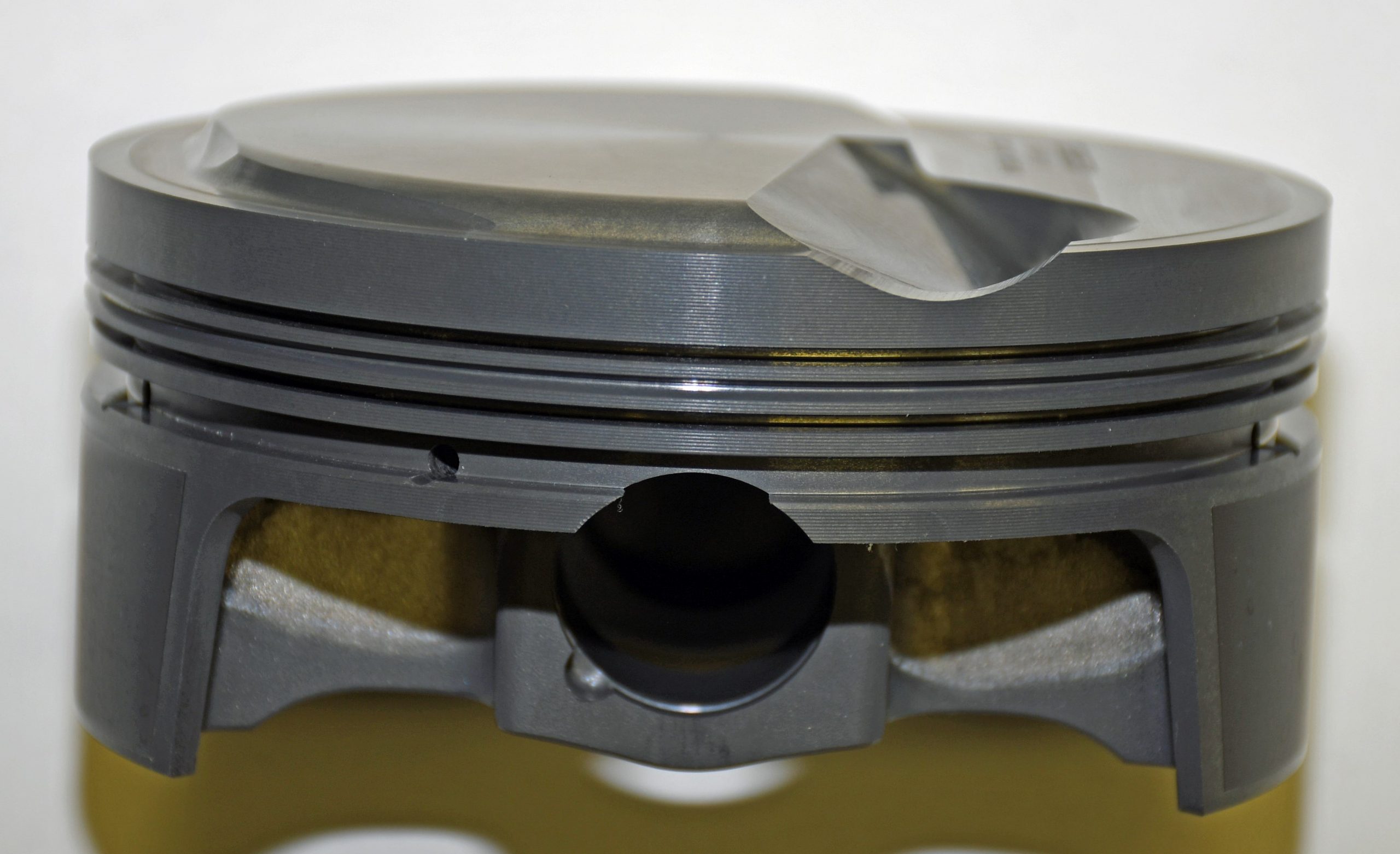
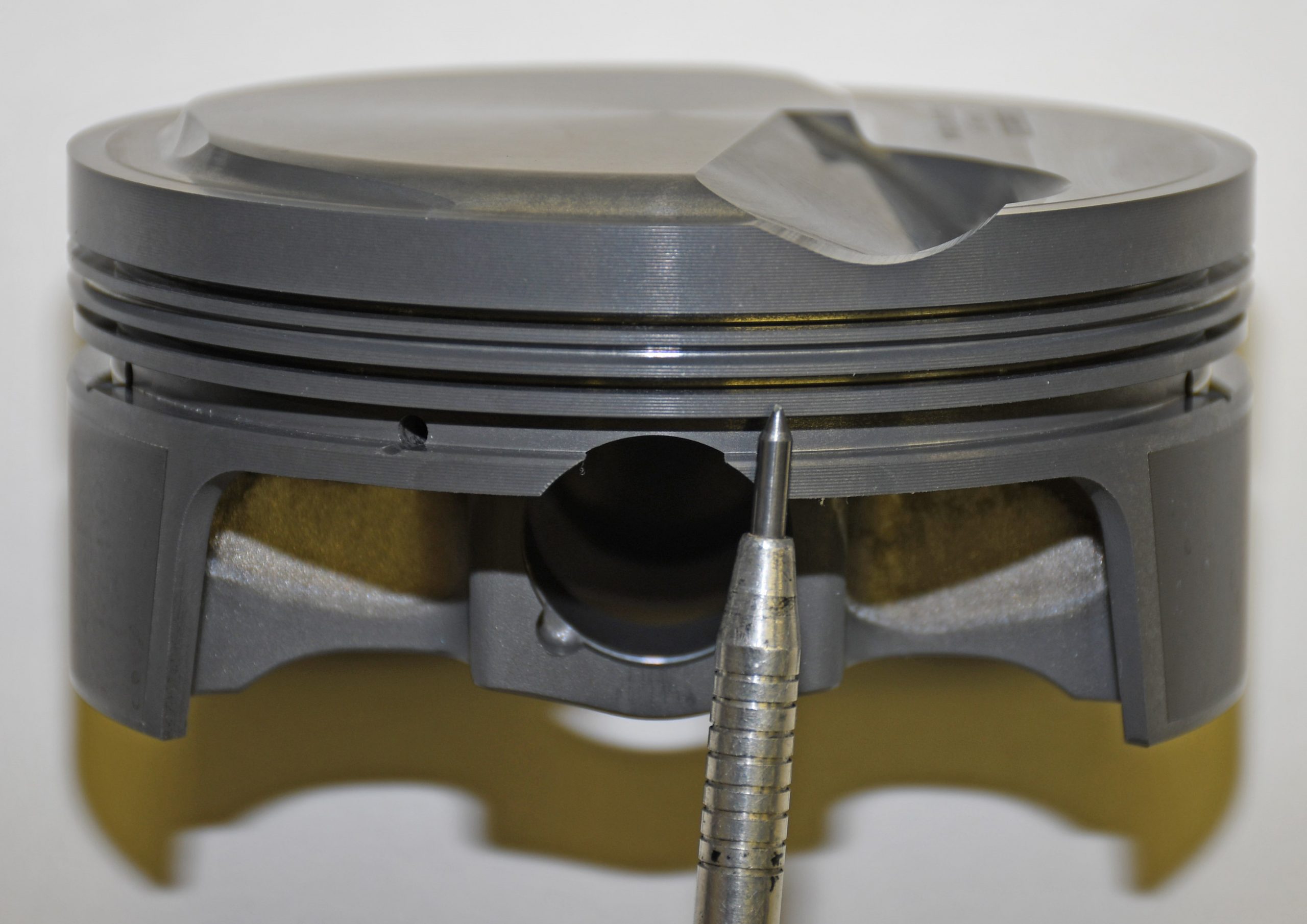
It’s also important to consider how much piston material is between the rings. Although the location of the second ring isn’t as critical as the distance from the deck to the top ring, it’s still important. The second ring doesn’t see temperatures anywhere close to that encountered by the top ring, but the land between the top two rings is still faced with supporting the combustion pressure exerted upon the top ring. Due to this, the width of the second land area is typically between 0.150 to 0.180 inch in a high-performance piston and greater in a stock application. When you consider the land area between the second and third ring, many high performance and race pistons maintain a width of between 0.070 to 0.125-inch. This is narrower than the second land, but keep in mind that combustion pressures aren’t present and overall temperatures are much lower. We should also note some pistons incorporate “stepped” lands. This means that the land area between the top and second rings is slightly smaller in diameter than the area between the second and oil rings.
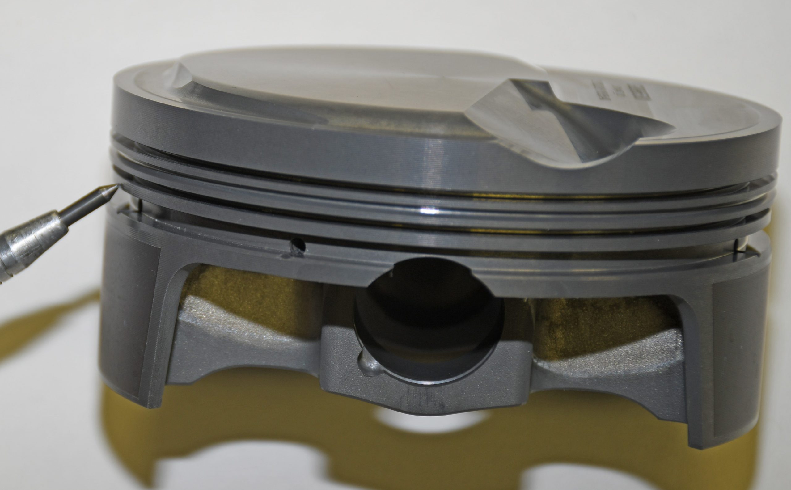
Some high performance and race pistons incorporate a groove machined into the land area between the top and second ring (some manufacturers ball mill the groove—MAHLE Motorsports uses a V-shaped groove). This groove is often referred to as an “accumulator groove.” It’s designed to reduce pressure buildup between the top two rings. The idea here is the accumulator groove will stop the top ring from lifting at the bottom of the groove. The groove effectively maximizes ring seal and increases engine vacuum.
Oil Drain Back
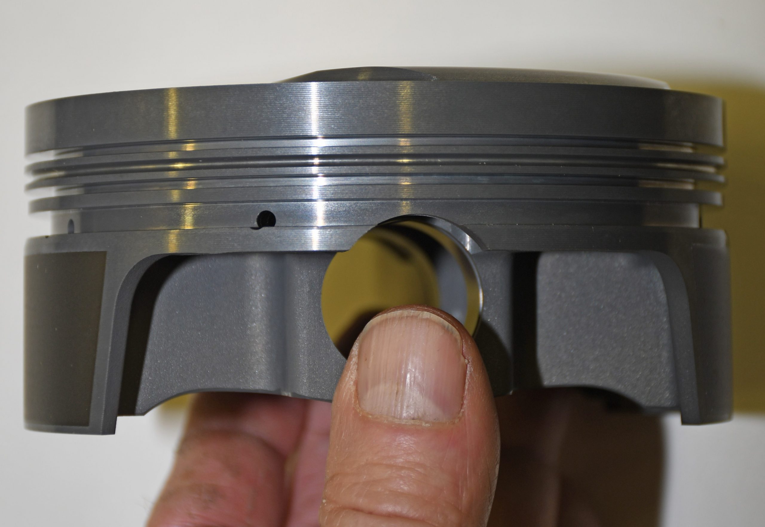
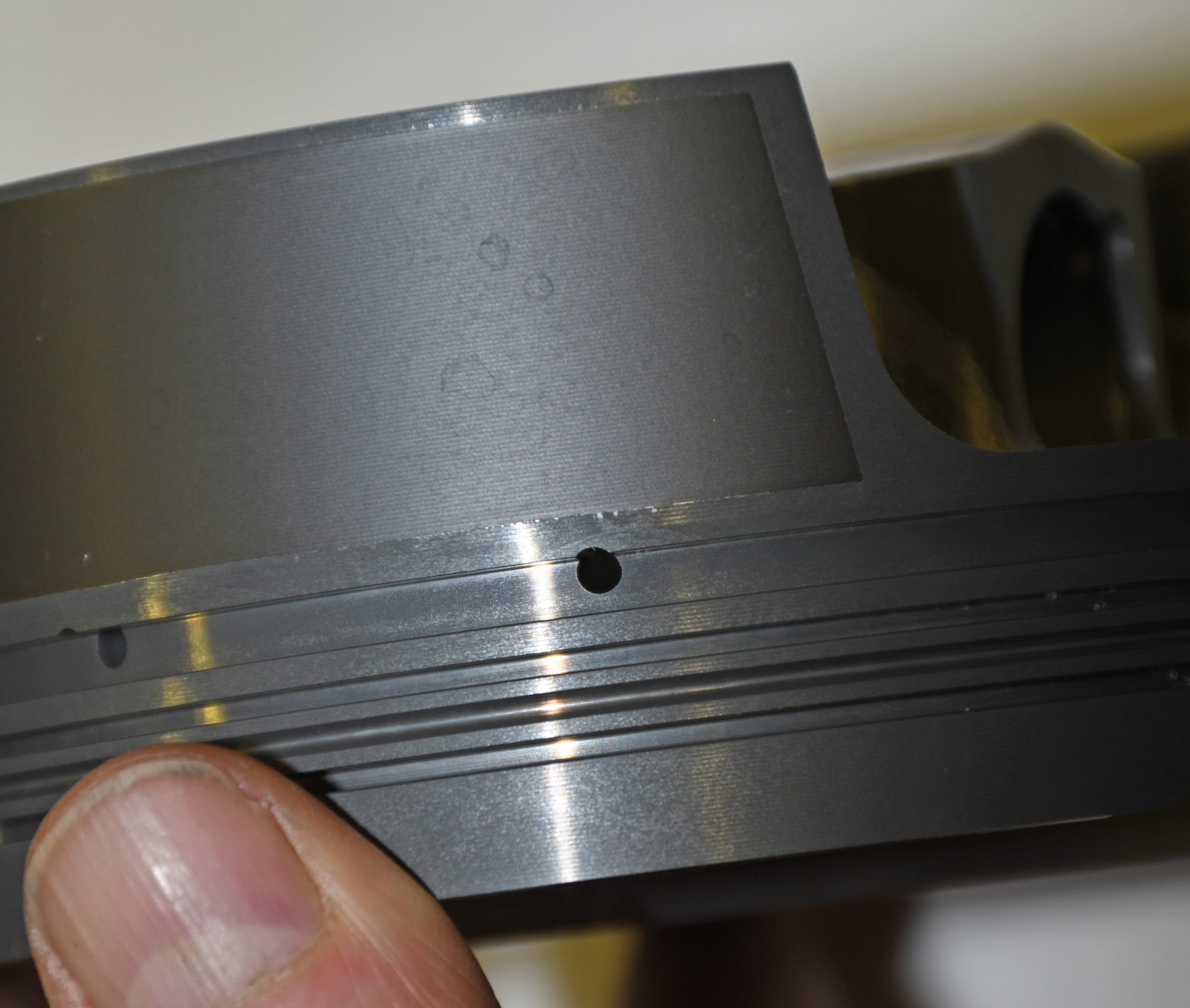
Two different types of oil drain back holes have commonly been used in pistons: drilled holes and slotted grooves. The use of slots is old technology typically found in vintage cast pistons. Most race and high-performance pistons are constructed with drilled drain back holes. Obviously slotted grooves can make for a more flexible skirt.
With the MAHLE Power Pak piston round drain back holes machined into their pistons are actually lower in the ring groove than on some other piston designs. In fact, the drain back holes are actually lower than the lower oil ring scraper. What this does is to force some of the oil to drain back on the cylinder wall.
Clearances Between the Piston Ring & Groove
The clearance dimension between the ring groove and the piston ring is critical. Ring grooves must be smooth—and the smoother and flatter the manufacturer can get them, the better. According to MAHLE, “a flat ring groove is essential in achieving and maintaining the best seal possible. The quality of the ring grooves is so critical to peak and lasting performance, that MAHLE designed and built the machinery used to machine the ring grooves for MotorSport piston assemblies.”
Here’s why those ultra-flat grooves are critical when it comes to the compression ring: Through the compression stroke, the ring drops to the bottom of the groove, sealing against the machined surface. Through the power stroke, the piston moves down in the bore. The ring migrates upward in the groove, eventually sealing against the top of the machined surface. A poor finish in the groove will not allow the ring to seal tightly. Due to this, the pressure will leak past the rear (back) portion of the ring. Evidence of this leakage is excessive heat discoloration or carbon buildup in the area between the top and second ring lands.
Something else that affects ring seal is the vertical clearance of the ring. A race piston usually never exceeds 0.002-inch vertical clearance while production line street engines regularly have clearance figures between 0.002 to 0.004 inch. More than that and the ring will leak. Less than that figure and there’s a risk of seizing the ring in the groove. If the ring cannot turn freely, it will not clean carbon out of the groove. As a result, it will not be free to expand when combustion pressures enter the groove.
A piston constructed with tight vertical clearances also means the ring back clearance figures become crucial. Gas pressure enters the area behind the ring during combustion, forcing the ring outward against the cylinder wall. Too much back clearance creates too much volume for the combustion gasses to fill. As a result, it takes too long for the pressure to build and force the ring outward. A lesser amount of back clearance increases the speed and force at which the ring will exert pressure upon the cylinder wall. Production line engine pistons typically have as much as 0.040 to 0.050 inch of back clearance. In a race or high-performance application, the backside clearance figure is often reduced to as little as 0.020 inch or less (this is dependent upon the ring configuration as well as the piston design). The back clearance can’t be so small that the ring protrudes beyond the ring land.
Gas Porting
One exception to vertical clearance is when gas ports are used in the piston. Gas ports provide a means to supply combustion pressure directly to the backside of the piston ring. As a result, ring vertical clearance can be reduced, and simultaneously, ring flutter can also be reduced significantly. Ring seal goes up along with horsepower. Unfortunately, gas ports are only suited for use with engine combinations where frequent teardowns are common. This means gas ports don’t see use in street-driven vehicle applications. Carbon tends to plug the gas port holes and ring and cylinder wall wear is much faster than more conventional setups.
Typically gas ports consist of 12 to 16 0.040 to 0.060-inch holes drilled vertically through the piston deck. They intersect with the backside of the compression ring groove. Gas porting is most advantageous when a narrow face, lightweight piston ring (such as the 0.043-inch ring) is used. MAHLE uses a different setup. They make use of lateral gas ports, consisting of 8 to 12 horizontal holes drilled into the top flank of the top ring groove. This allows combustion gases to the backside of the ring groove. MAHLE notes it can add vertical ports on a custom basis, but it primarily provides lateral gas ports (they’re an option on a select few pistons in their PowerPak lineup).
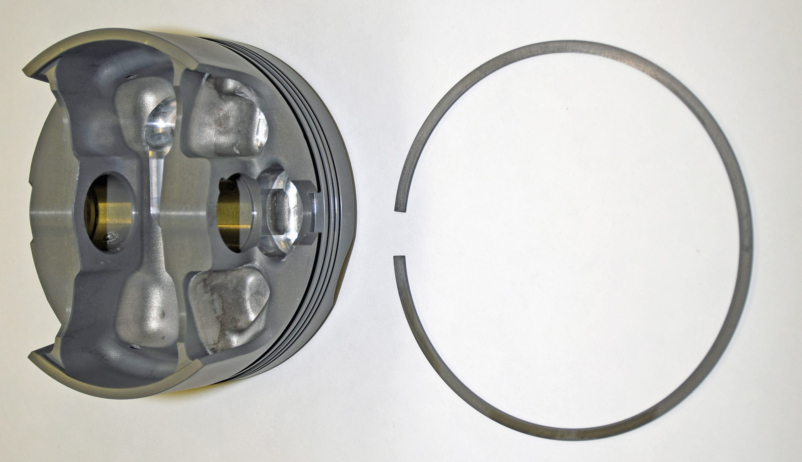
Selecting the Right Piston & Ring Package
According to MAHLE: “The super flat ring grooves provide for consummate ring sealing, oil control and ring longevity. Each PowerPak piston kit includes either a low drag 1.0mm, 1.0mm, 2.0mm ring set, a 1.5mm, 1.5mm, 3.0mm ring set, or a 1/16 inch, 1/16 inch, 3/16 inch high-performance ring set, dependent upon the application.”
MAHLE Motorsports PowerPak pistons are available for a wide array of engine combinations (import and domestic). They’re perfect for sportsman racing applications or general high-performance use.

Comments