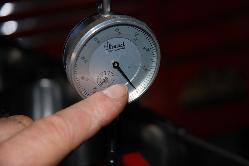
This dial indicator has been set up to read component runout and zeroed. That means the plunger has been run down part way through the range of travel. Once that is accomplished, the outer dial bezel is rotated to position a zero mark directly on the large needle. You can see here that the photo was taken slightly to one side. It shows the effects of not reading a gauge straight on. (Image/Wayne Scraba)
One of the most important tools you’ll find in any racer or rodder’s tool collection is a dial indicator.
They’re used for everything from degreeing a cam to checking run-out on a disc-brake rotor (along with any number of tasks in between).
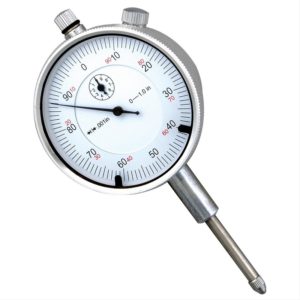
Summit Racing offers all sorts of different dial indicators in all sorts of price ranges. This inexpensive Summit-brand dial indicator reads from 0-1.00-inch and as you can see, the gauge reads in 0.001-inch increments. (Image/Summit Racing)
The most common dial indicators make use of a calibrated stem fitted with a moveable spindle or plunger that transfers linear motion to an easy-to-read dial face.
Dial faces are commonly marked in 0.001-inch increments, which means that one complete revolution of the indicator needle equals 0.100-inch travel or one-tenth of an inch.
Typically, the dial indicator will incorporate what is called a “short hand” on the face. This is a much smaller calibrated dial with markings for every tenth of an inch so you don’t have to visually count the number of full revolutions the needle makes.
Given that there are specialty indicators out there that read (for example) 0.050-inch per revolution, it’s good practice to note the spec on the gauge face to be sure you read the hash marks correctly (most gauges have a spec on the face, but some don’t).
When using a dial indicator, you must be absolutely sure that it’s stable and mounted rigidly. If the indicator moves, the measurements won’t be accurate.
This is why dial indicators are almost always used in conjunction with an adjustable magnetic base that can be clamped (solidly) to an adjacent surface.
In use, the magnetic base can be adjusted to position the dial indicator so that it can read movement in the appropriate direction.
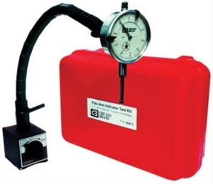
Here’s another dial indicator kit from Chicago Brand tools. This version incorporates a 0-1.00-inch dial indicator along with a flex arm stand. It is magnetic and incorporates an on-off switch. (Image/Summit Racing)
Depending on how the indicator is set up, it can read travel in either direction.
To accomplish this, you must position the dial indicator so that the plunger is parallel to the direction of component movement. Now, the dial indicator plunger is positioned approximately halfway within the range of travel.
Next, the dial indicator must be zeroed.
To do so, rotate the outer dial bezel and position the gauge zero mark directly on (over) the large needle, regardless of where it’s pointing.
Once the dial indicator is zeroed, you can take measurements by moving the target part through its range of travel.
The dial indicator will show movement either positive and/or negative. Always be sure to read the dial face straight on for the most-accurate reading.
Using a dial indicator isn’t very difficult and it’s easy to find dial indicators for any budget.
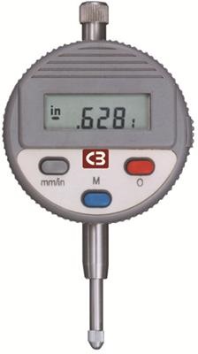
There are also digital readout dial indicators. Here’s another Chicago Brand tool. These electronic digital indicators also read to 0.0001-inch with 0.0005-inch accuracy.
“Last Word” dial indicators require a correction factor in most instances. Read the accompanying directions with each indicator.
[…] video also shows how to measure a brake caliper using a dial indicator, for a more accurate assessment of its […]
[…] the plunger. The dial itself has a scale and an indicator body. Above the scale lock, there is a needle that moves. Turning the outer scale for calibration is possible by loosening the scale […]
I find your articles to be very informative for both the novice and the beginner As well as a professional thank you for what you do