Whenever considering an EFI swap on a vintage engine, or swapping in a late model motor, there are many puzzle pieces that must come together. Most EFI conversion kits out there will set you up with just about all the hardware required to make it happen, but there is always one critical component that is missing: the fuel tank.
If your project is among the most popular nameplates in vintage steel (such as Mustang, Camaro, Chevelle, Tri-Five Chevy, Nova, F-Series, C-10, and so on) then you’re in luck. If you’re building a classic with that kind of support, life is good. You can dial up a manufacturer and get a brand-new bolt-in EFI fuel tank with an in-tank fuel pump or even a drop-in module that will work with your original tank.
But what about the rest of us? There are so many interesting and unique classic cars out there that don’t have any support for retrofitting an in-tank EFI pump, baffle, and a return line.
For those cars, it still feels like the old days of EFI retrofitting. Historically, most EFI retrofits ended up running an external electric fuel pump on the factory fuel pickup because there were only three options to get an in-tank pump—none of which were easy. You could weld a sump into the original or a replacement style factory tank, adapt a fuel cell, or open your wallet wide and pay for a custom tank.
Why You Need to Upgrade Your Fuel Pump for EFI
Before we go any further, let’s answer the question that we know is on your mind:
What’s wrong with an external fuel pulling from the factory fuel pickup?
That set up will work, but we can tell you about the pitfalls firsthand because we did exactly that for a few years on our project. Most of the issues revolve around the fact that vintage fuel tanks don’t have internal baffles or sumps to keep fuel around the pump pickup. This means that once the fuel level gets below a certain point, the fuel slosh that happens with pretty much any instance of hard braking, acceleration, or cornering is likely to uncover the fuel inlet and suck air into the electric pump causing an instant loss in fuel pressure and power. You can minimize these issues if you keep the fuel level high, but we’re not the best at always keeping the fuel at half tank or above.
The other common issue we encountered was fuel pump cavitation (aka vapor lock), as evidenced by the loud gravelly rumbling sound coming from the pump accompanied by a loss of power and erratic idling. Cavitation occurs when liquid fuel literally vaporizes (boils) inside the pump assembly and is commonly caused by high heat, high inlet restriction, or excessive fuel turbulence. In our case, it was heat and turbulence from sloshing fuel. Modern fuel can boil as low as 100 degrees Fahrenheit, which is one key reason all modern fuel systems use an in-tank fuel pump. Bathing the pump in fuel keeps it running cooler than it would if it were externally mounted and is the primary reason that vapor lock is rare in modern fuel systems. And of course because they’re dramatically quieter.
Meet the Aeromotive Phantom 340 Fuel System
Back to the solution! Since our project doesn’t have any custom tank options, we’re turning to Aeromotive’s Phantom 340 fuel system since it will solve all our issues in one fell swoop. The Phantom system’s internal baffle/basket controls fuel slosh and keeps the fuel pump submerged in fuel, even at low fuel levels and during aggressive driving. The best part about this whole system is that its completely universal. It will fit virtually any tank from 6 to 11 inches deep, plastic, steel, aluminum, corrugated or smooth. Simply cut a hole in your tank, measure the depth. cut the pump hanger bracket and foam baffle, insert the baffle, install the retainer ring and gasket, and bolt your pump and hanger down. That’s it! Now, let’s take a closer look at those steps.
Summit Racing Remote Rollover Vent Valve – SUM-220019
***
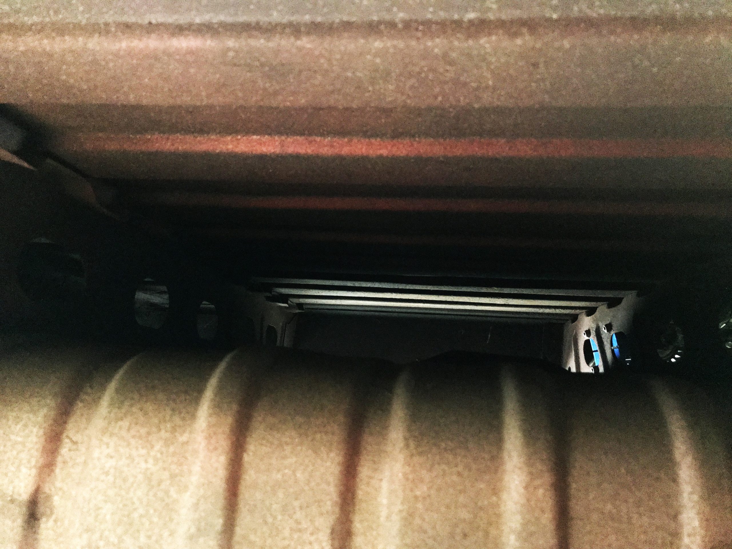
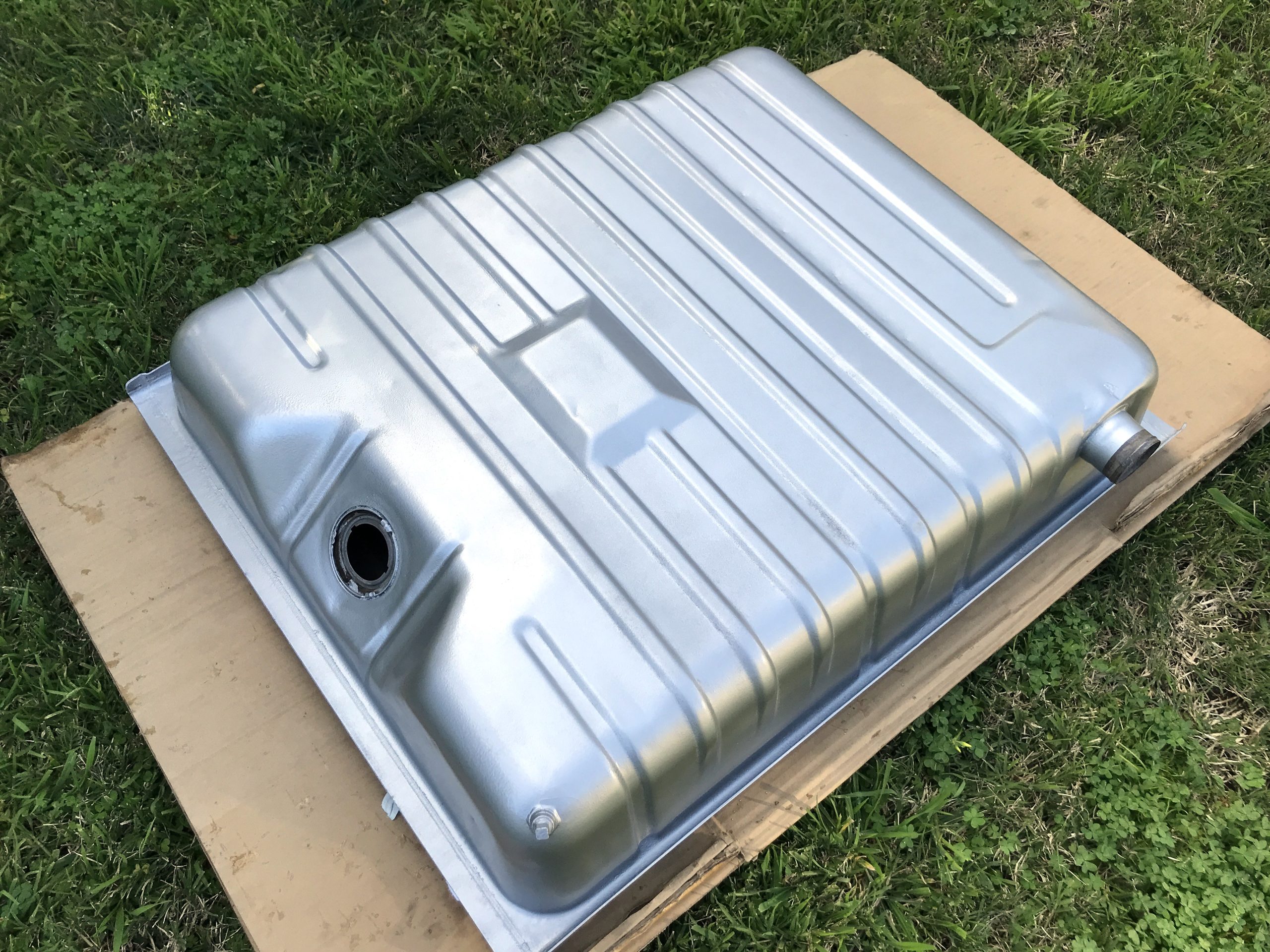
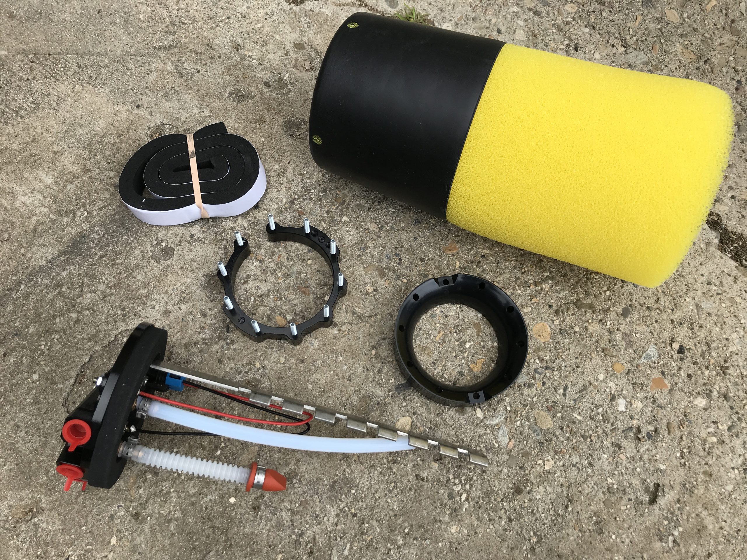
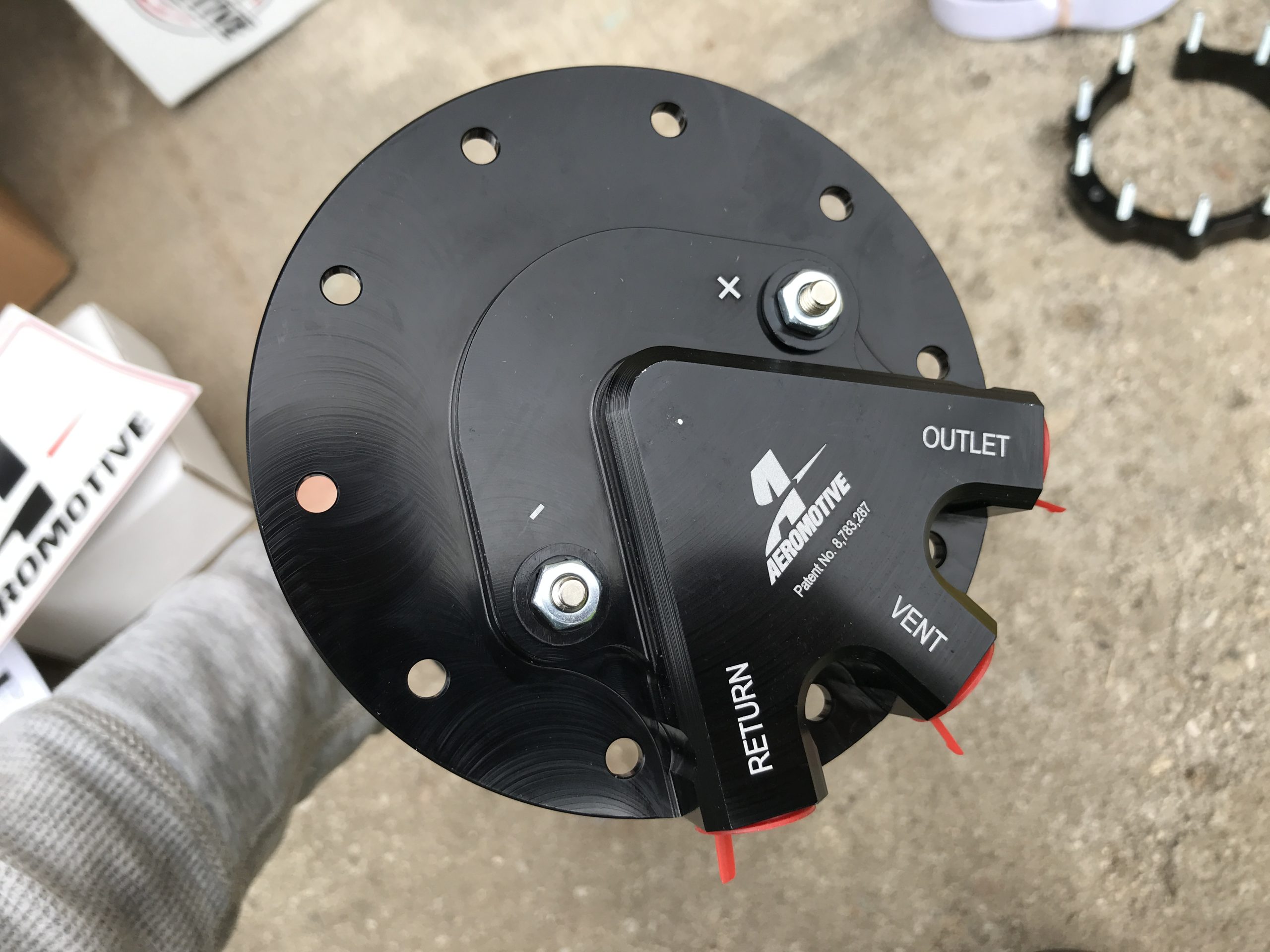
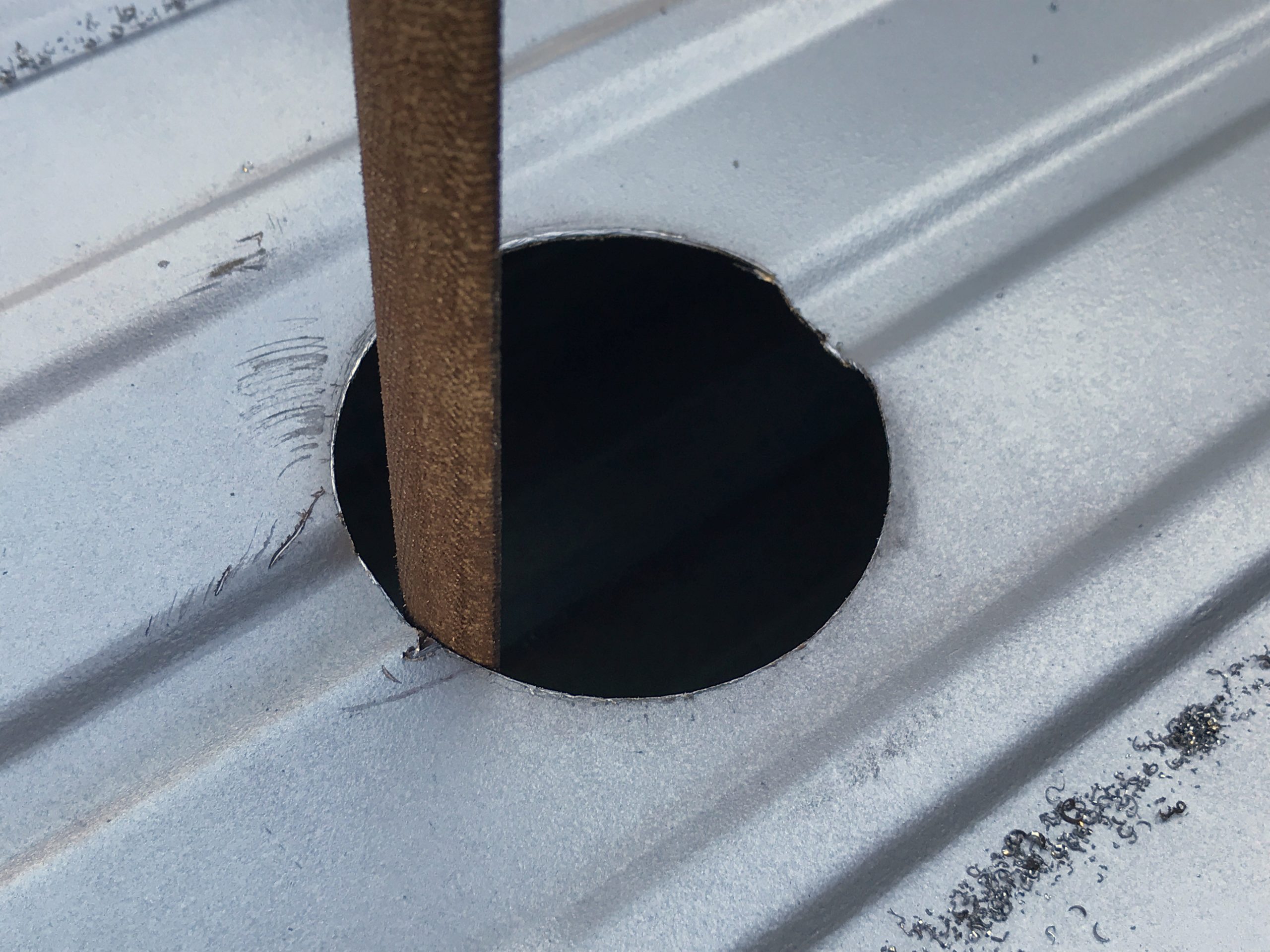
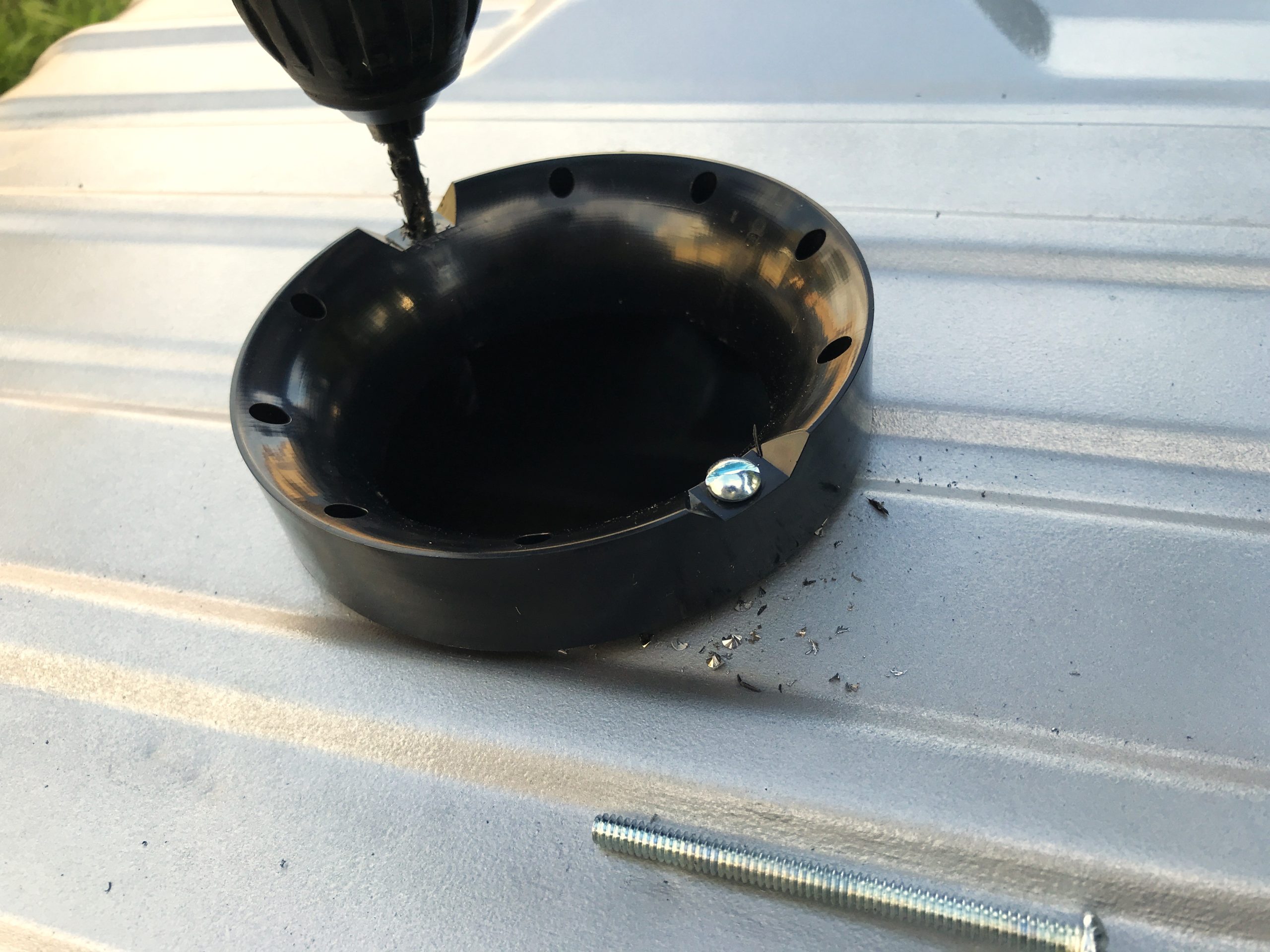
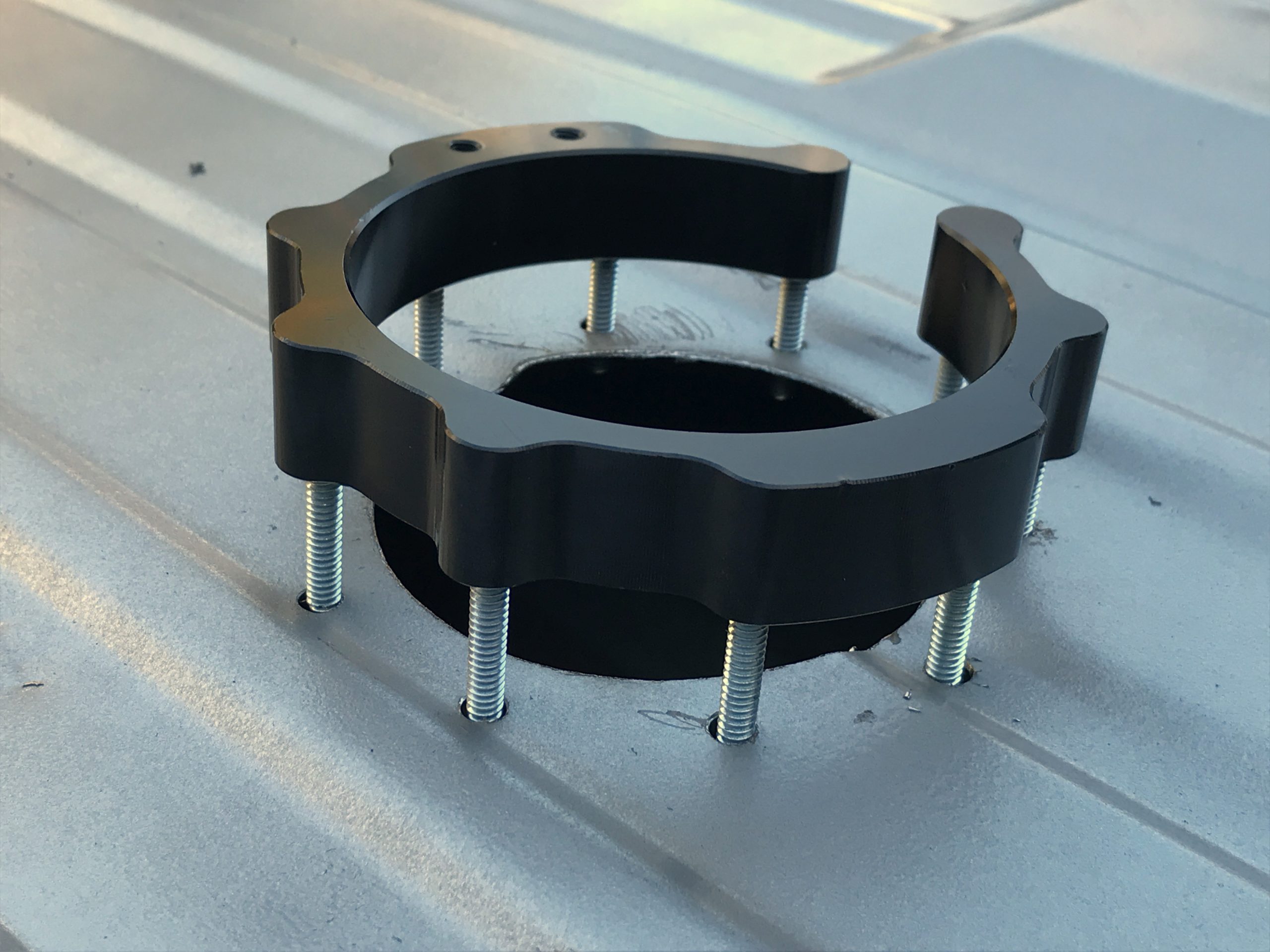
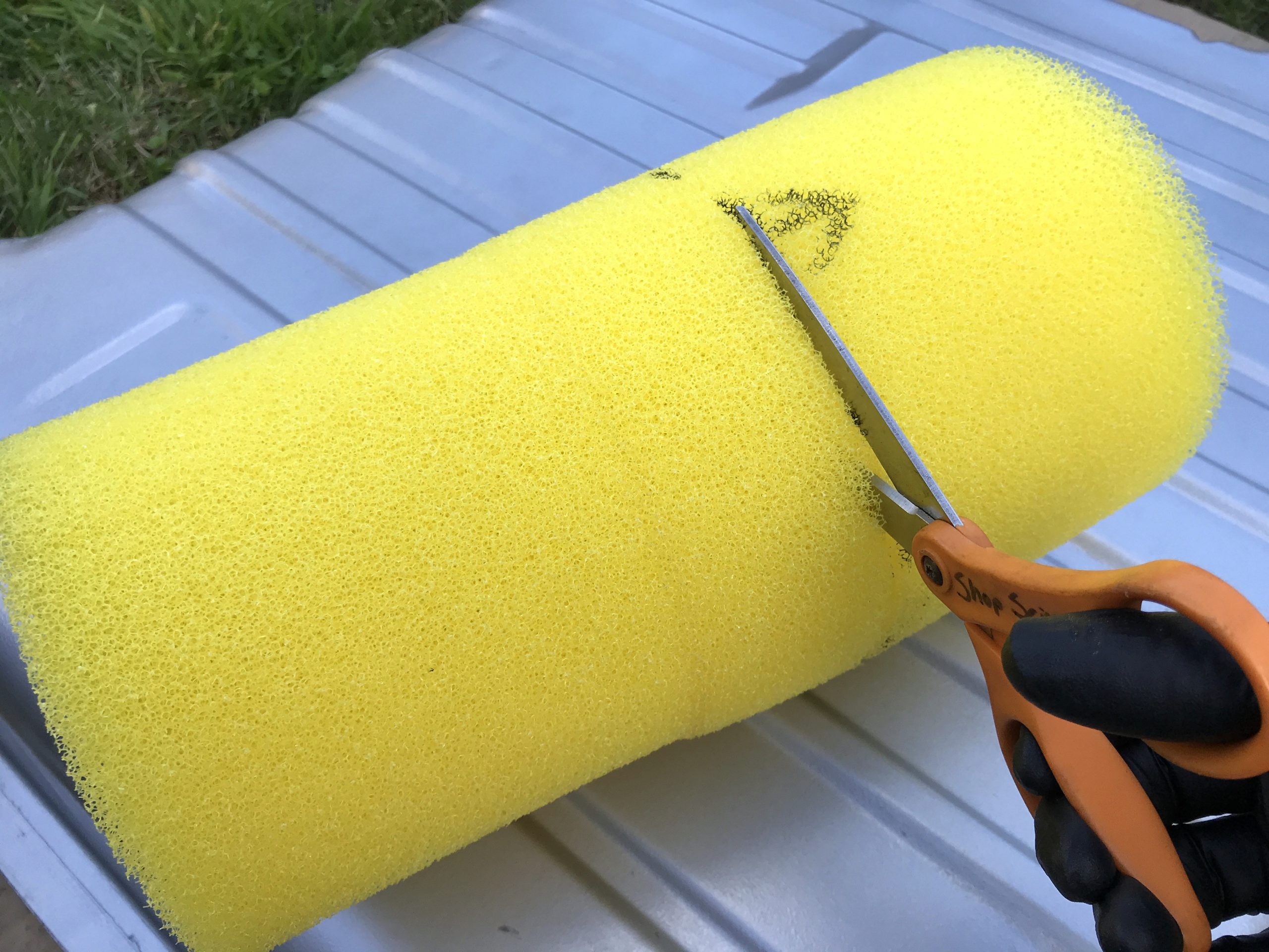
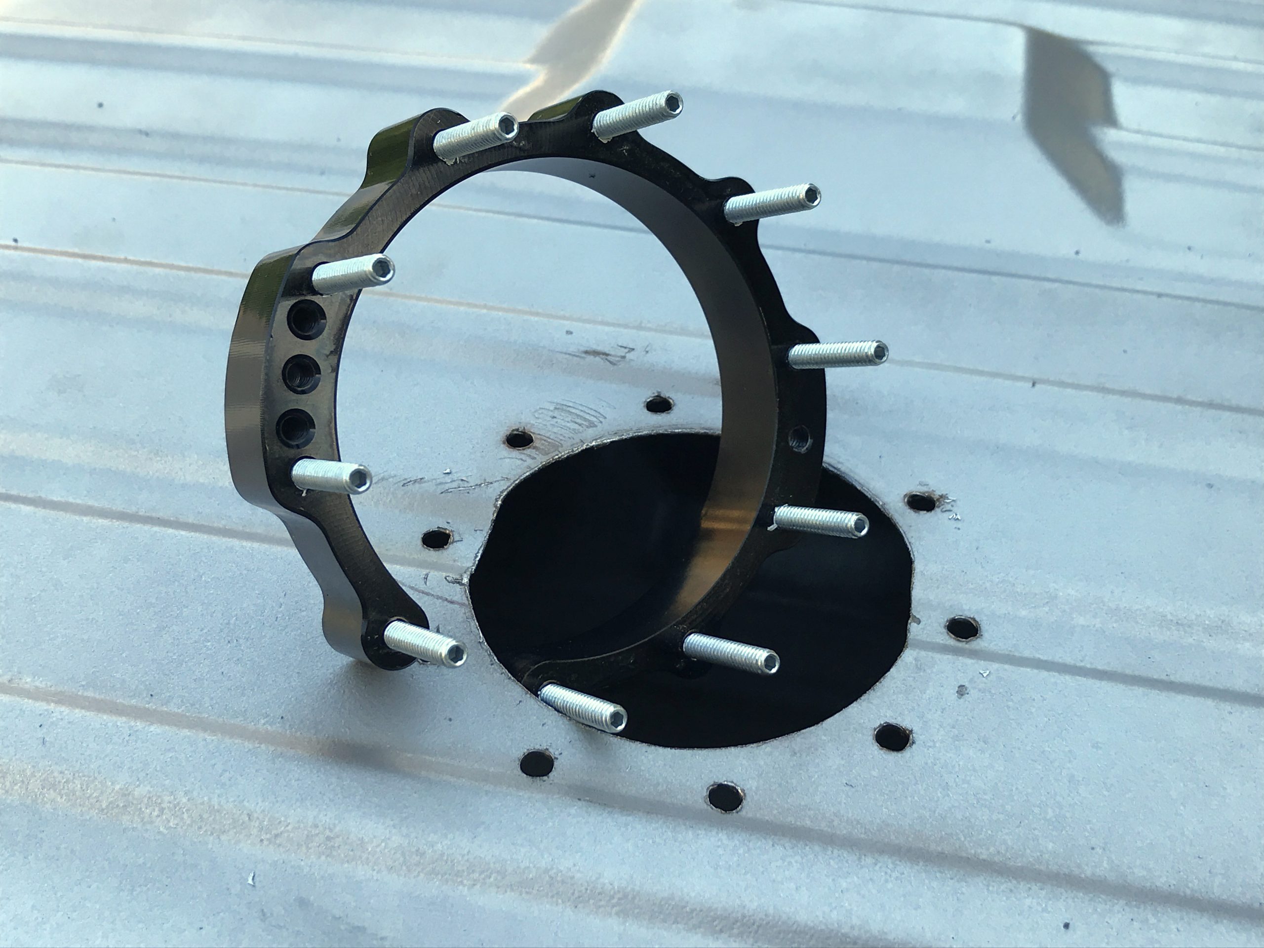
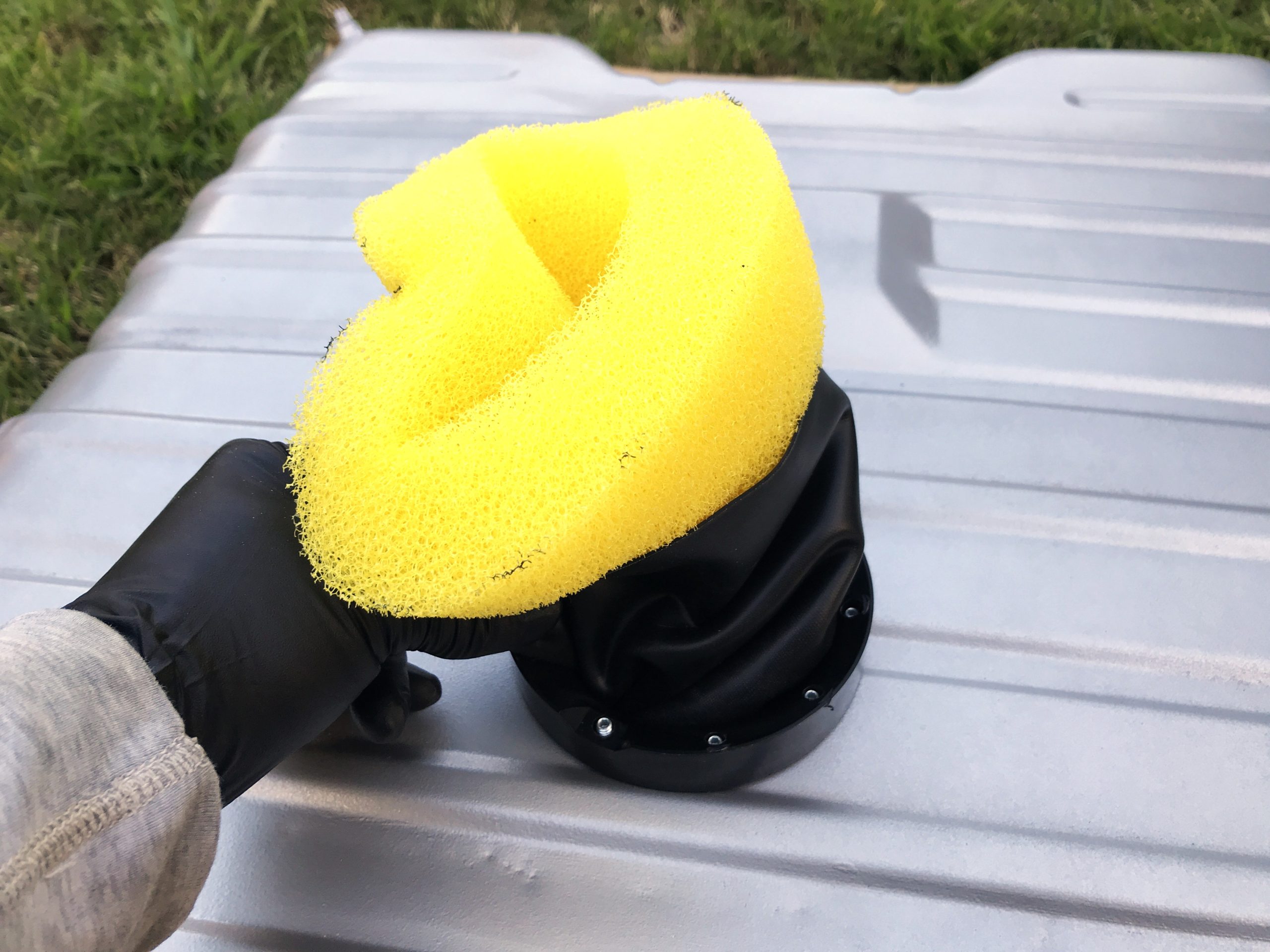
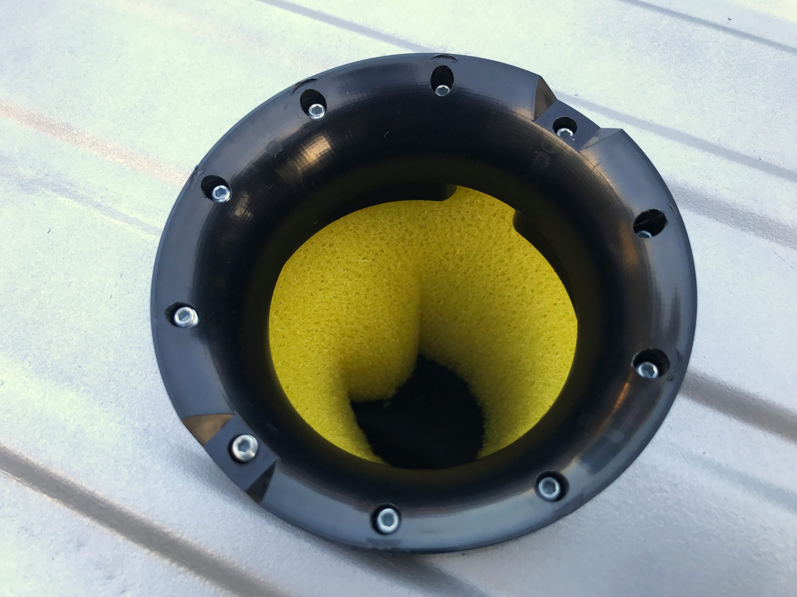
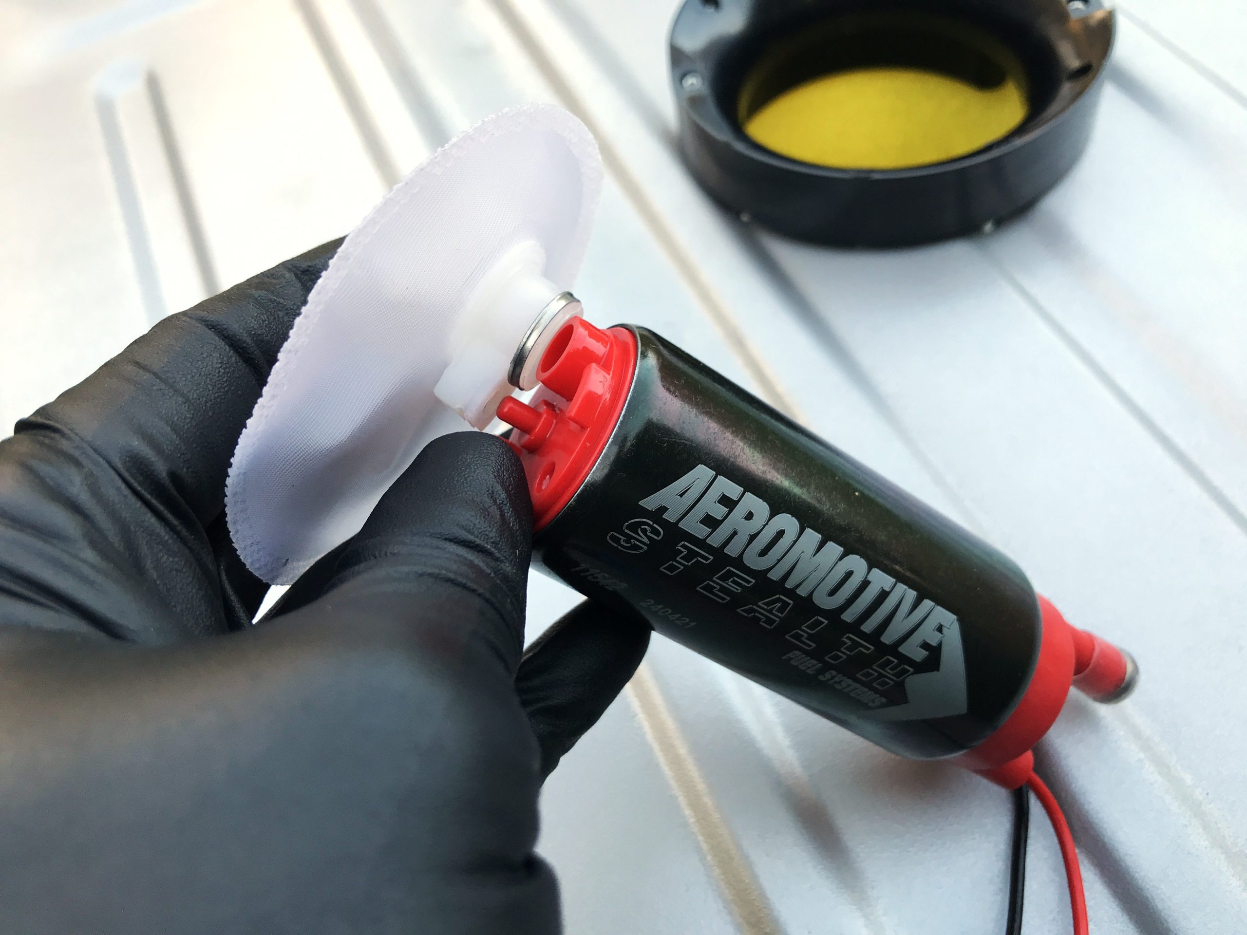
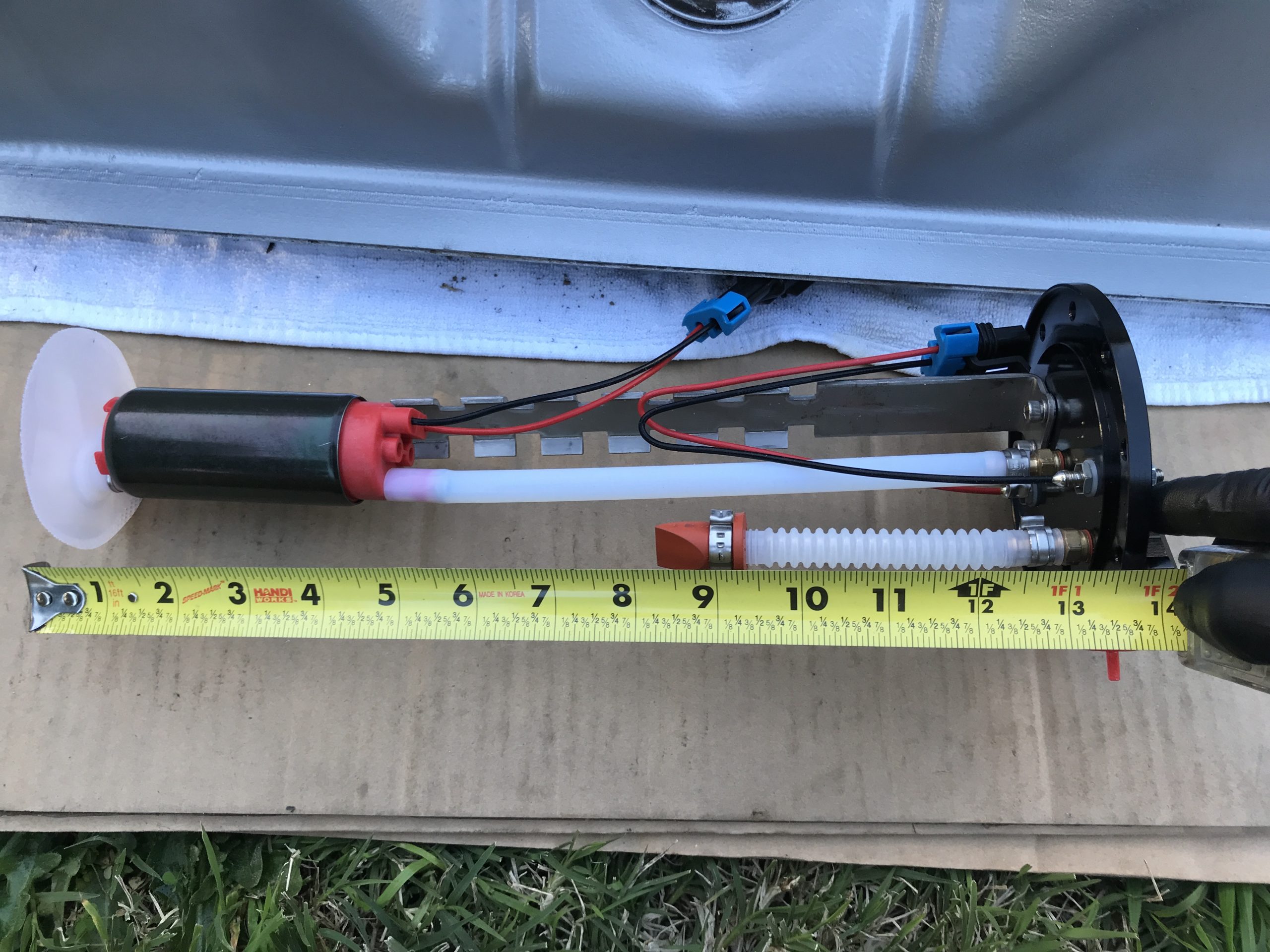
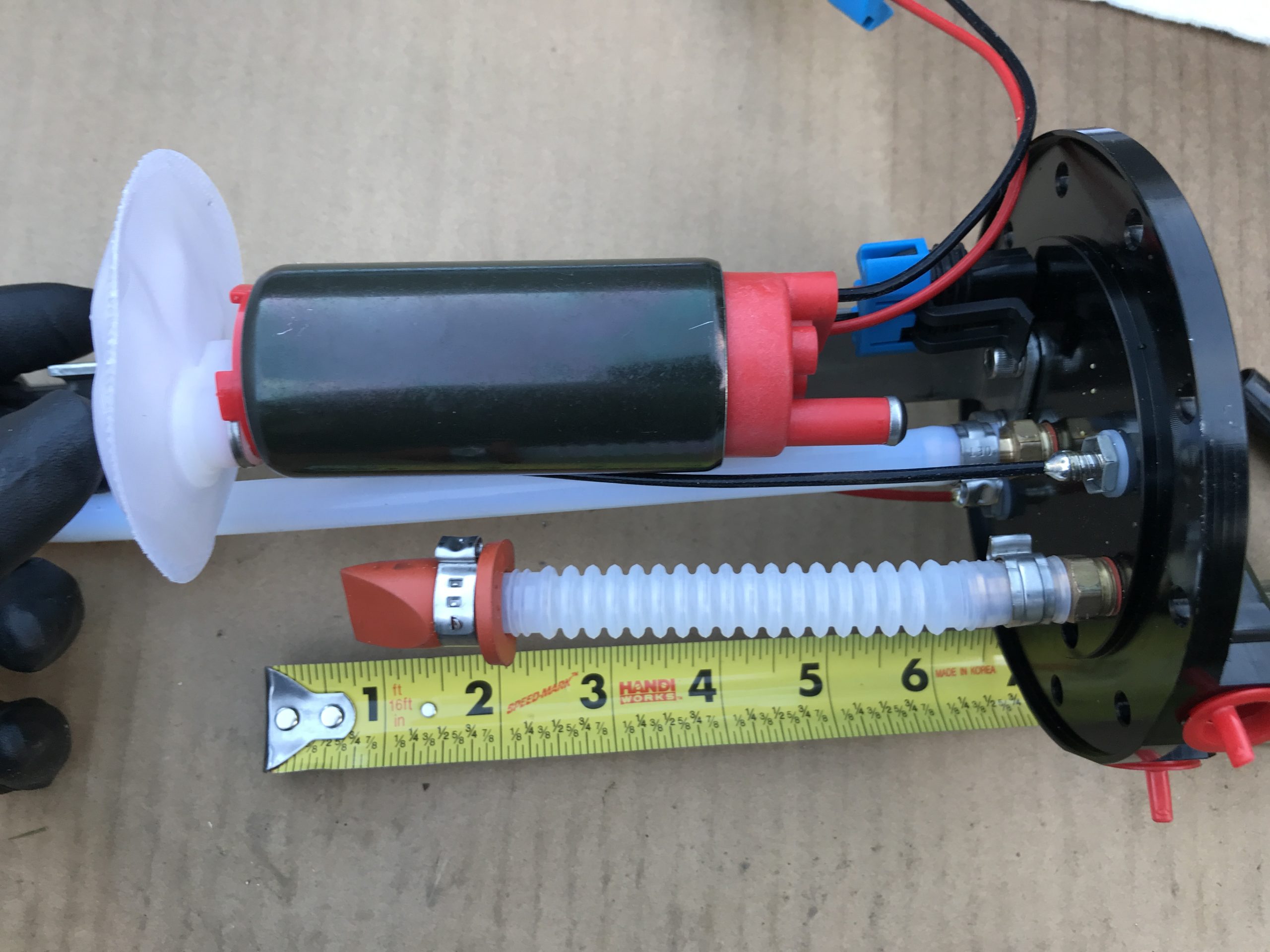
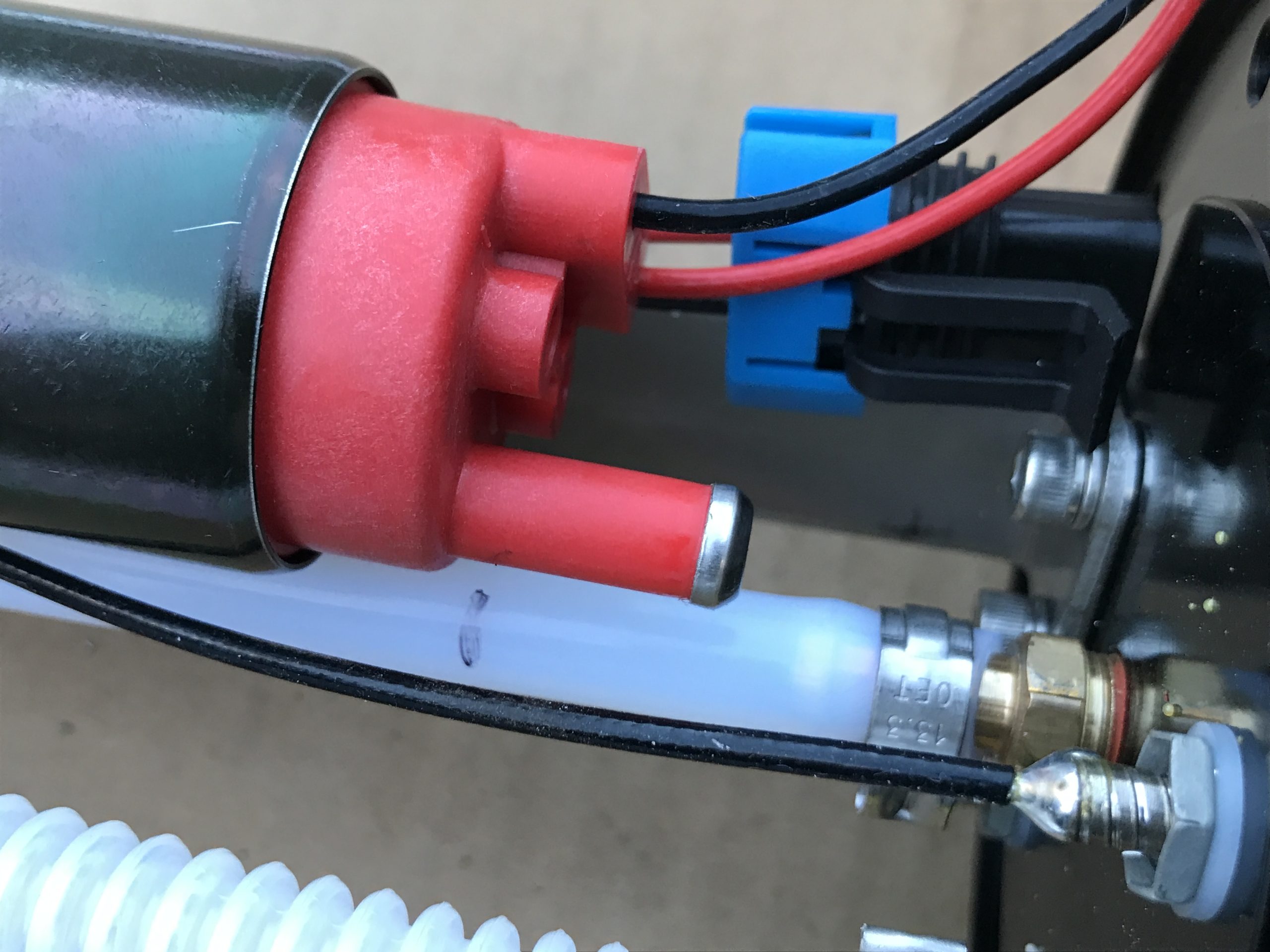
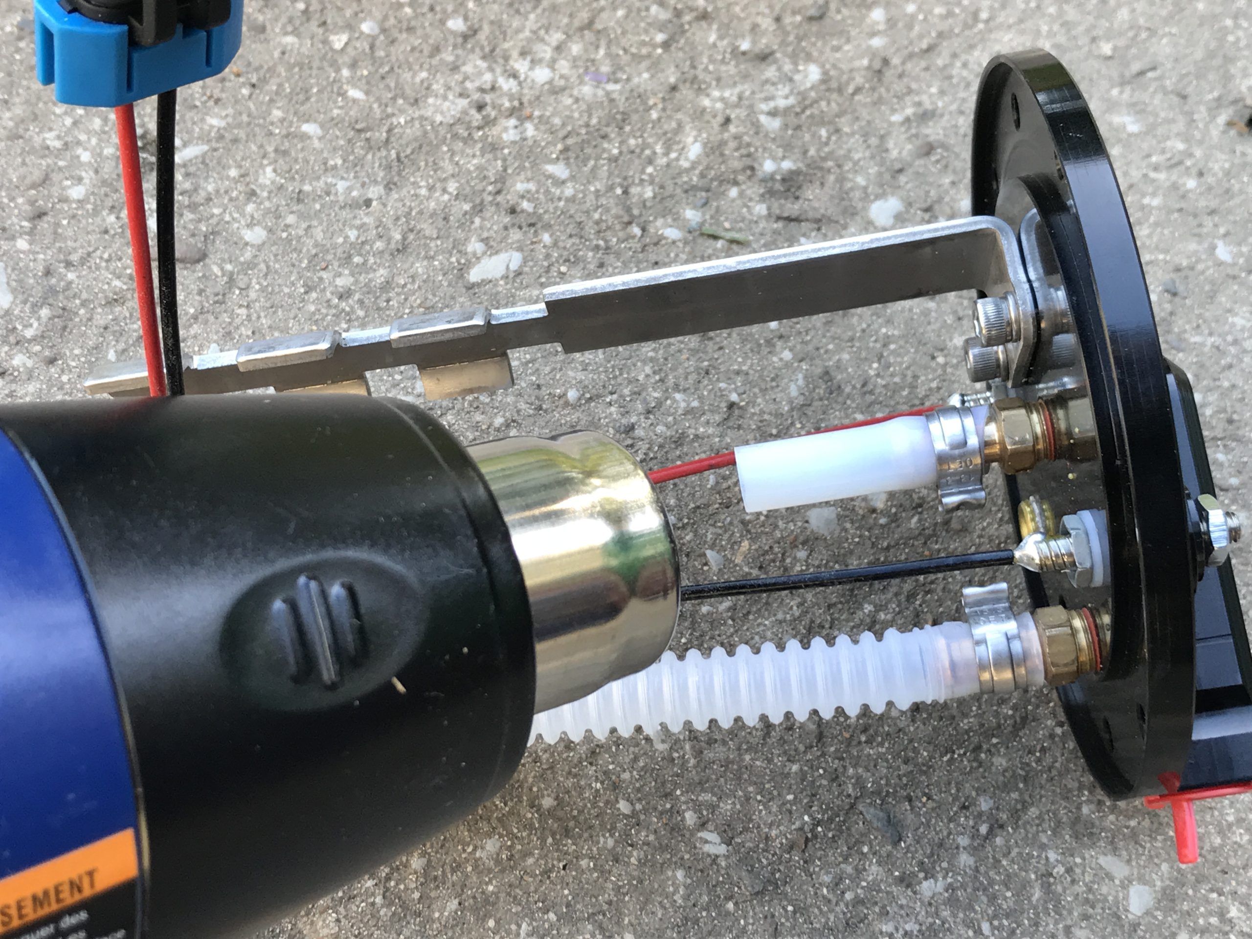
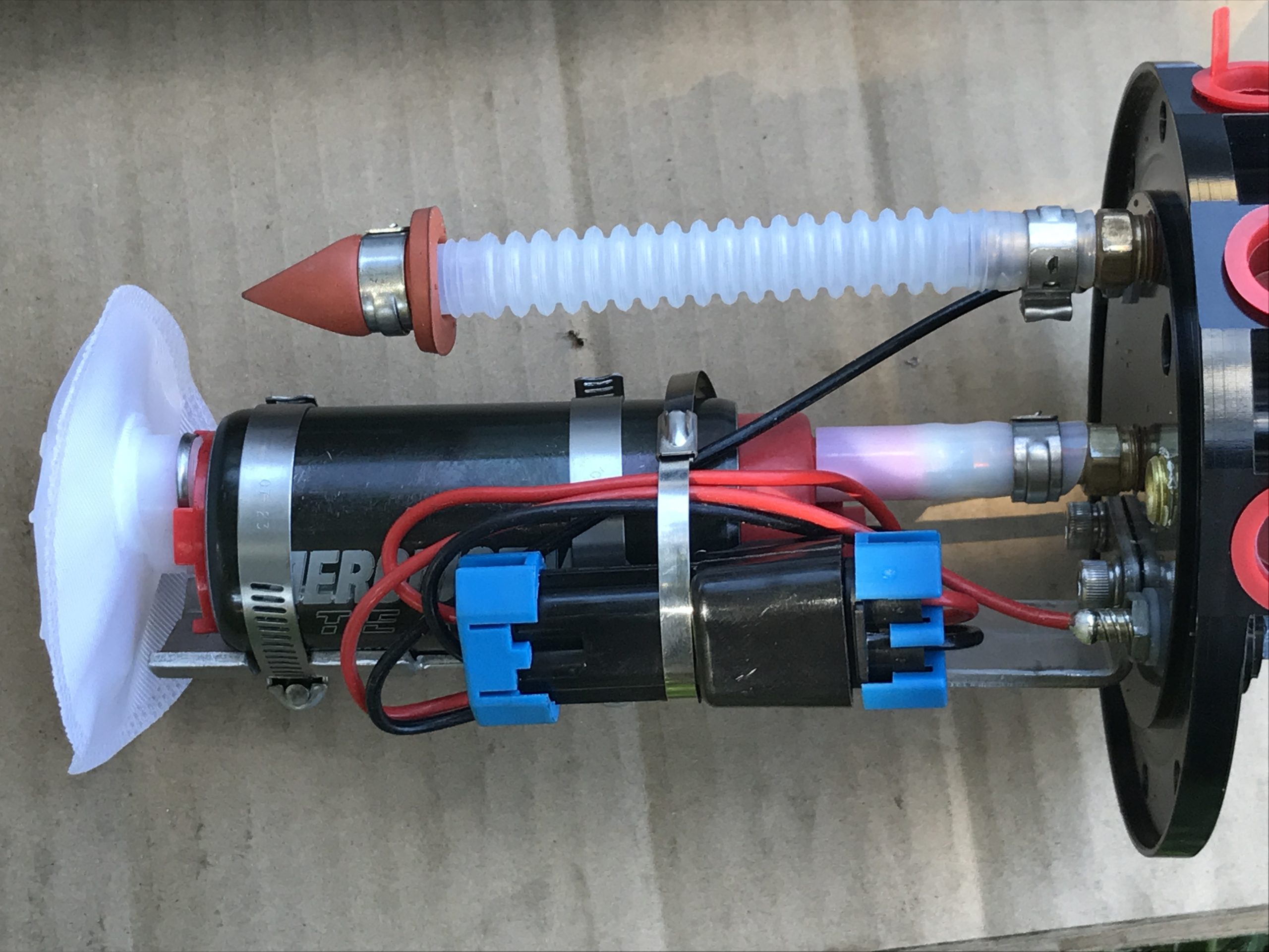
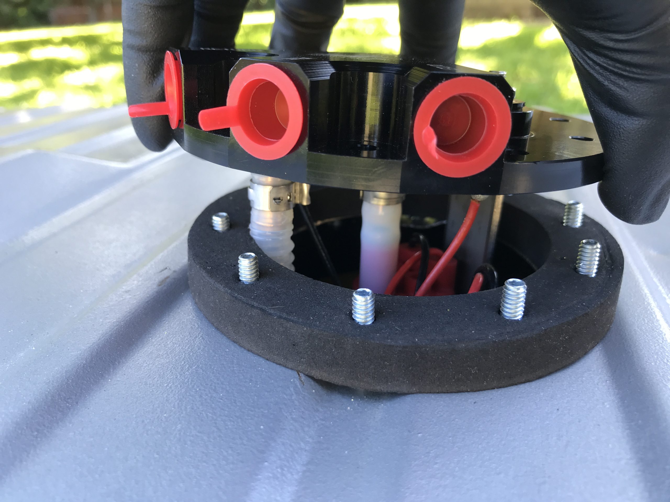
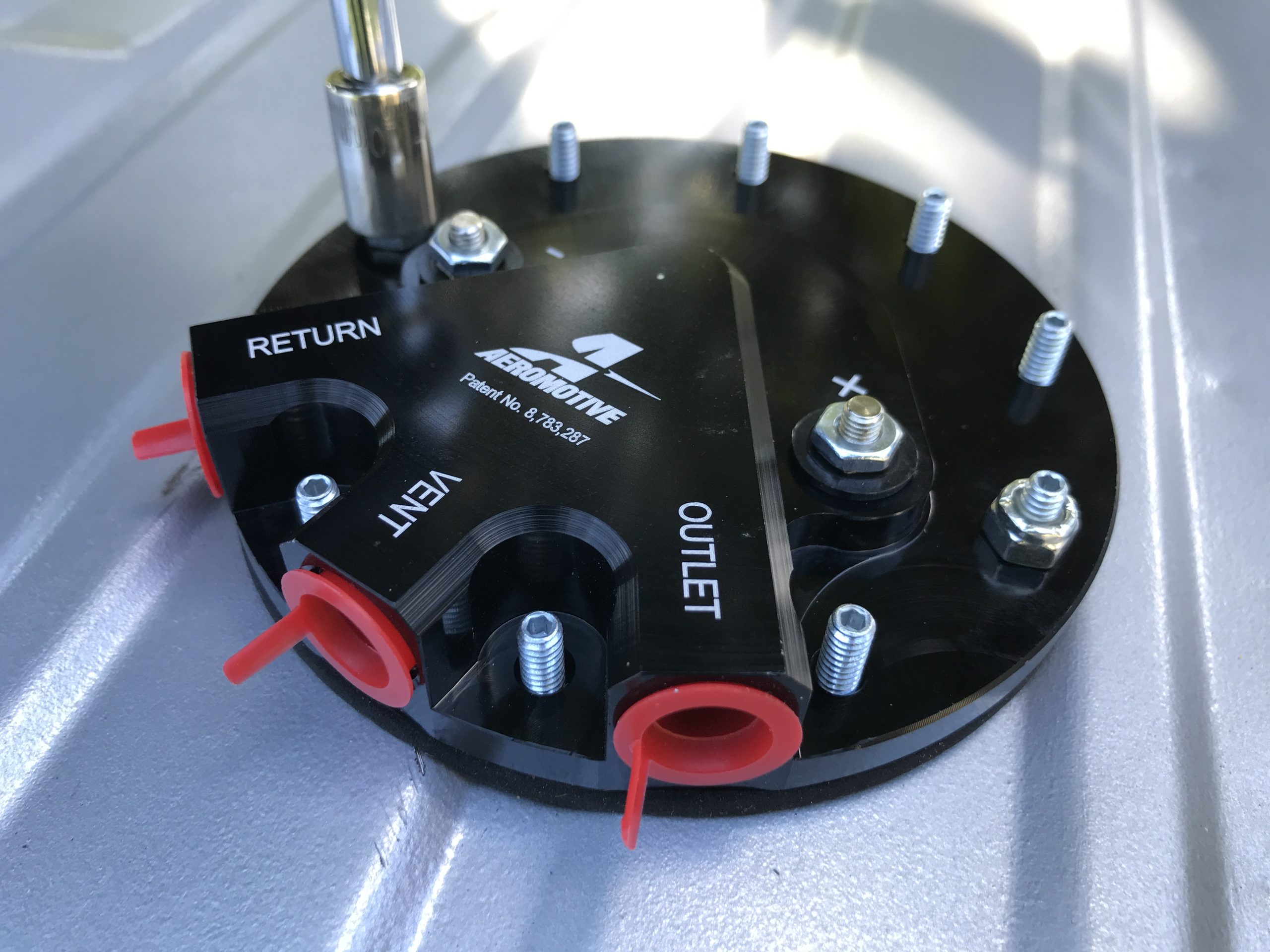
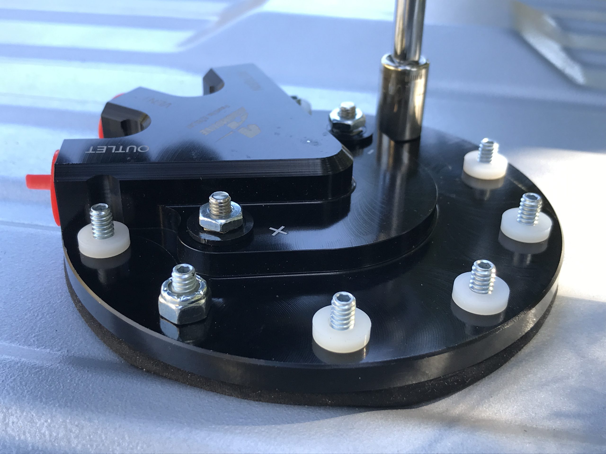
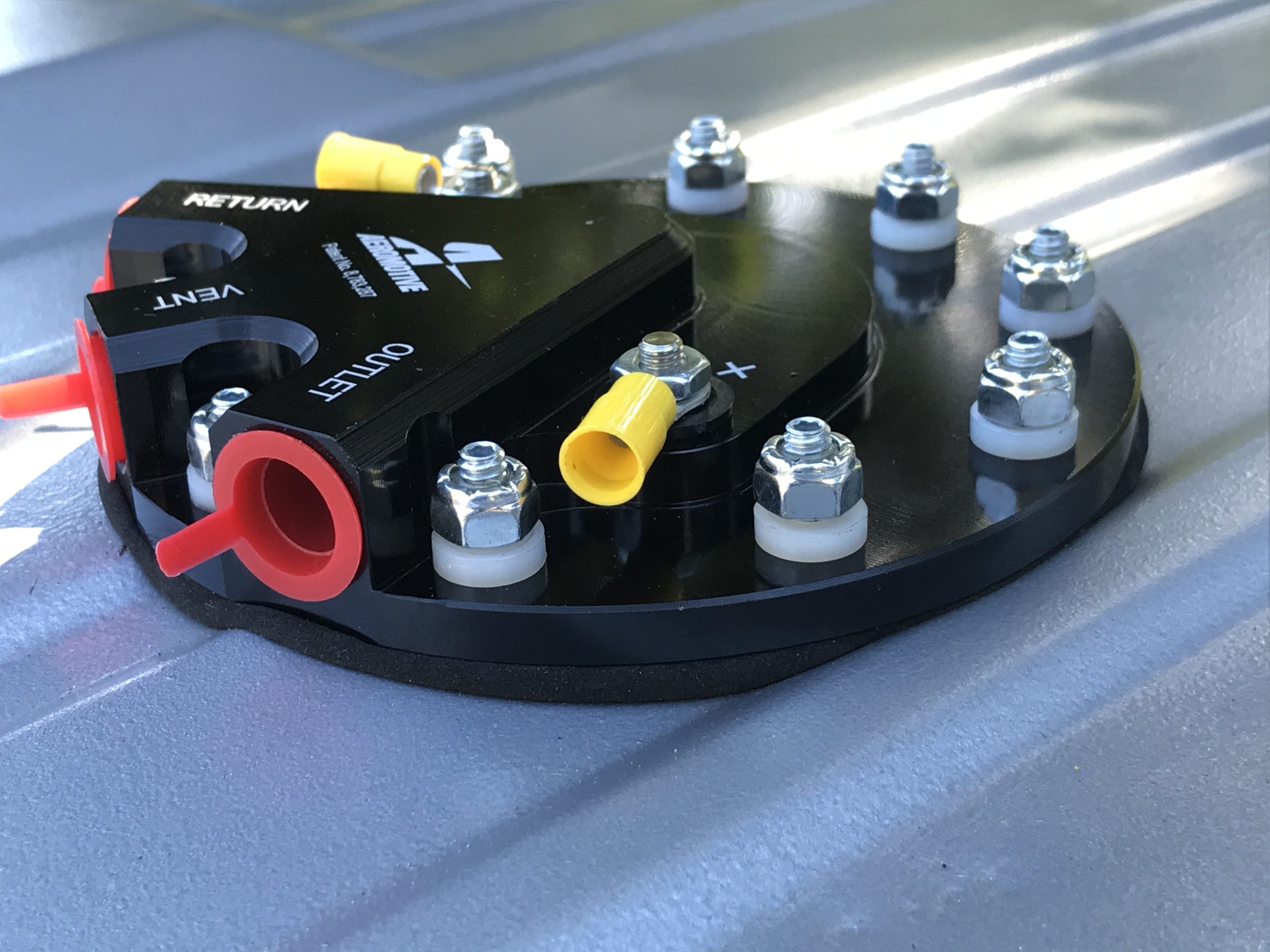
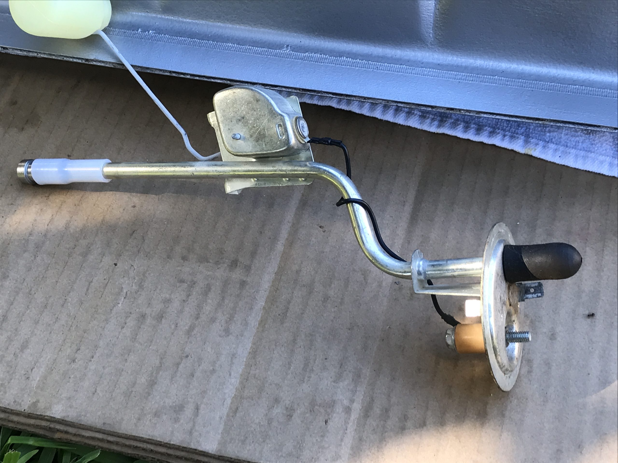
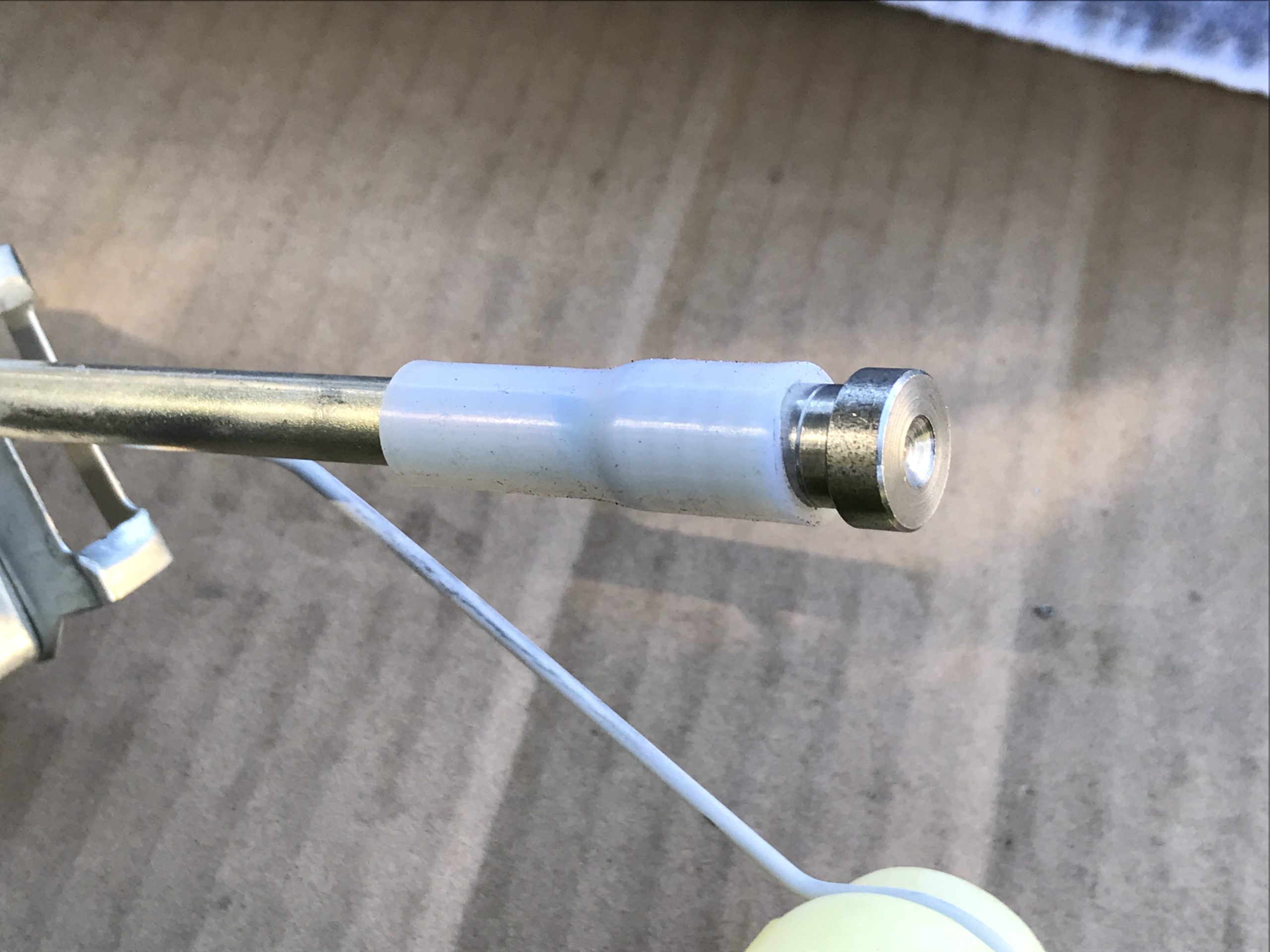
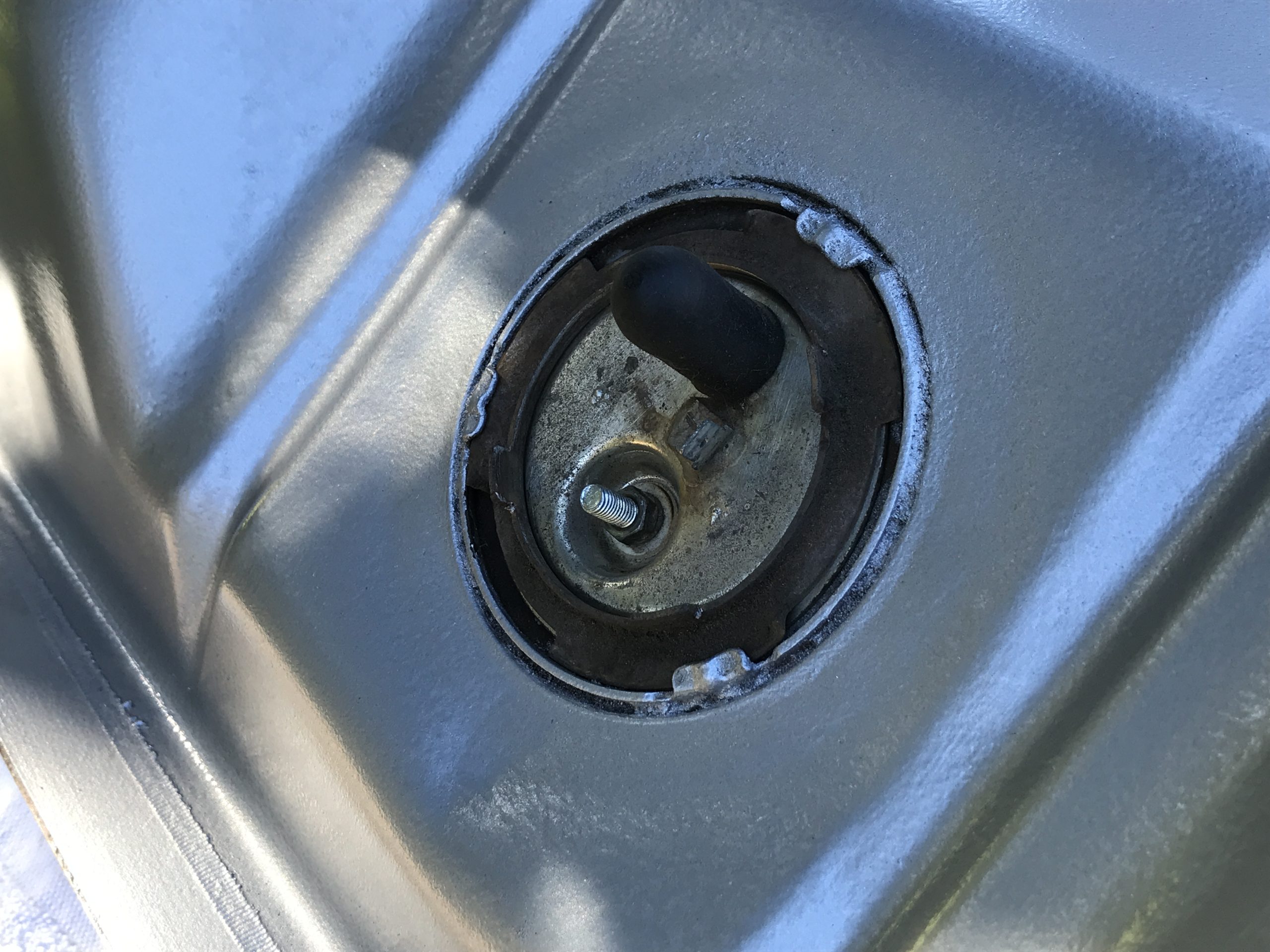
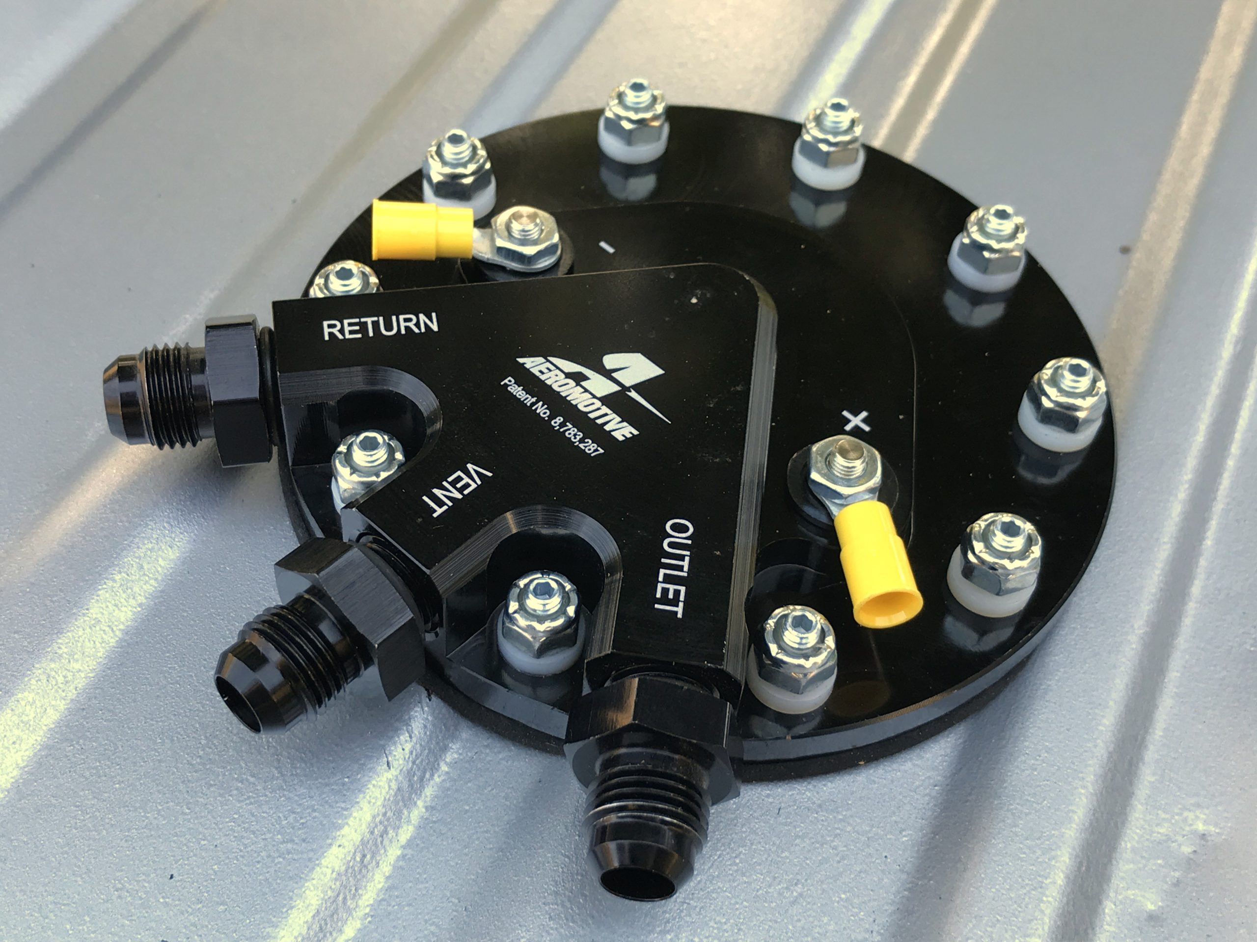
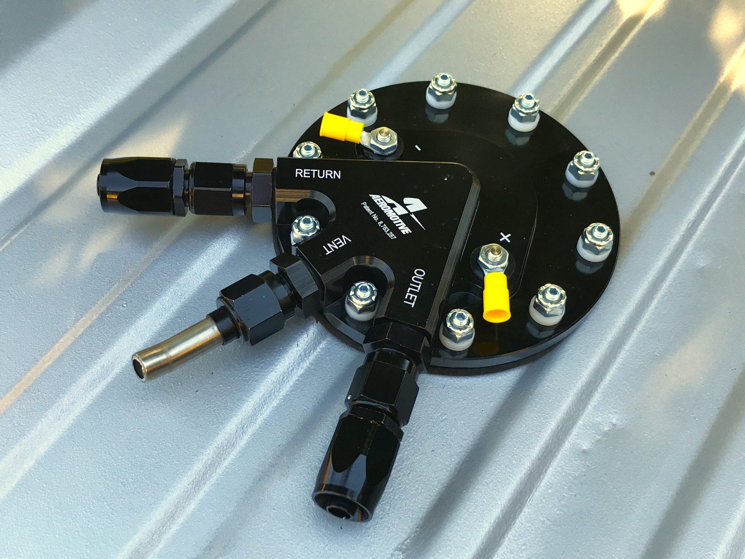
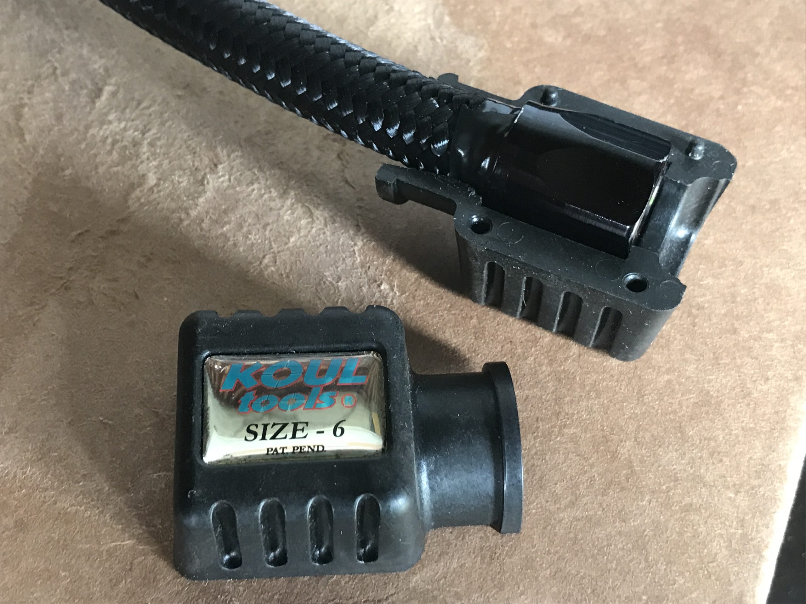
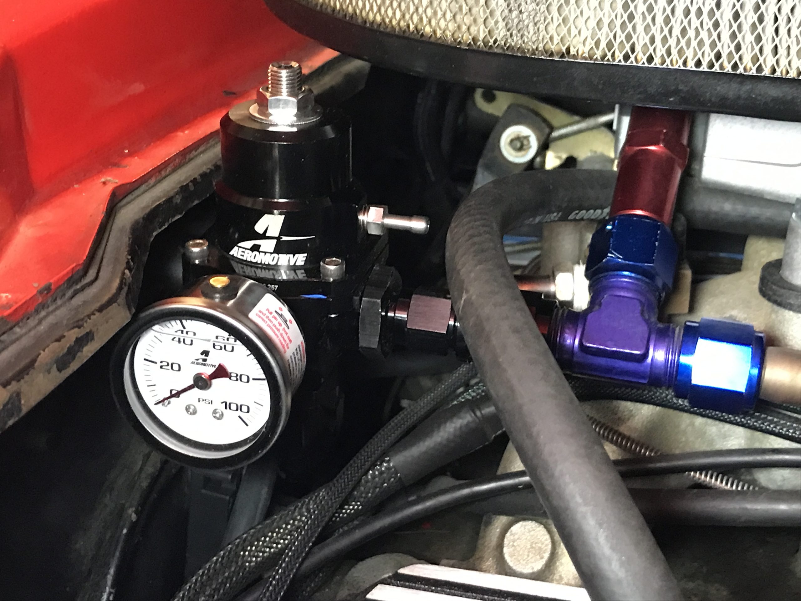
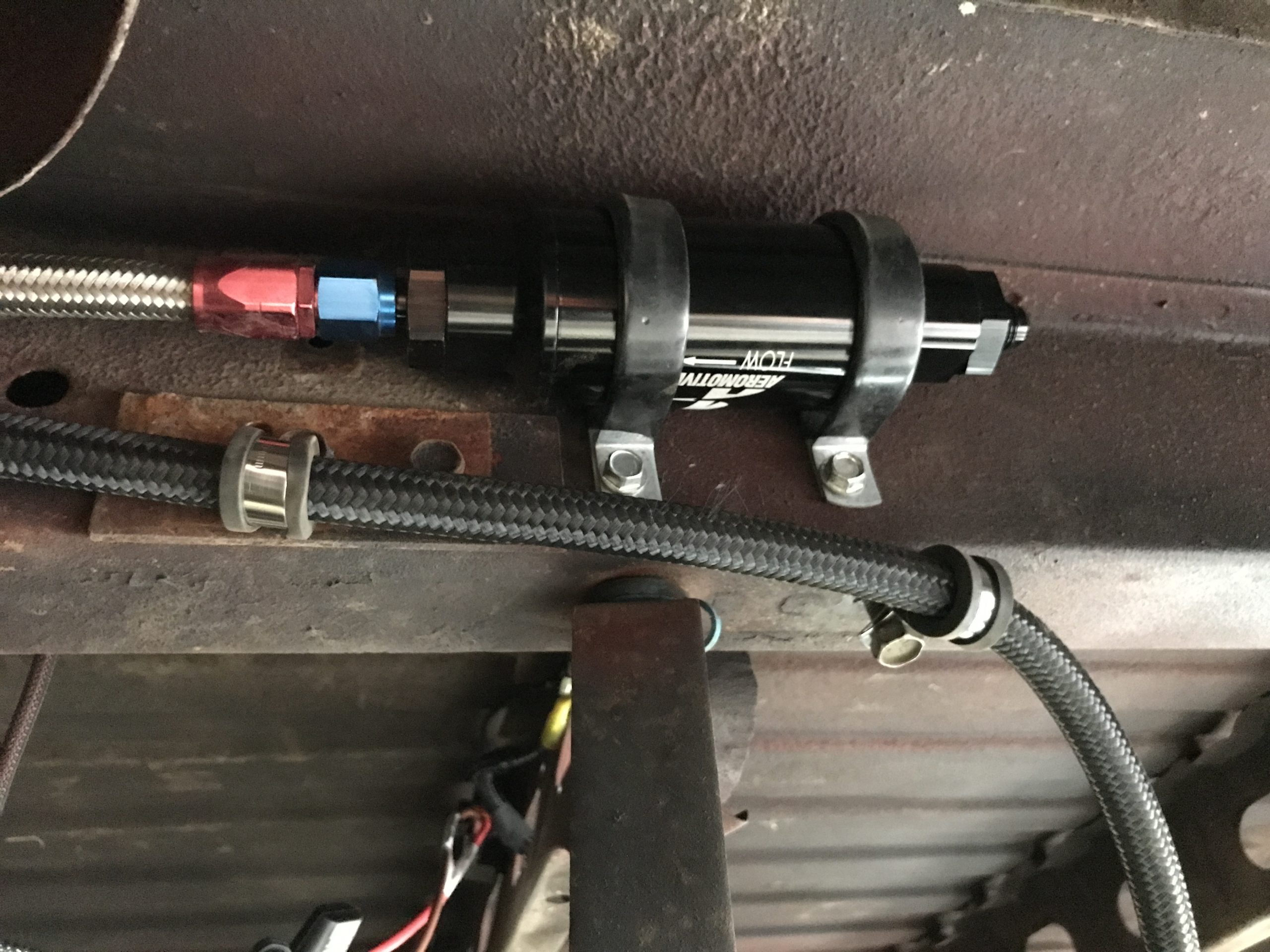
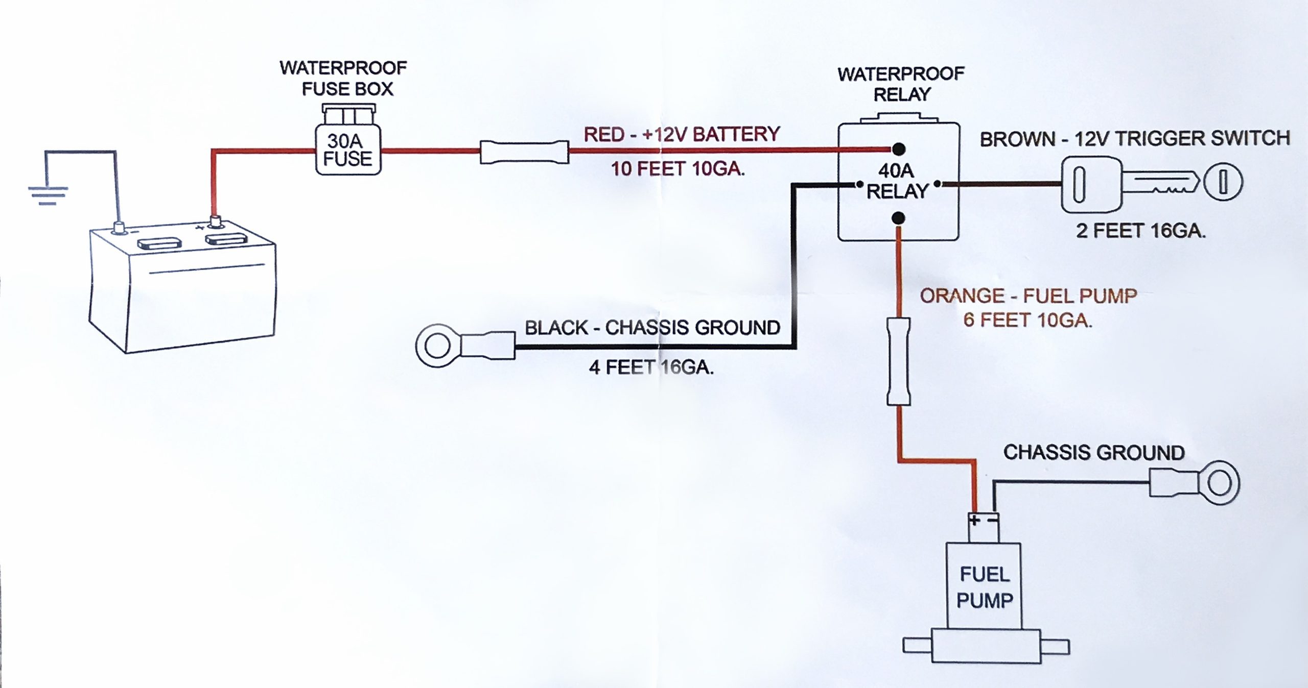
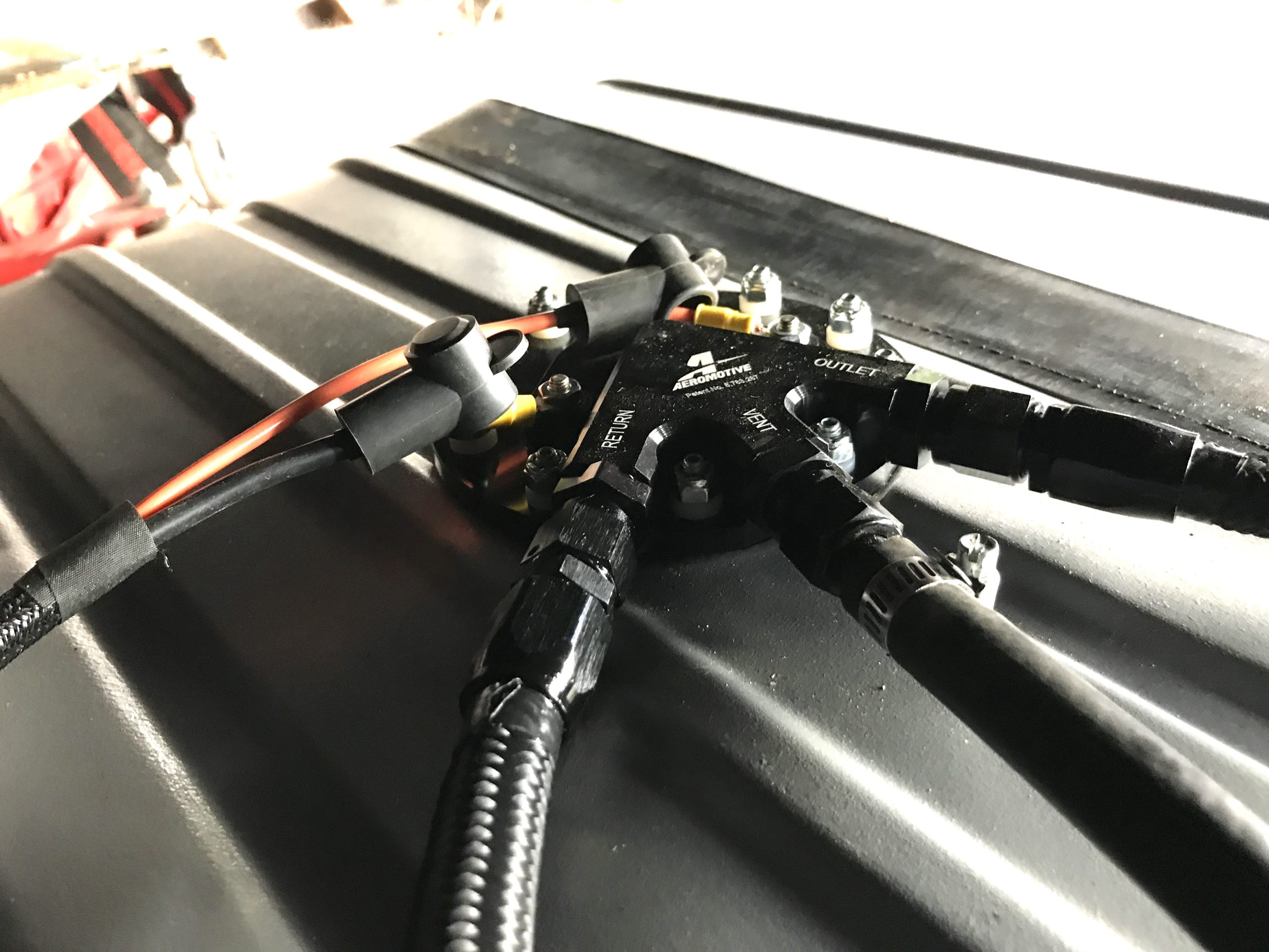
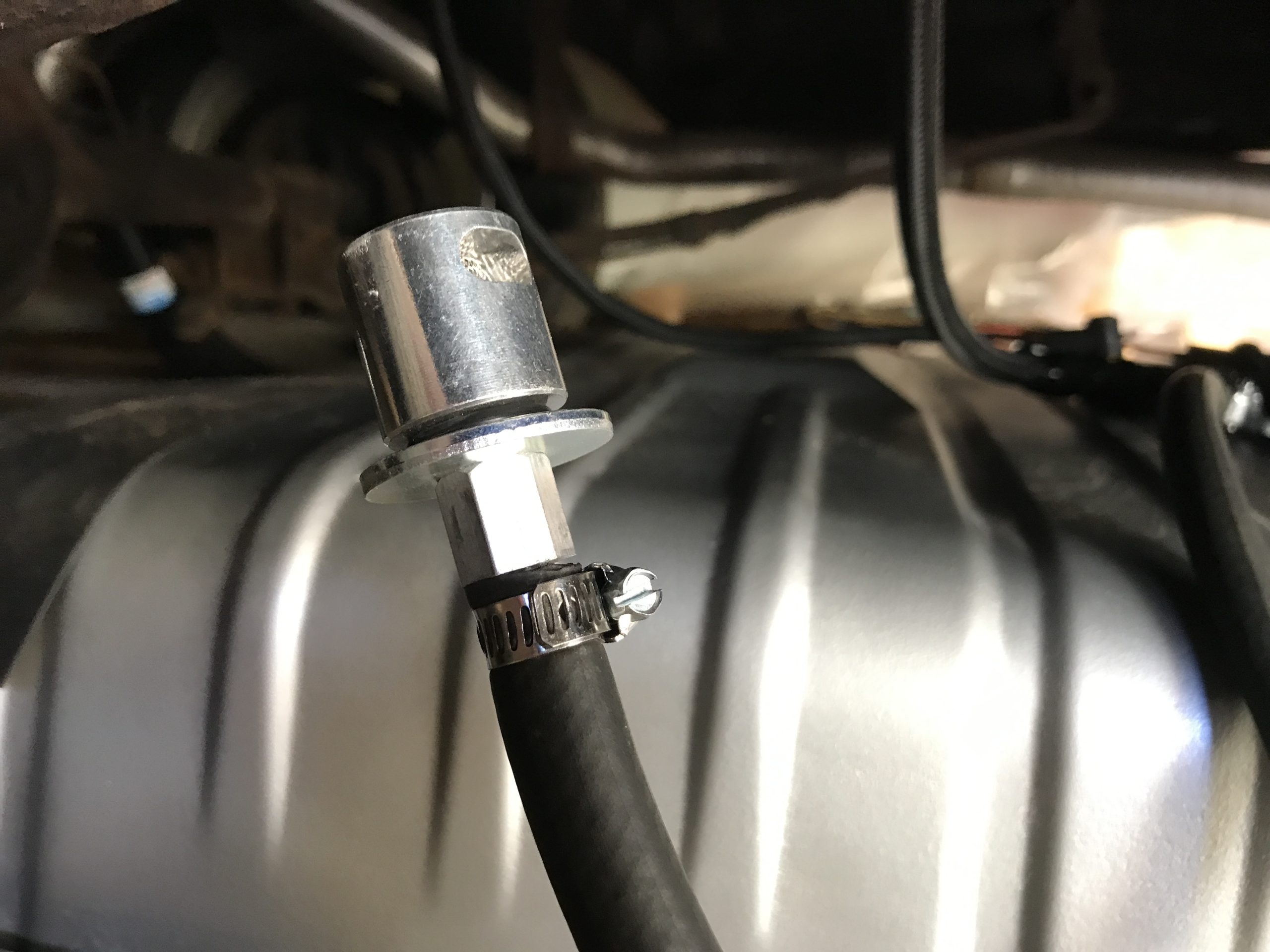
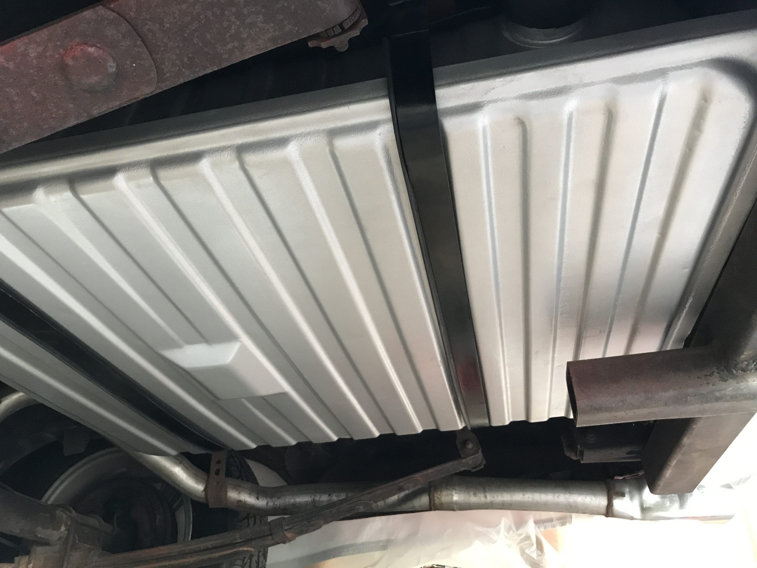
We’re going to skip over the details on dropping the fuel tank since every car is different, but before you remove anything, take a good look at the clearance on the top side of the tank. The Phantom fuel hat will stick up about two inches above the tank, so locate areas where that height might contact the bottom of the vehicle. We’re in luck with our project; our 1967 Ranchero has several inches of clearance between the tank and the bed floor. (Image/Christopher Campbell)Here’s our unsupported oddball tank. You might be scratching your head and wondering why there is a sump and a drain plug on the top of the tank. That’s because Ford’s cost cutting strategy for the fuel tank on 1966-71 Rancheros was to flip a Falcon tank upside down and move the inlet to the driver side quarter panel. Believe it or not, these single application tanks are reproduced. Ours is in near perfect condition inside, so we’re going to reuse it. (Image/Christopher Campbell)These are the major components that allow the Phantom 340 kit to adapt an in-tank EFI fuel pump on just about any automotive fuel tank. We’ll be using a standard single pump system with a return line and fuel pressure regulator, but Aeromotive also has a version with dual pumps for big horsepower and a version with a built-in fuel pressure regulator if you want to avoid running a return line. (Image/Christopher Campbell)Your current fuel tank has an insert that features a fuel line port and level sensor. The Phantom 340 billet hat will provide the new inlet, outlet, and vent, so we’ll show you how to plug up the factory port. (Image/Christopher Campbell)With 10 mounting holes to be drilled, this is how Aeromotive simplifies the install for the fuel hat. Once the main hole is cut, the plastic ring on the right will register into it and create a guide for the rest. (Image/Christopher Campbell)These small holes at the bottom of the fuel cup allow fuel to flow in and create a column around the fuel pump that will keep the inlet always submerged in fuel and the pump running cool. (Image/Christopher Campbell)We know where our tank contacts the chassis mounts, so now we zero-in on the pump mounting location by identifying the areas to avoid. For example, we need to stay away from the fuel level sending unit and float arm, so we laid it on top of the tank to visualize the approximate location. We also need to avoid areas where the fuel filler neck may protrude inside the fuel tank. (Image/Christopher Campbell)Our tank does not have any flat areas large enough to accommodate the Phantom 340 fuel hat, but this thick gasket will compress and form to ribs up to quarter inch deep. For extreme cases where the ribs are deeper or oddly shaped, Aeromotive recommends the use of a fuel resistant sealant such as, Dow Corning 730 fluorosilicone RTV. Do not use silicone gasket maker or sealant, as it is not fuel resistant. (Image/Christopher Campbell)Speaking of ribs, before any drilling done, flip the fuel pump retainer ring (C-shaped part with 10 threaded studs) upside down and use it as a guide to determine the fuel pump mounting location. Clock it to ensure that none of the holes on the bolt pattern would have to be drilled into the side walls of the ribs. Shown here is what we want to avoid. (Image/Christopher Campbell)This is what we want, all the studs will pass through flat portions of the tank, and it will be balanced across the ribs. Note that the fuel pump retainer ring will be on the inside of the fuel tank, so position it across the ribs that protrude into the tank. This also helps us align the stud locations. (Image/Christopher Campbell)Now that we have everything positioned and aligned, it’s time to drill a small pilot hole. This hole will determine the position of everything, so use a center punch to make sure the drill bit doesn’t walk, and the resulting pilot hole is exactly where you want it. (Image/Christopher Campbell)It’s hole saw time! You’ll need a 3.25 inch diameter hole saw that is made for cutting sheetmetal. You’ll also need a high torque drill, meaning a cordless probably won’t get the job done. This is overkill, but we don’t get the opportunity to use our vintage half inch drive Milwaukee drill very often, and it’s kind of fun. There’s no welding involved with this retrofit, so the heat and spark potential is very low. However, if you’re working with an original tank like us, we highly recommend having the tank professionally cleaned to remove any sources of combustible vapors—even if it has been sitting empty for an extended period. (Image/Christopher Campbell)Even the best hole saw will leave some sharp edges, so following behind with a curved file to knock down anything that might snag the Phantom 340 (or your hand) is highly recommended (Image/Christopher Campbell)Place the included installation ring over the 3-1/4 inch hole so the raised register drops into it and rotate it until the bolt pattern is in the predetermined alignment with the tank ribs. Use the included #2 drill bit and drill one of the bolt pattern holes and place one of the included 10-24 x 2-1/2 inch screws in the hole to help hold the index ring. Drill a second hole, directly across (180 degrees) from the first, and place the second 10-24 x 2-1/2 inch screw in the hole. Then drill the remaining eight holes (Image/Christopher Campbell)Using the fuel pump retainer ring, align the studs with the newly drilled holes and check for proper fit. Don’t feel bad if one or two of your holes need a little filing or another pass of the drill bit for the ring to slide in easily, a couple of ours did. This won’t affect the final outcome. (Image/Christopher Campbell)We’re done with the tank modification! Now it’s time to carefully measure the depth of the tank to determine how much to trim the Phantom 340 insert. Our is 6.5 inches, on the nose. This is also a good point to thoroughly vacuum out the interior of the tank to remove any metal shavings. (Image/Christopher Campbell)Measure the foam baffle assembly from the bottom (black rubber part) up and mark the foam one inch longer than the determined tank depth. Our tank is 6.5 inches deep, so we marked the foam baffle assembly at 7.5 inches long. (Image/Christopher Campbell)You can use your favorite method of cutting, but we recommend a good set of scissors.(Image/Christopher Campbell)Now it’s time to install the fuel pump retainer ring into the fuel tank from the inside. The C-shape allows the ring to be inserted through the smaller hole, to the inside of the tank. (Image/Christopher Campbell)From there, the studs can be pushed up through the holes. (Image/Christopher Campbell)To protect the Phantom insert during installation, place the installation ring over the retaining ring studs. With the foam baffle fully inserted into the rubber cup, compress the baffle assembly, and insert it through the installation ring into the tank being careful not to cut the assembly or your hands on the tank edge. (Image/Christopher Campbell)Once the baffle assembly is in the tank, manipulate it until it’s centered within the opening, but be cautious to not tear it. The final position should look like this. (Image/Christopher Campbell)It’s time to prep the hanger assembly, so the fuel pump strainer (pre-filter) must be clipped onto the fuel pump to ensure accurate measurement. (Image/Christopher Campbell)The Phantom 340 can accommodate tank depths from 6 to 11 inches. This is the full-length hanger assembly as shipped. (Image/Christopher Campbell)Our tank is at the very bottom range, so this is where we need the pump to be positioned. (Image/Christopher Campbell)Here’ s a close-up of how close the pump and the fuel hat inlet will be. Make sure to position the fuel pump on the fuel pump hanger assembly such that from the bottom of the outlet cap to the bottom of the fuel pump strainer is equal to the fuel tank depth. (Image/Christopher Campbell)Using a rotary cutting wheel or metal saw, cut the bracket to the appropriate length. We want to remove enough at the bottom to ensure that the end of the bracket will not contact the fuel pump strainer, but ensure the pump is fully braced. Remember, take the time to measure twice and cut once! (Image/Christopher Campbell)To ease installation of the Aeromotive 340 pump into the hose, we highly recommend warming it up slightly with a heat gun. We don’t want it soft, just warm enough to be pliable and allow some expansion for the pump outlet. (Image/Christopher Campbell)Once the pump is inserted into the hose, use the two large hose clamps to attach the pump to the pump hanger bracket and tighten. Plug the electrical connector into the pump and tuck the wire out of the way. (Image/Christopher Campbell) Now install the gasket onto the threaded studs on the fuel pump retaining ring. If the top of the tank is corrugated or has ribs on the desired mounting surface, the included gasket will compress and form to the ribs up to a quarter inch deep. In extreme cases where the ribs are deeper than 3/4 inch, or oddly shaped, the use a fuel resistant sealant such as Dow Corning 730 fluorosilicone RTV to ensure a good seal. (Image/Christopher Campbell)With the fuel pump hanger fully assembled and the gasket in place, ease the pump hanger assembly into the baffle assembly inside the fuel tank. Rotate the billet fuel pump hanger assembly to orient the fuel line and vent connections in the direction you want the fuel hoses to run and drop the hanger onto the retaining ring studs. Take extra care to ensure that the fuel pump wires are fully inside of the tank and will not be pinched in between the pump assembly and the fuel tank. (Image/Christopher Campbell)Press down firmly on the top of the pump assembly to compress the gasket. Start two of the 10-24 lock nuts on a pair of studs 180 degrees apart. Tighten these two nuts until the remaining studs are approximately a quarter inch exposed. (Image/Christopher Campbell)Place one of the #10 white nylon sealing washers on each of the other eight studs followed by a 10-24 locking nut and lightly tighten them. Remove the first two lock nuts used to help compress the gasket and place a #10 white nylon sealing washers on each of these two studs, followed by reinstalling the 10-24 locking nut. (Image/Christopher Campbell)With all 10 studs now having a #10 white nylon sealing washer and a locking nut, slowly tighten using a crisscross pattern until the gasket forms to the tank surface. (Image/Christopher Campbell)While we’ll still be using the fuel level sender, the fuel line won’t be connected, so we’re permanently capping it. (Image/Christopher Campbell)Using a small piece of the fuel pump hose, we heated it and slid it over the fuel line and plugged the other end with a 3/8 inch stainless steel barb. (Image/Christopher Campbell)With the fuel sending unit reinstalled into the tank, we pushed a vacuum cap over the original fuel line to keep dirt out. (Image/Christopher Campbell)We’re done with the tank itself, but before it can go back in place, we need to address our new fuel lines and vent. Each port on the fuel hat uses a -6 AN O-ring adapter fitting. (Image/Christopher Campbell)We try to use straight hose ends whenever possible, and thankfully we have enough room for it to work. If your install needs some curves, these -6 Aeromotive fittings are available in multiple configurations. (Image/Christopher Campbell) Aeromotive has created an easy to search library of fuel system diagrams specifically for the Phantom 340. We’re running an old throttle body style EFI system that uses a single inlet, so this is the diagram the most closely matches what we want to build. It’s also an ideal way to figure out the list of fittings and hoses end you’ll need. You can view the entire Phantom 340 diagram library to find your system here.(Image/Aeromotive)We’re not going to bore you with routing for the return line since every install will be different. However, we will advise you to pick up one of these Koul Tool kits to make your custom hoses with the Summit Racing Braided Nylon Hose if you don’t already have one. They install hose ends in seconds and create a perfect seal every time. (Image/Christopher Campbell)It’s always a best practice to keep your fuel pressure regulator close to the injectors to minimize pressure fluctuations. Our EFI throttle body uses a carburetor style fuel log that features a fitting at the rear that will allow us to mount the Aeromotive fuel pressure regulator directly to the fuel log and simplify the fuel lines. If you have this type of throttle body, Aeromotive has an excellent fuel log (PN AEI-14201) that will allow you do the same type of install. All we need from here is a return line from the bottom of the regulator to the fuel tank. (Image/Christopher Campbell)A good EFI fuel system should have a filter both before and after the pump. Aeromotive has several reusable 10-micron filters to choose from as well as matching mounting brackets. The best practice for these filters is to keep them near the tank and easily accessible for cleaning. (Image/Christopher Campbell)Before your new Phantom 340 is ready to run, you’ll need a fuel pump relay supply power. Summit Racing has many relay kits to choose from, including a kit from Aeromotive. Whatever route you choose, make sure the wiring is large enough. Aeromotive recommends a 10 gauge power wire to the battery and a 10 gauge ground wire for the pump. (Image/Aeromotive)If you have a good weathertight relay, it doesn’t really matter where you decide to mount it. Ours is going above the fuel tank on one of tank mounts, which will keep it close to the pump. The 10 gauge power line will go directly to the battery and all grounds will go to the chassis. (Image/Christopher Campbell)We’re plumbed and wired! Though they don’t supply the relay or wiring, Aeromotive is kind enough to include these nice boots that help protect the pump terminals. (Image/Christopher Campbell)You may have noticed in the last pic that the vent line was just a standard 3/8 inch fuel line. That’s because we don’t need the braided line just to route our vent. We’re using a Summit Racing remote rollover vent valve that we’ll be running alongside the filler neck above the tank. (Image/Christopher Campbell)And there we have it; the factory tank is back in place and none of the modifications are easily visible! To test the system, we’ll pour in just enough fuel to pressurize the system and cycle it a few times to check for leaks and allow us to set the pressure on the Aeromotive regulator. Make sure you let the system sit pressurized for several minutes while you inspect, small leaks can take a few minutes to appear. (Image/Christopher Campbell)
Christopher Campbell has been heavily involved in the automotive world since he began building his first car, a 1967 Ford Ranchero, with his dad at the age of 14. That started a lifelong passion with custom hot rods and muscle cars. After graduating from Cal State Long Beach, he went to work for HOT ROD magazine as Associate Editor. From there he became Technical Editor at Popular Hot Rodding magazine. Currently he creates freelance content for OnAllCylinders as well as many diverse enthusiast magazine titles such as HOT ROD, Muscle Mustangs and Fast Fords, Mopar Muscle, Super Chevy, Mustang Monthly, and 8-Lug.


Comments