But whether it is an LS, Gen. V LT, Coyote, or Hellcat, these engines have a serious appetite for fuel. Feeding one requires a fuel delivery system than can provide the proper fuel volume and pressure.
Our project vehicle, a 1971 Buick GS convertible, has a Gen. V LT1 crate motor with a D1SC Procharger supercharger kit. Our horsepower goal is around 800 horsepower with an upgraded camshaft and the Procharger running six PSI of boost.
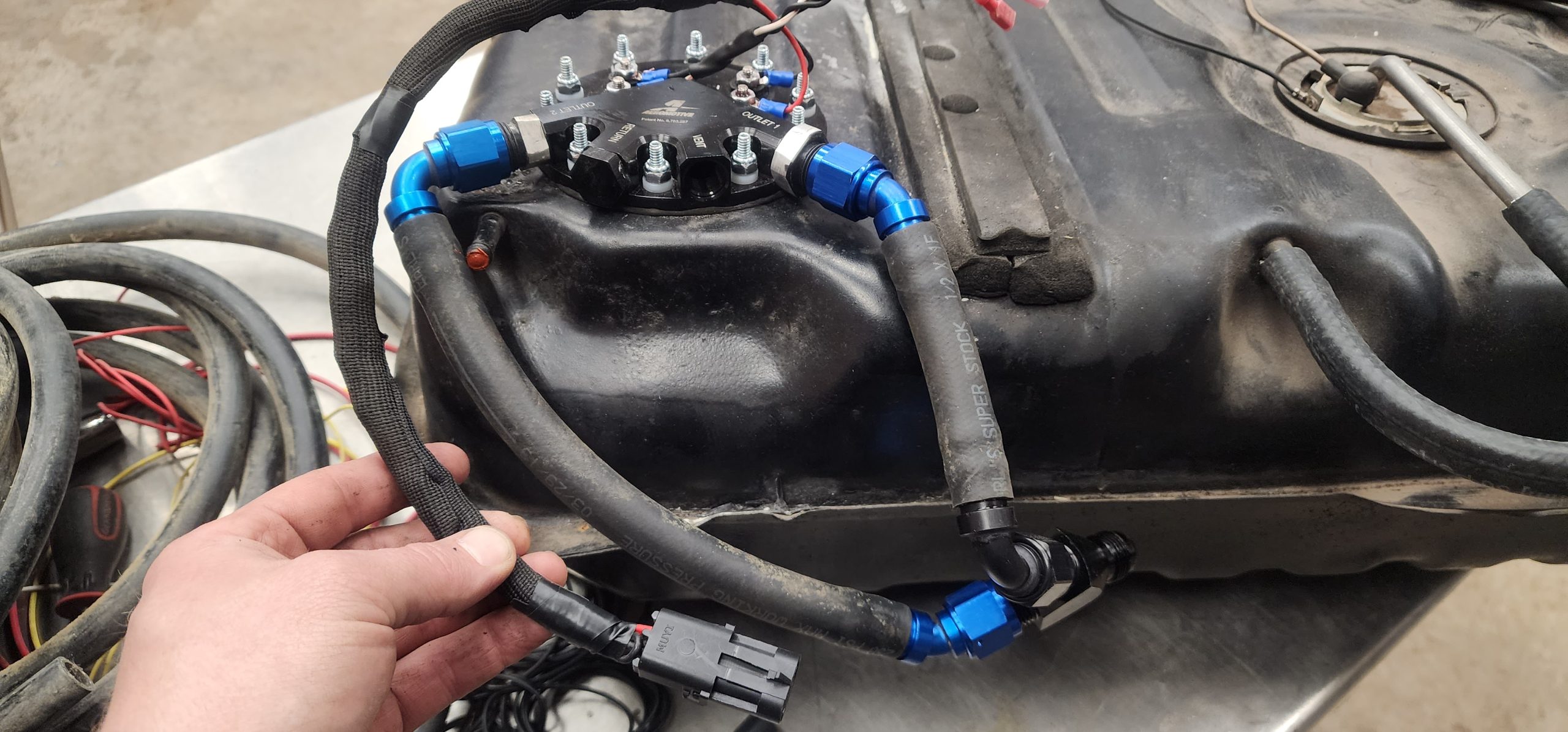
Enter the Aeromotive Dual Phantom In-Tank Fuel Module. It uses two Stealth 340 LPH fuel pumps and can handle engines rated at 2,000 horsepower naturally aspirated and 1,400 horsepower with EFI and boost. That will work nicely for our GS.
We will use the Dual Phantom system with an Aeromotive Fuel Pump Speed Controller (FPSC) that matches the pumps’ duty cycle to engine RPM via a pulse width modulation (PWM) signal. At low demand, the FPSC slows the fuel pump down, reducing the chance of suction side cavitation and vapor lock. When demand increases, the FPSC returns the fuel pump to 100% duty cycle for maximum flow.
For our GS, one pump will feed the LT1’s main fuel system. The second pump will feed fuel to a second set of injectors in the intake manifold once we get over the 750 horsepower mark, which is the limit of the factory direct-injection injectors.
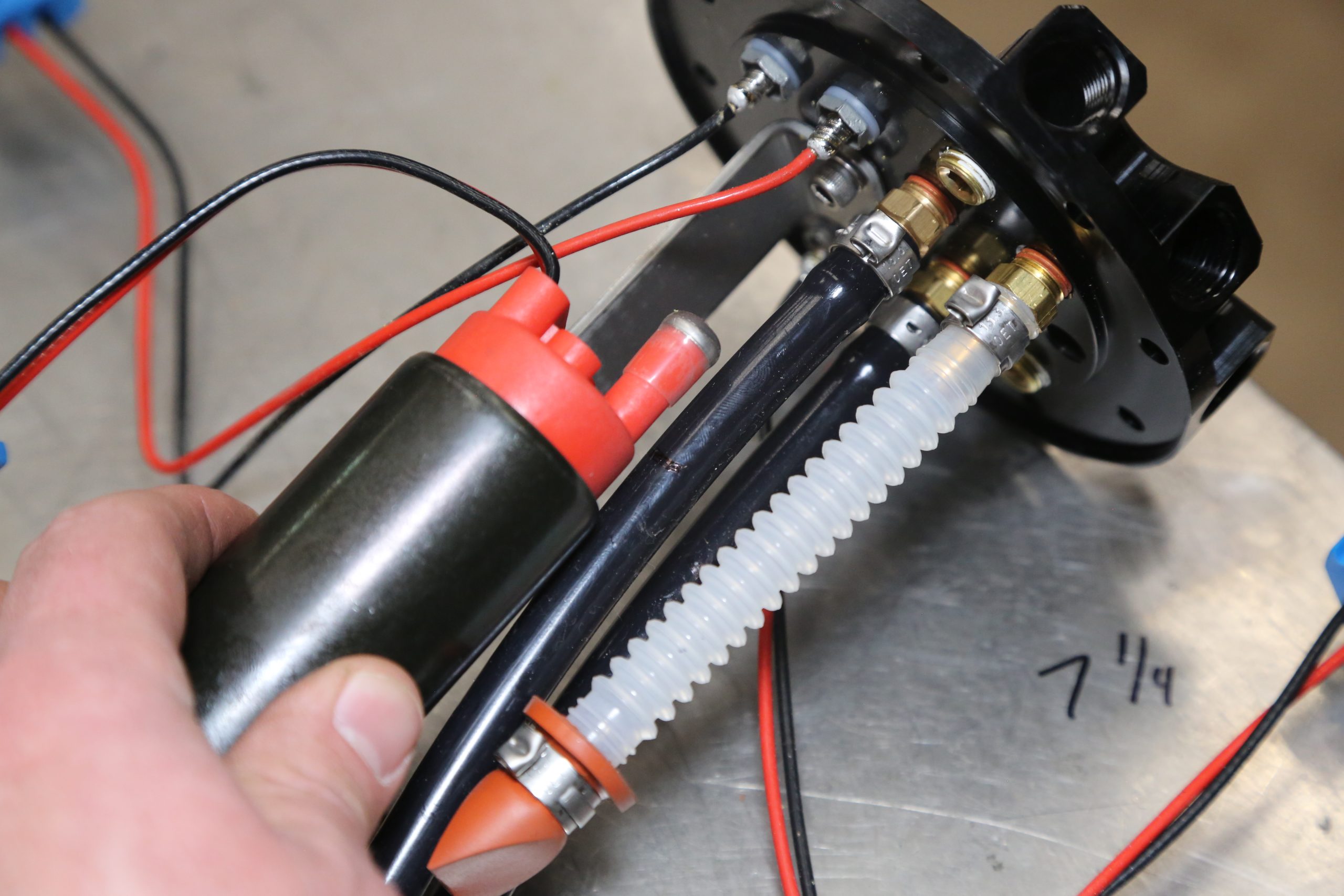
If you use a returnless fuel system like we are, the FPSC controller can cause issues. When the controlled pump suddenly shuts down, it can actually spin backwards as there is no return line to bleed off the pressure. To keep this from happening, we drilled a 1/32 inch hole in each of the two plugs in the pump pressure port on the module hat. These holes bleed off the pressure should the pump suddenly shut down.
How to Install an Aeromotive Dual Phantom In-Tank Pump
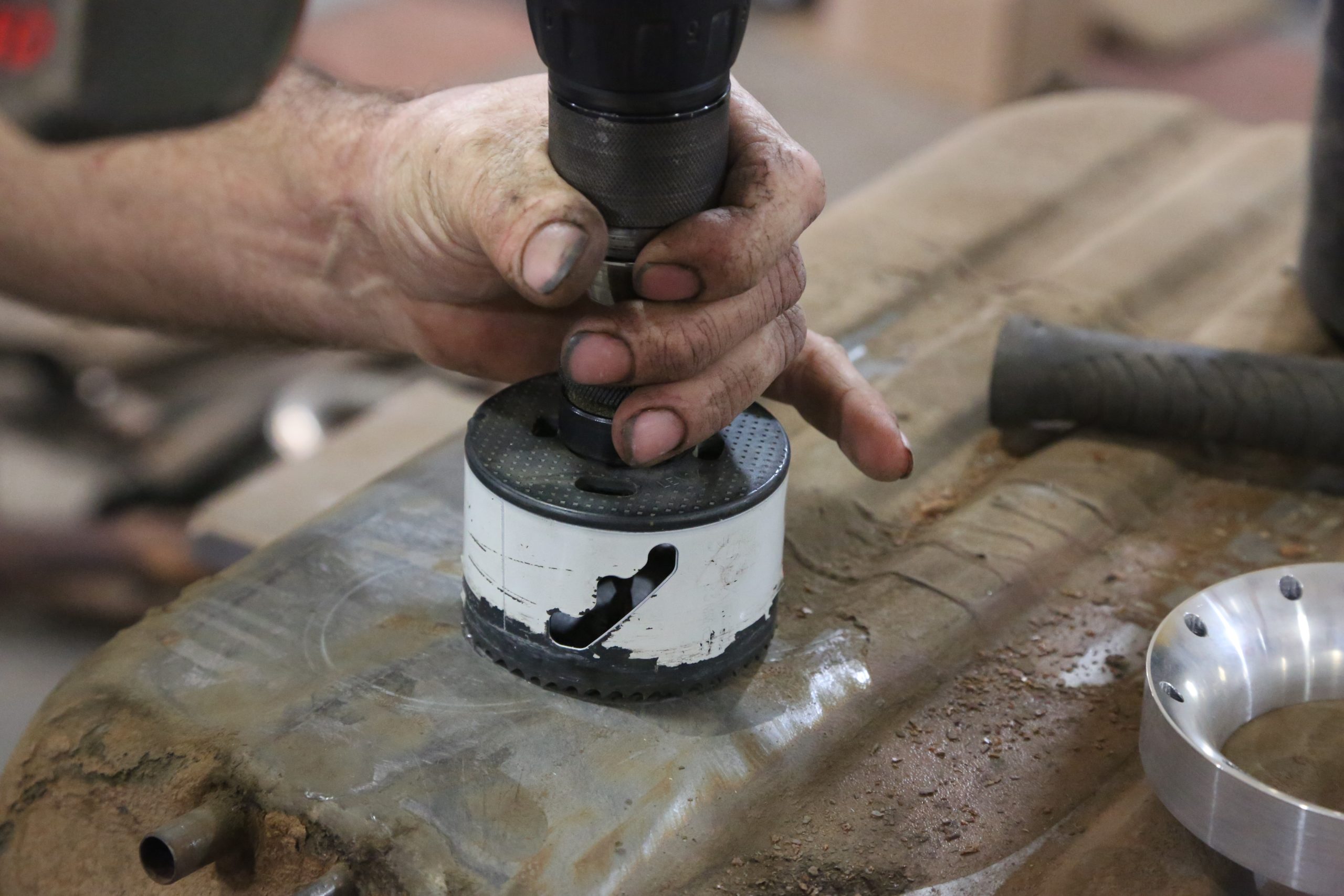
Installing the Aeromotive Dual Phantom In-Tank pump assembly is very straightforward. Doing the install with the tank on a work bench is about a two hour job. The kit comes with a drill jig and the correct drill bit for the module mounting ring. You’ll need a 3-1/4 inch hole saw, a drill, a shop vac to collect the metal shavings, and basic hand tools. A die-grinder, rotary tool, or file is recommended to widen the hole to get the module into the tank and clean up the edges after drilling.
The Phantom systems come with a foam baffle to ensure the pumps are always covered with fuel. The foam is cut to match the depth of the tank plus an additional one inch of clearance. In our case, that is eight inches. The baffle for the dual Phantom unit is larger than the one for the single pump kit, but it will fit through the same diameter hole. The drill jig also serves as a guide to help facilitate the installation of the baffle.
We recommend filling the tank when fuel level goes below the quarter-full mark. In-tank pumps require fuel to stay cool, and running less than quarter-tank will lead to premature failure.
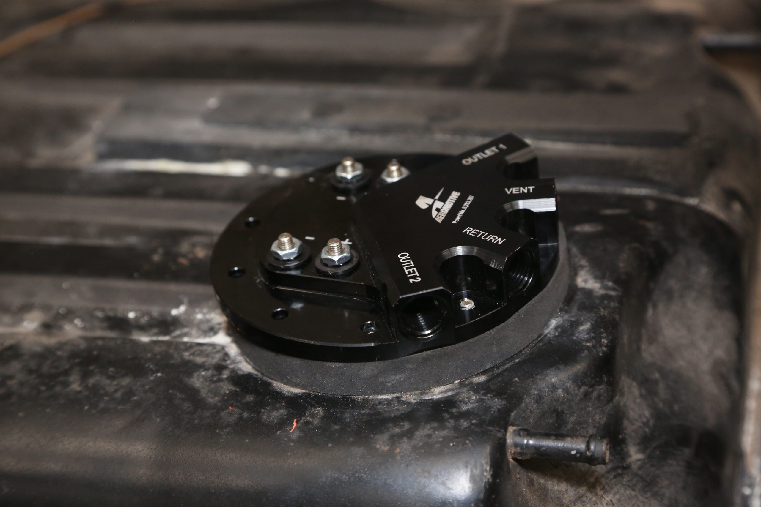
As far as plumbing is concerned, the Dual Phantom system has two output ports, one vent port, and one return port. These are -6 AN O-ring ports that require specific O-ring fittings. DO NOT use standard -6 AN fittings or you’ll have big leaks!
If you use the Aeromotive FSPC control module, the pumps are wired directly to it as the module controls amperage and voltage. Otherwise, the two pumps need separate relays and fuse protection. Each pump pulls about 13 amps at 40 PSI, so a minimum of a 20 amp fuse and 12 gauge wire is required.
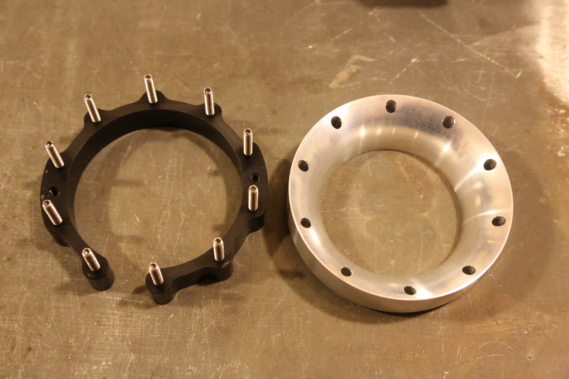
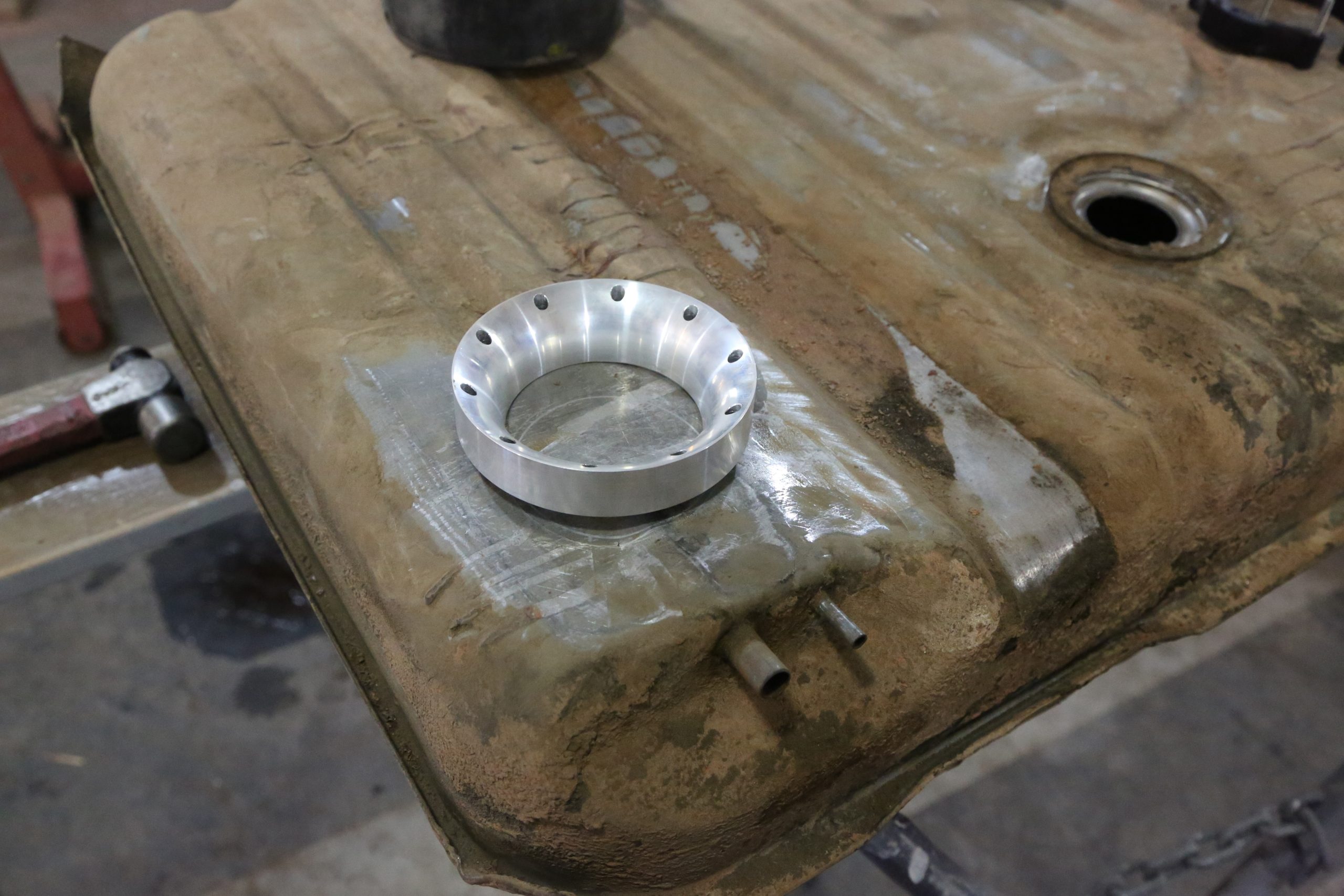
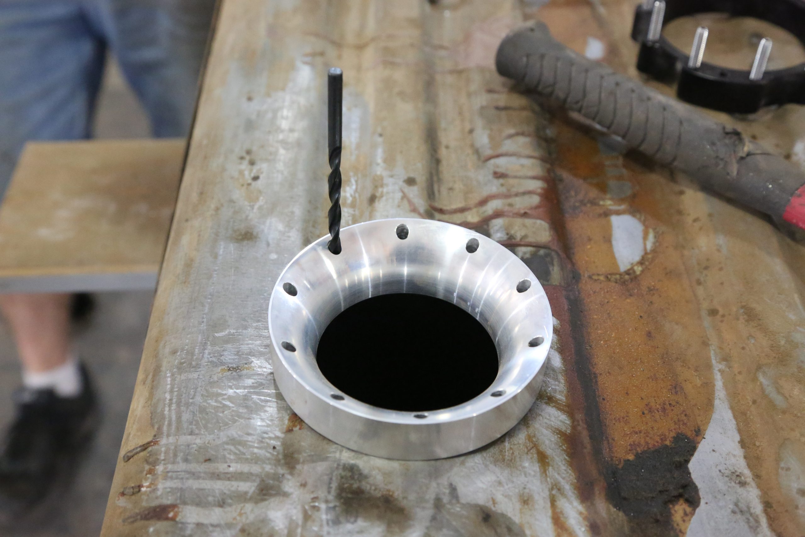
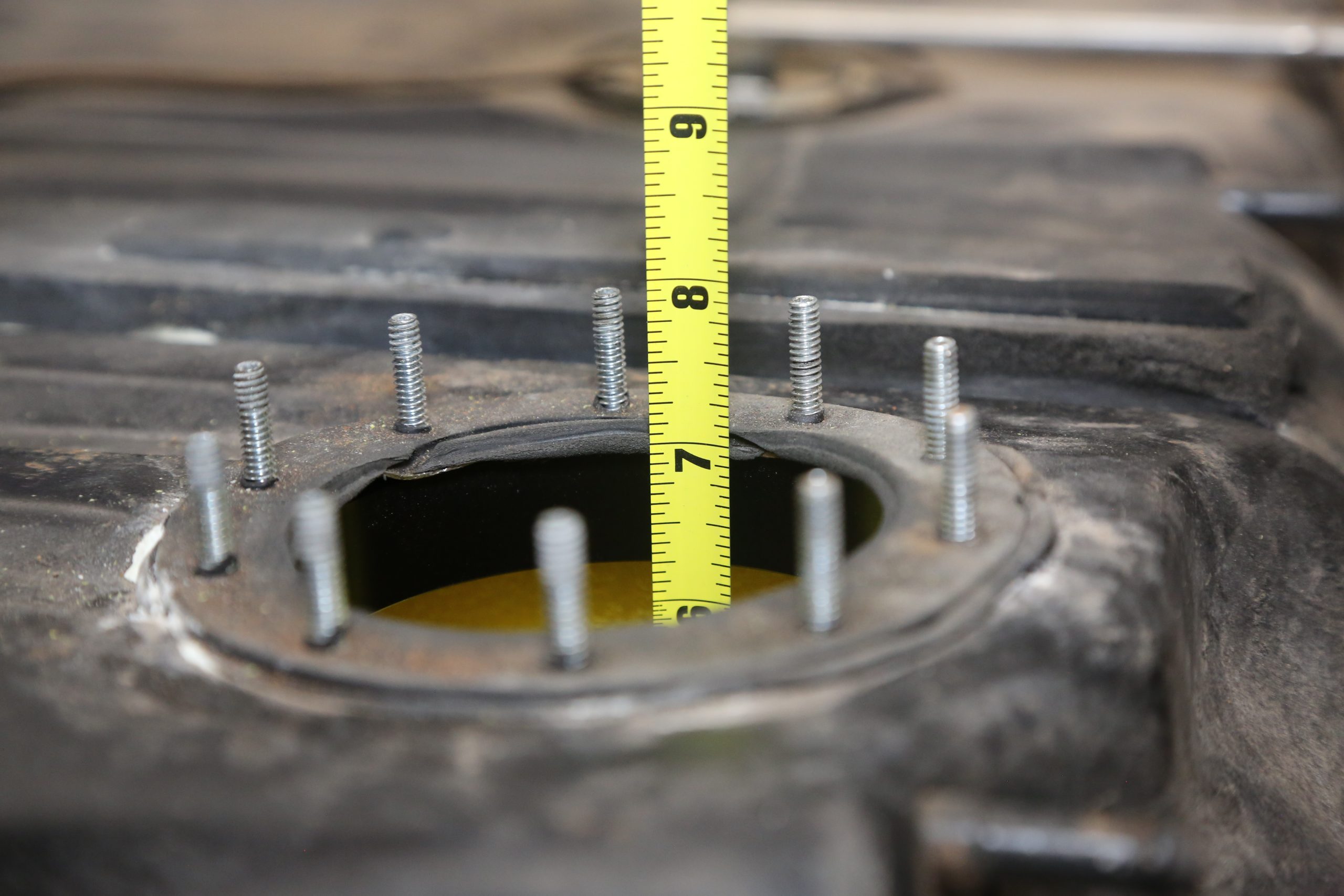
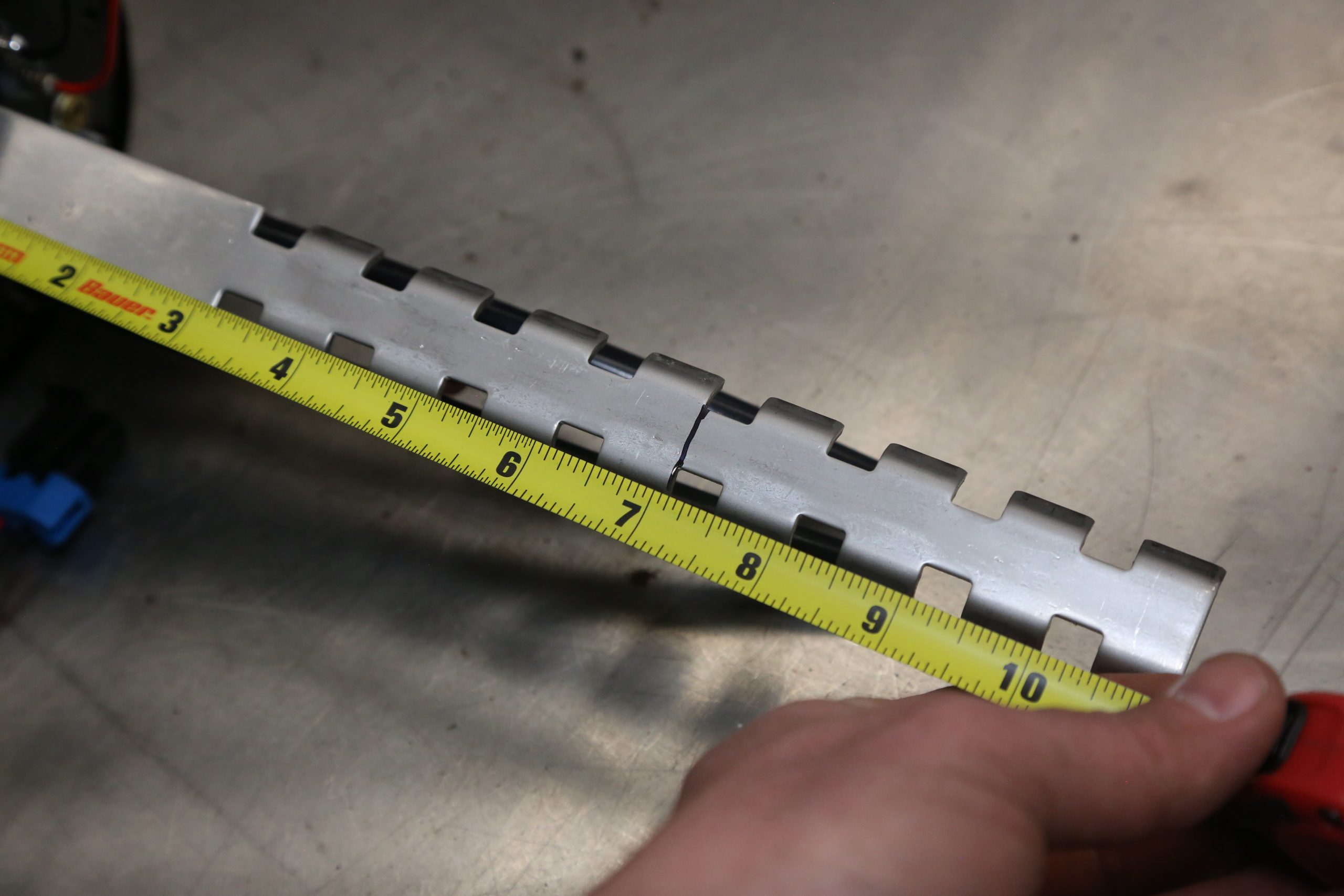
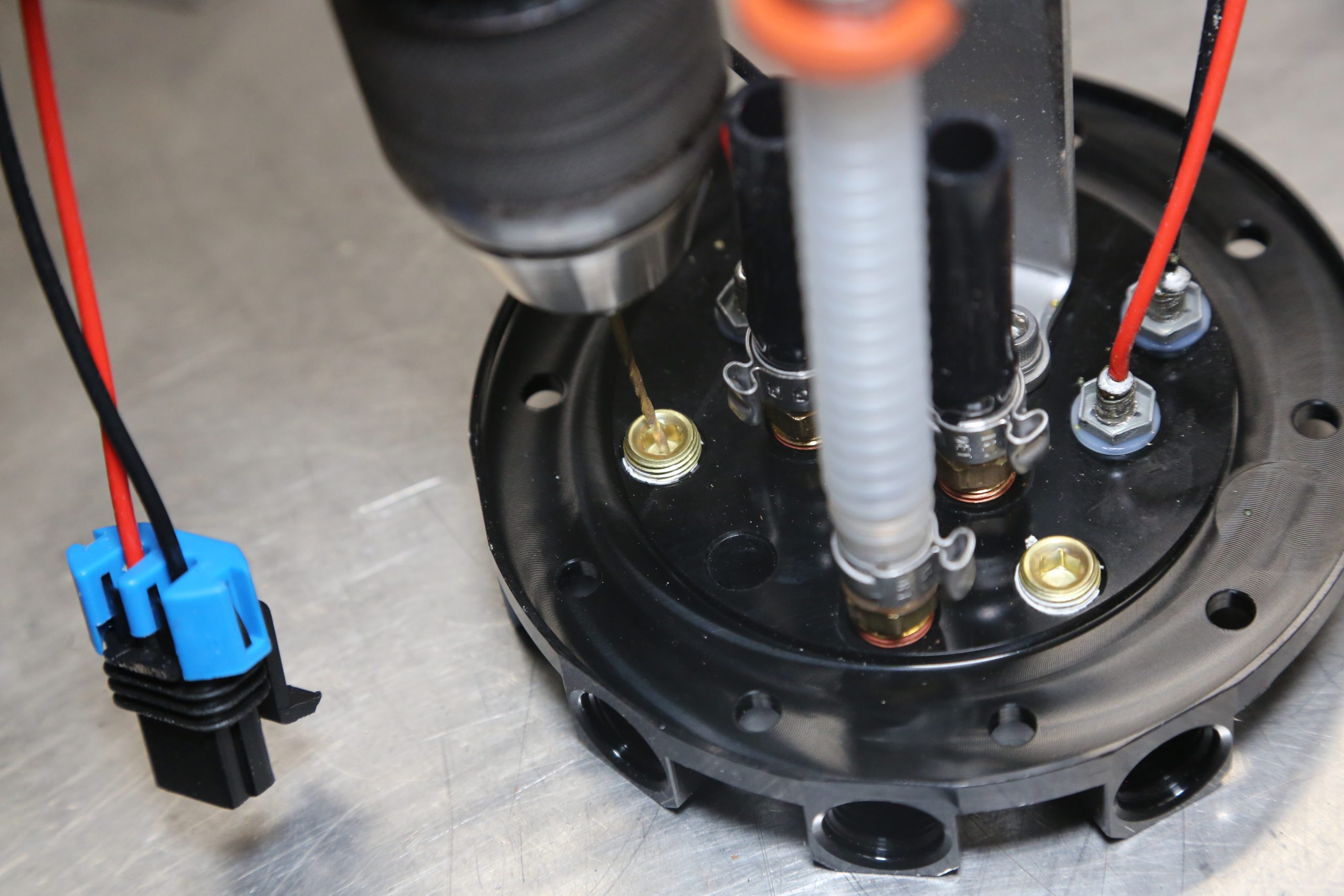
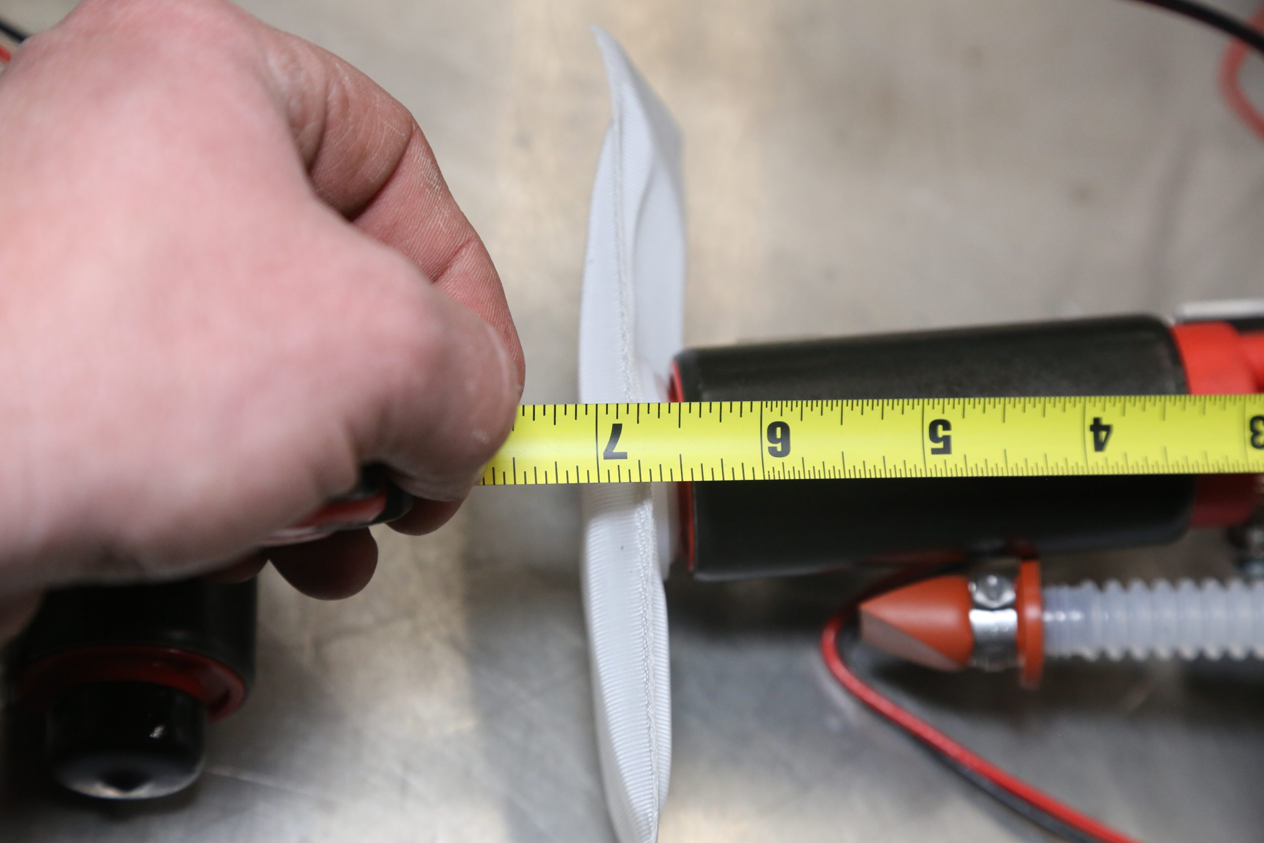
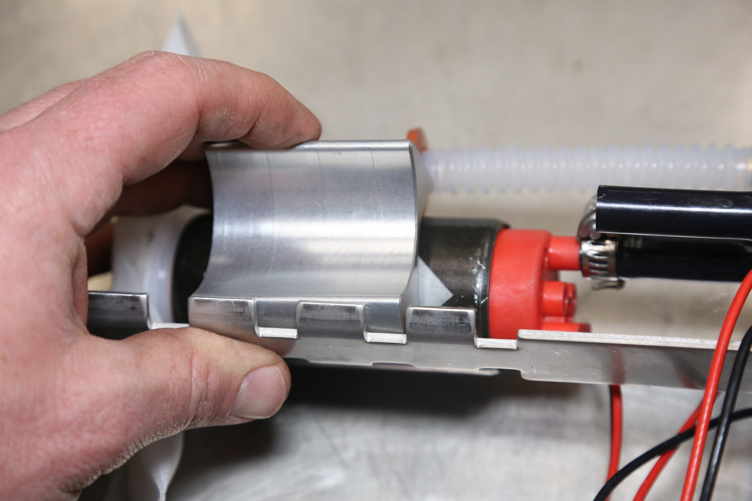
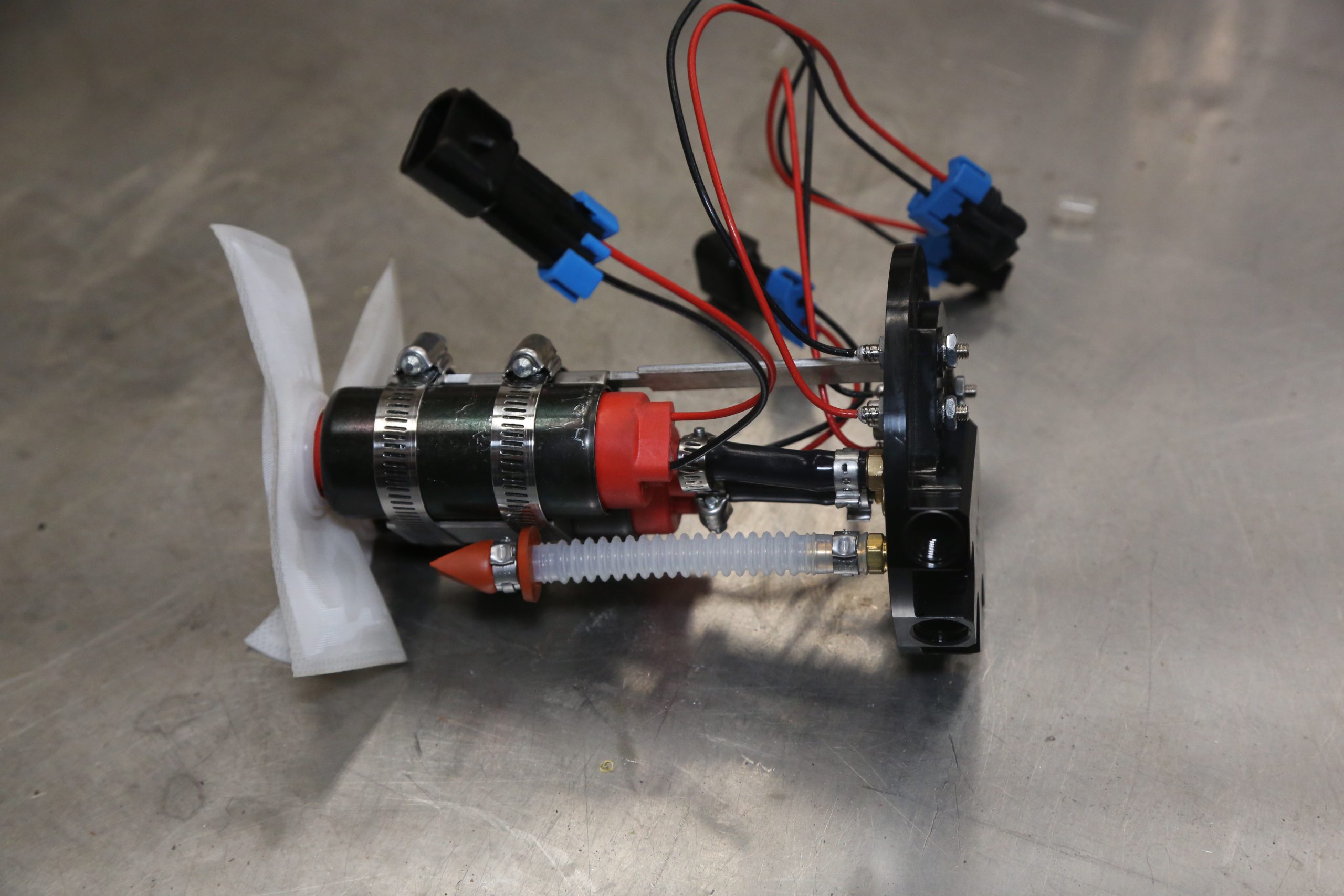
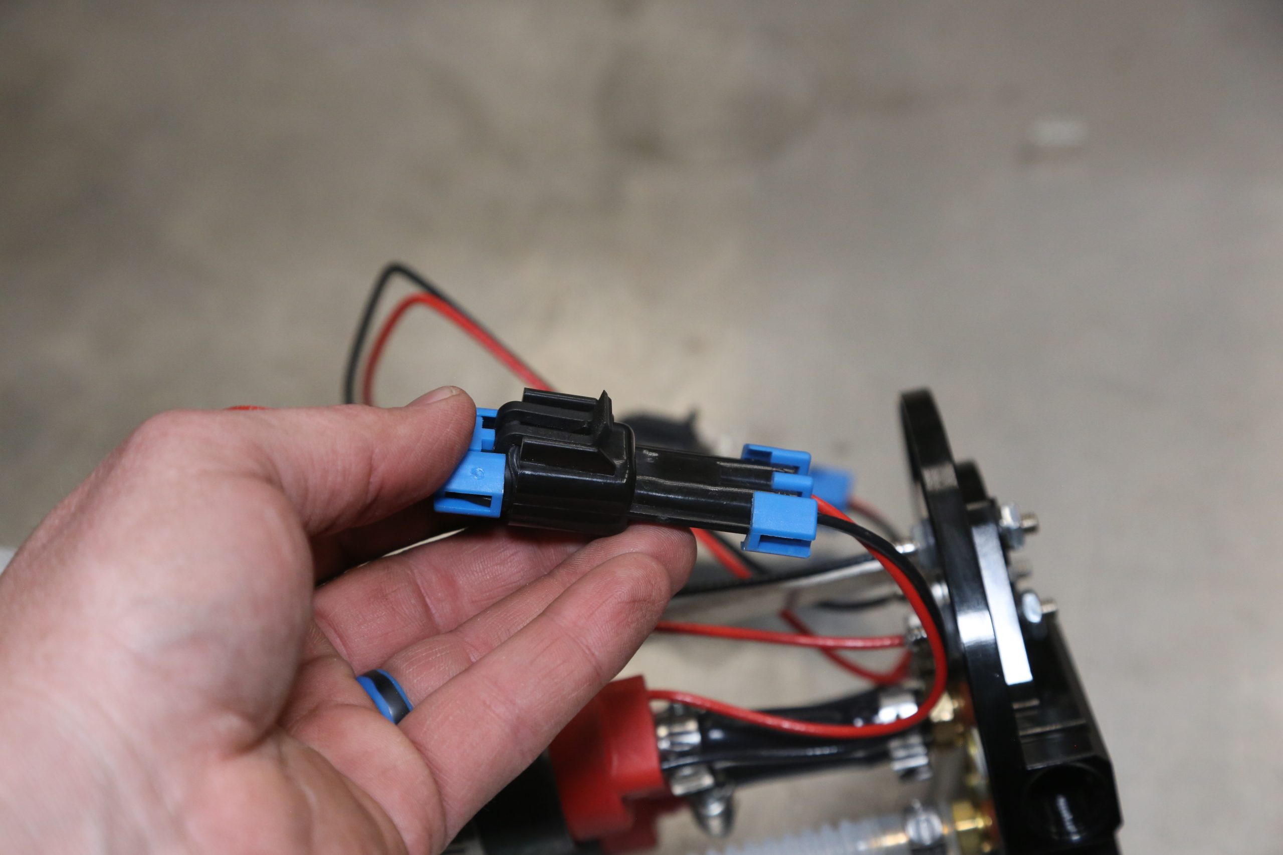
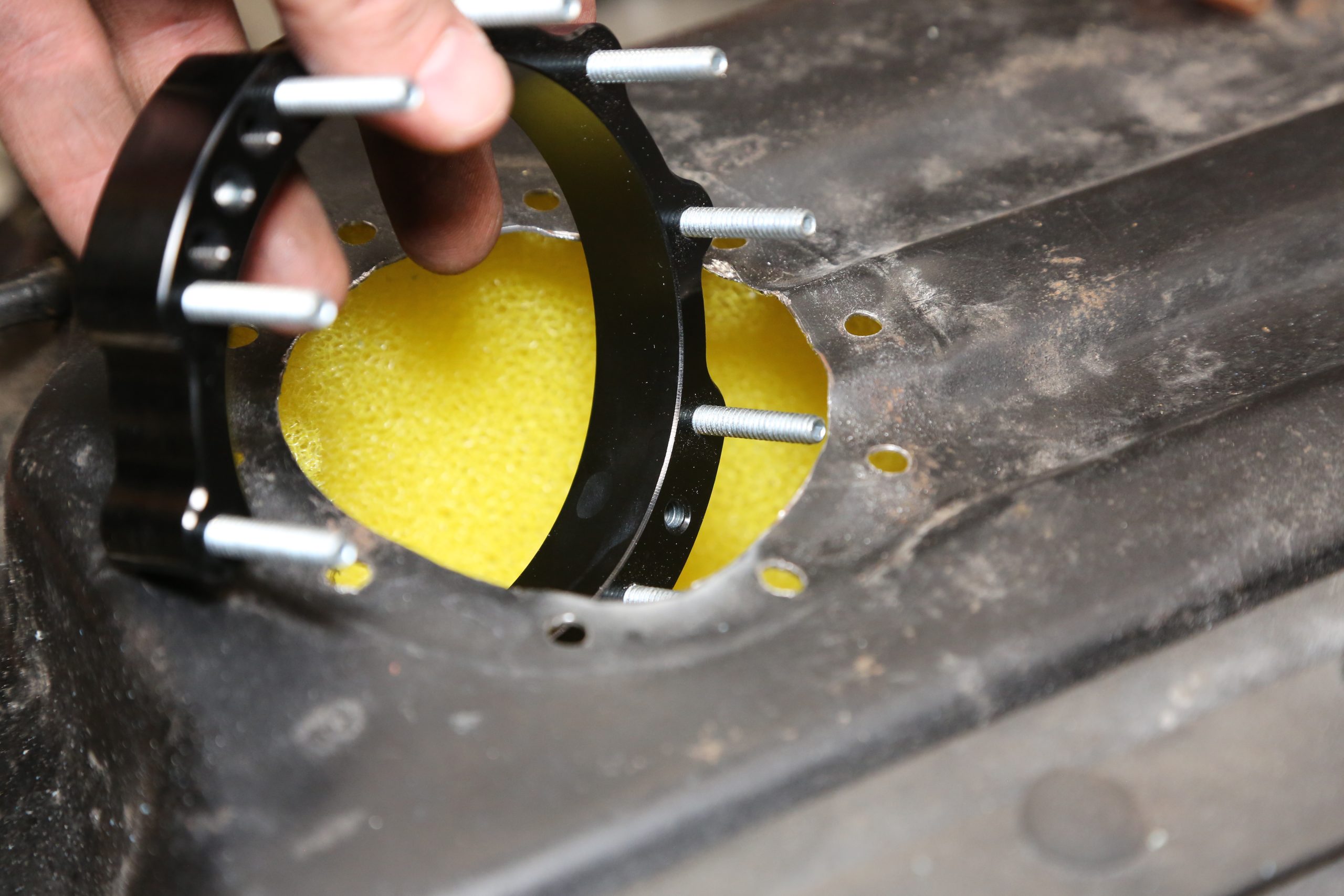
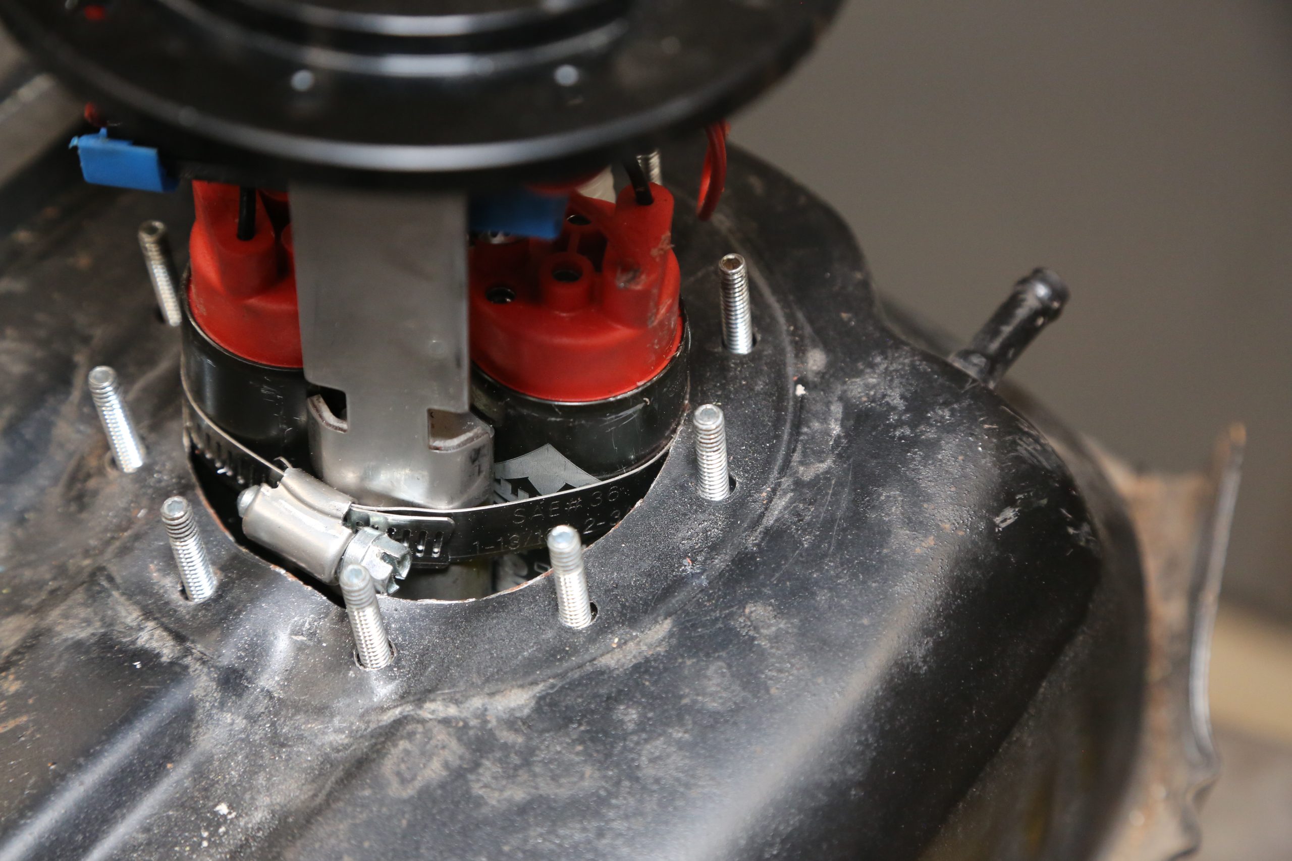
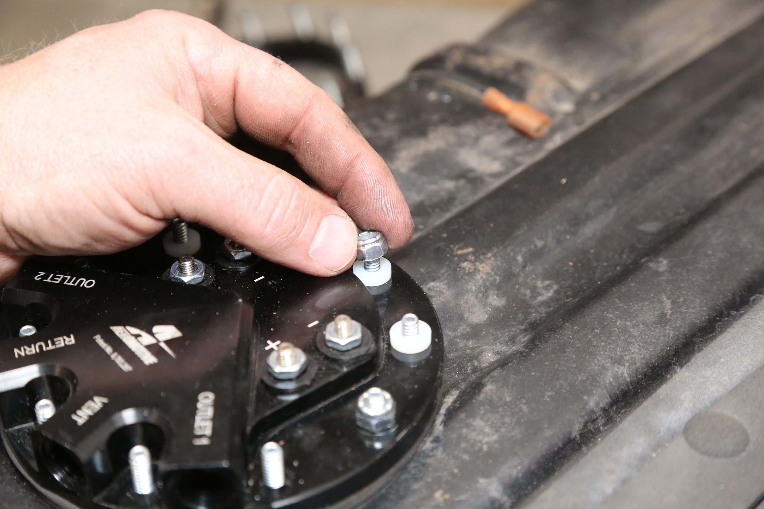
This is the stud ring and the drill jig from the single pump installation we did several years ago for our Buick GS. Phantom systems now come with a plastic drill jig. Before starting the installation, the tank must be empty. We recommend rinsing the tank out with water and drying it with compressed air. (Image/Jefferson Bryant)Selecting the location for the fuel pump(s) is critical. The Aeromotive Phantom module has a tank depth range of six to 11 inches, so you have to find the best location in your tank that is at least six inches deep. Our GM A-body tank is seven inches at its deepest point, which is the side towards the front of the car. We opted to put the module in the passenger side of the tank. There are two vents near the location, so we pulled the position back a little bit to ensure good clearance. (Image/Jefferson Bryant)We used a bi-metal hole saw to cut the tank. The Phantom system requires a fairly flat mounting surface. Corrugations up to a quarter inch deep are acceptable as the high-density rubber gasket can easily conform to seal. This part of our tank has minimal corrugations and worked out well. (Image/Jefferson Bryant)After dropping the drill jig into the hole, we drilled two holes across from each other and secured it with the supplied 10-24 bolts so it wouldn’t move. We then drilled the rest of the mounting holes using the supplied drill guide. After drilling, the tank must be vacuumed thoroughly to remove any metal shavings. (Image/Jefferson Bryant)The Phantom fuel module comes with a split stud ring that is slid into the tank. The ring studs are pushed up through the mounting holes. If you drop the drill jig over the studs and loosely thread a couple of nuts to hold it in place, you’ll protect both the foam baffle and your hand from the freshly cut metal. The baffle must fit so it is fully expanded and surrounds the stud ring. Even though we’ve already measured the tank depth and had the old single-pump baffle for comparison, we double-checked just to be sure. If you are doing a new Phantom installation, you have to measure tank depth with the baffle installed. (Image/Jefferson Bryant)Our tank depth measures seven inches. We transferred that measurement to module ‘backbone’ that the pumps secure to. We cut the backbone one notch above the seven inch mark to accommodate the two pump sock filters. (Image/Jefferson Bryant)The module has pre-installed pressure lines in the hat that must be trimmed to match the pump depth. The line is mildly flexible plastic that can be cut with a tool for cutting DOT air line or a razor blade. Side cutters can cut the line too—but you won’t get a clean, square cut. (Image/Jefferson Bryant)Because we are using an Aeromotive Fuel Pump Speed Controller (FPSC) to control fuel pump speed, we drilled the two brass plugs in the hat with a 1/32 inch drill bit. This serves to bleed off pressure when the demand for fuel drops. (Image/Jefferson Bryant)The pumps are assembled with the new sock filters. The bottom of the socks should just barely touch the tank floor. Once the socks are in place, we can secure the pumps with the included hose clamps. (Image/Jefferson Bryant)Aeromotive includes this little aluminum spacer to lock down the pumps and keep them separated so they can’t move around. The block rests on the module backbone. (Image/Jefferson Bryant)The Phantom module assembly is just about ready to go into the tank. The wires are left long to accommodate 11 inch deep tanks, but on a shallower tank, there is a fair amount of loose wire that you have to deal with. (Image/Jefferson Bryant)The wiring harness for each pump is a plug-in deal using standard Molex plugs—just snap them together and go. (Image/Jefferson Bryant)We decided to go ahead and swap out the stud ring for the new one just because it looks nicer. (Image/Jefferson Bryant)The dual pump module was a tight fit in the 3-1/4 inch hole. Rather than force it in, we pulled the pump and clearanced the hole on each side where the pumps hit. (Image/Jefferson Bryant)The thick foam gasket makes it really tricky to get the studs through the hat. We used a flat blade screwdriver under the gasket to catch a thread and put pressure on the ring so we could push the hat down enough to get a nut on two studs. (Image/Jefferson Bryant)The hat is secured with a series of 10-24 Nyloc nuts and nylon washers. The washers are required, do not skip them. Use a crisscross pattern to tighten the nuts. DO NOT overtighten or you risk breaking the studs. The sealing gasket should conform to the surface of the tank to seal any gaps. We didn’t have anything that would fit the studs between the ports, so we shaved down a 3/8 inch nut driver on the sander so we could tighten those nuts. (Image/Jefferson Bryant)There is not much room under a 1968-72 GM A-body to service the fuel tank. To make that easier, we terminated the wiring to a Metri-Pac plug and pre-plumbed the pump output ports to a Y-block. When we did the previous, single-pump Phantom install, we spaced the tank down with rubber strips to add about a half inch between the floor and the top of the tank. The vent port was connected to a vent line we had in the car already. The return line port was plugged. (Image/Jefferson Bryant)
Jefferson Bryant has been a full-time automotive journalist since 2003. He has written countless how-to articles, nine books, and built several award-winning vehicles.
Hello. I am currently installing this exact set up in a boyds welding tank. It will be feeding a 408 stroker with an LSA blower running about 12psi boost. Shooting for similar HP goals.
I had questions regarding the ability of the Aeromotive FPSC to control 2, 340lph pumps at once. You are the only one I can find online attempting this. Everything else I can find is for a single pump only.
Your article kind of ended without any info on your installation of the FPSC. How did it work? No issues with it running 2 pumps? Maybe a quick sketch of your wiring diagram? Thanks for any further info on that part of your install.
Can I replace my in tank an 1,000 with this. I’m using a automotive fuel regulator with a Pro Flow efi on a gen. 6 502 Max pressure needed is 70lb.
Hello. I am currently installing this exact set up in a boyds welding tank. It will be feeding a 408 stroker with an LSA blower running about 12psi boost. Shooting for similar HP goals.
I had questions regarding the ability of the Aeromotive FPSC to control 2, 340lph pumps at once. You are the only one I can find online attempting this. Everything else I can find is for a single pump only.
Your article kind of ended without any info on your installation of the FPSC. How did it work? No issues with it running 2 pumps? Maybe a quick sketch of your wiring diagram? Thanks for any further info on that part of your install.