Electrical relays are one of the most versatile components in your vehicle’s electrical system. A type of electro-mechanical switch used to control power or ground connections, there are really no bounds to the usefulness of relays. Not only do they help you manage the current load on individual circuits, they can function as automatic switches for all manner of electrical components in your vehicle.
We are going to take a deep dive into the world of automotive relays to explain what they are, how to use them, and even build trick circuits with them.
This article is part of a series of general electrical 101 articles, you can see Jefferson Bryant’s write-up on vehicle electrical fuses here.
Types of Relays
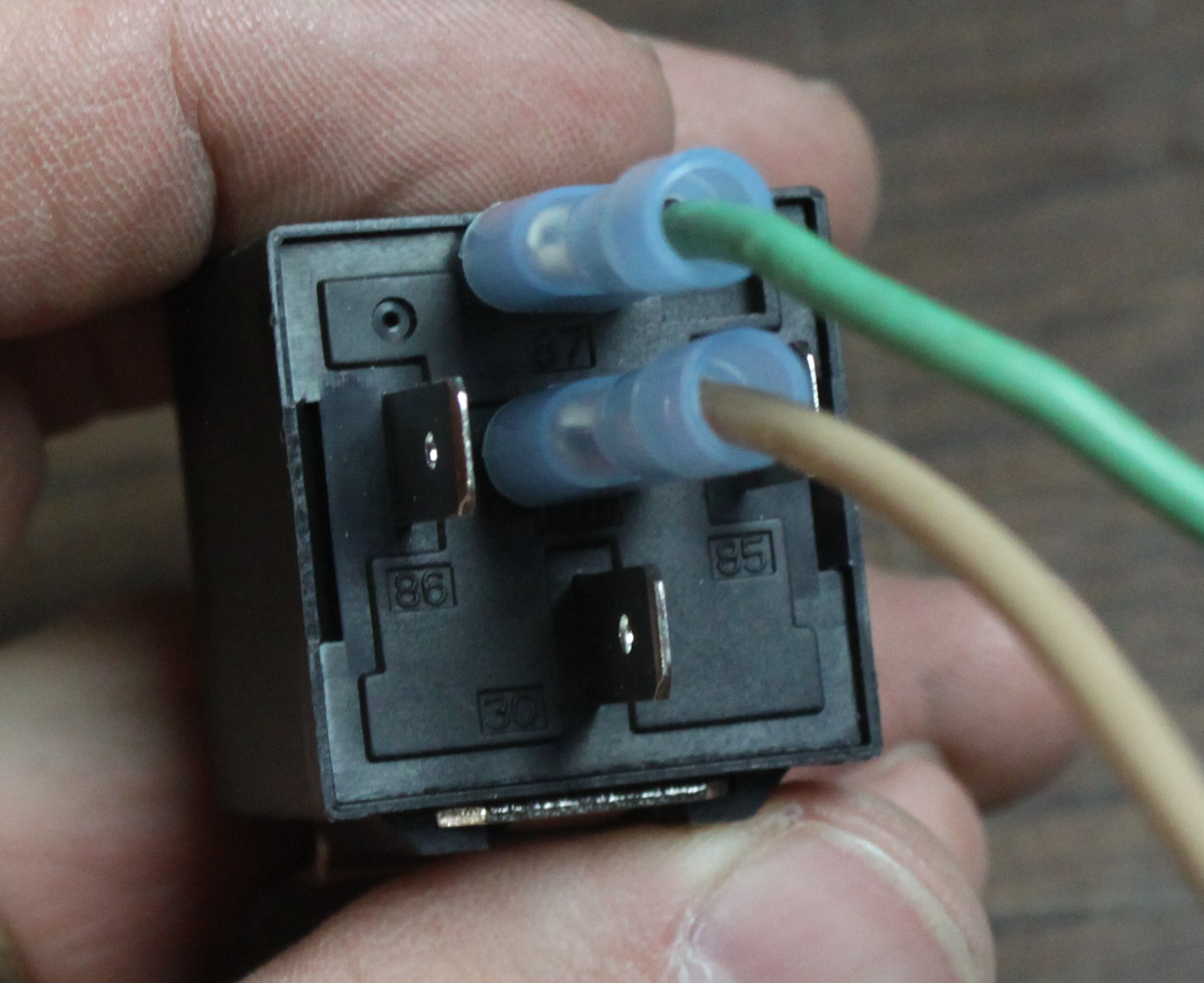
There are several types of ISO mini, or standard automotive relays. Inside a typical ISO mini relay is an electromagnet powered by terminals 85 and 86. When engaged, the magnet pulls on a small strip of metal called a contactor. The manner of connection is determined by the relay type:
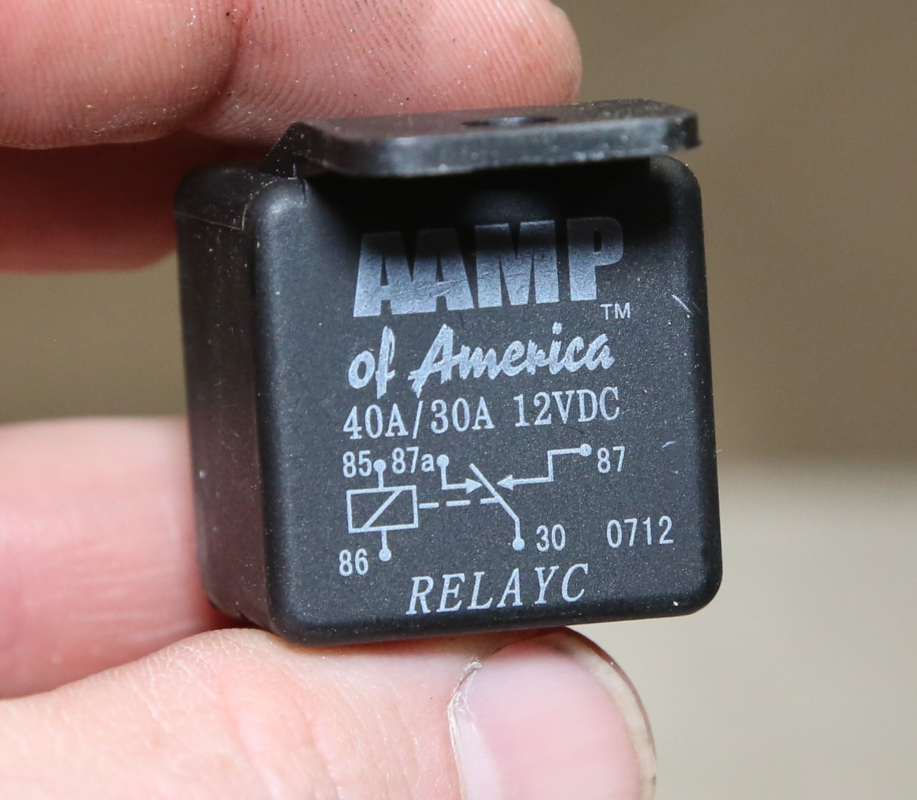
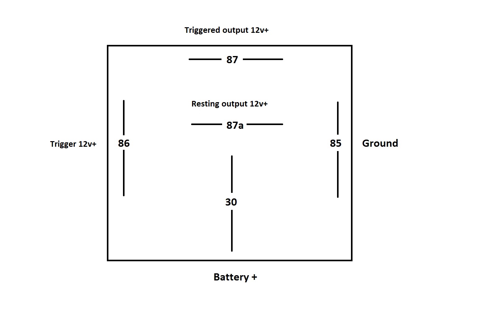
SPDT (Single-Pole Double-Throw): Also known as a Bosch or “change-over” relay, this is the most common type of relay that you will find in the automotive environment. These relays have five terminals–85, 86, 87, 87a, and 30. They are called change-over relays because the two switched terminals (87 and 87a) are both powered, but not at the same time.
When non-energized, meaning there is no power going to the trigger terminals (85 or 86), the feed terminal (30) is connected to the normally closed terminal (87a). When the relay is energized, then 87a is switched off and 87 is switched on. The 87a terminal is not used that often in most automotive circuits.

SPST (Single-Pole Single-Throw): These are just like the SPDT relay, except they are four-terminal units in a normally open configuration only. On these relays, there is no 87a. This is the most commonly used configuration, but these are less common in the average hobbyist’s supply drawer, because the SPDT works just the same and has the ability to do more. OEM relays are almost always SPST. You might see these as part of an electrical installation kit for aftermarket equipment like lights, fuel pumps, etc.
Dual Make SPST: These are just SPST relays with two independent outputs. The output terminals are 87 and 87b. These relays are used for circuits that are typically isolated from each other. This is a common relay for German vehicles.
Time-Delay SPDT: A time-delay SPDT relay is useful If you need to maintain power for a short time after killing the circuit. Using solid-state timing circuitry, these relays have variable timing control for accurate control of a circuit. These are usually SPDT change-over relays, so you have lots of options. When you buy one of these, you want to look for diode-isolated pieces, as you need a diode to eliminate timer interference issues. These are not cheap, typically costing about $20 to $30 each.
Diode-Protected: Any SPDT or SPST relay can be diode-protected. This is either built into the relay (it will be noted on the body) or you can add one. A diode protects the circuit from voltage spikes during the switching operation. Some sensitive electronics really don’t like being switched off or on quickly, and the voltage spike from a relay switching can hit 100 volts or more, but at very low amperage. This can damage electronics such as car alarm brains, or other control modules.
Thes relays are expensive. You can make your own by putting a diode (such as a 1N4007) between the 85 and 86 terminals, with the stripe side (cathode side) to the negative terminal 85 and the anode side (no stripe) to the positive 86 terminal.
IMPORTANT NOTE: Relays are not polarized, meaning you can put positive or negative on the trigger terminals (85 and 86). If the relay is diode protected, 86 is always positive and 85 is always negative, regardless of whether the trigger is positive or negative.
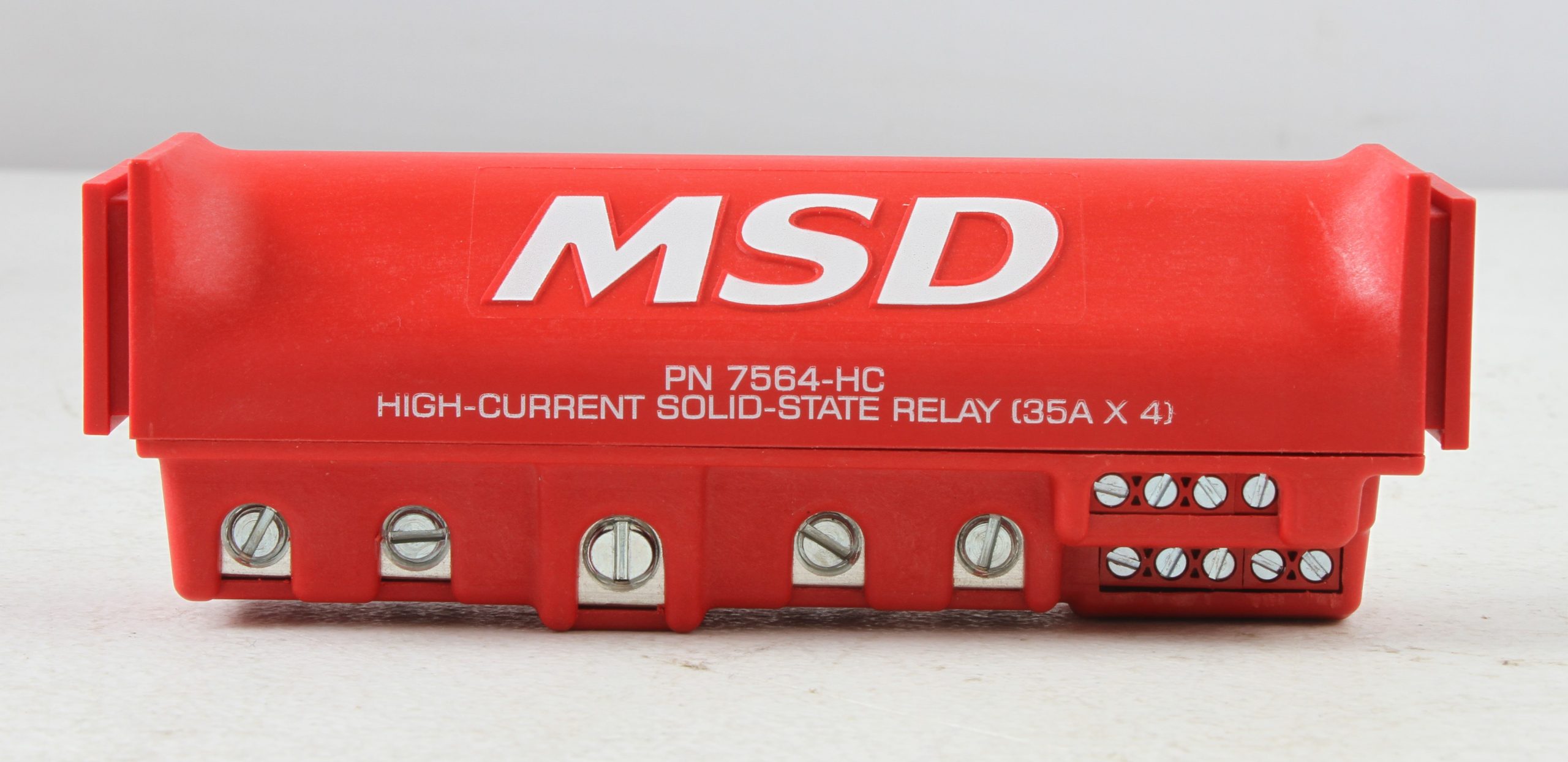
Solid-State Relay: These operate similarly to electro-mechanical relays, but use integrated circuits instead of the electro-magnetic switch to control power distribution. These are clean, easy to use, and very efficient. They have the ability to completely sever the connection with no potential to arc. They are also much faster on the connect and disconnect that EM relays, but they cost a lot more too.
Flasher Relays
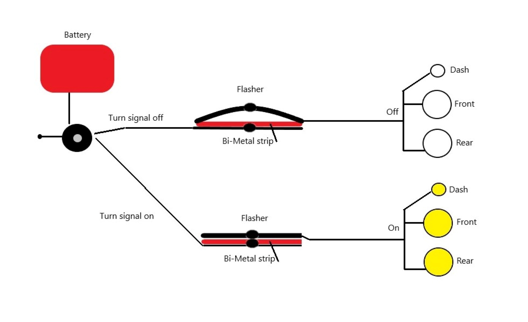
All vehicles use flasher relays to control the turn signals. The two-terminal flasher is the most common. One terminal is for the power input, the other is for the output. Three-terminal flashers have a second output post for an indicator. Most cars use the two-terminal flasher and the dash indicator is integrated into the rest of the turn-signal wiring.
A flasher relay is an automatic relay—it will switch the circuit off and on continuously until the main circuit is turned off. That’s the click that you hear when your flashers are on.
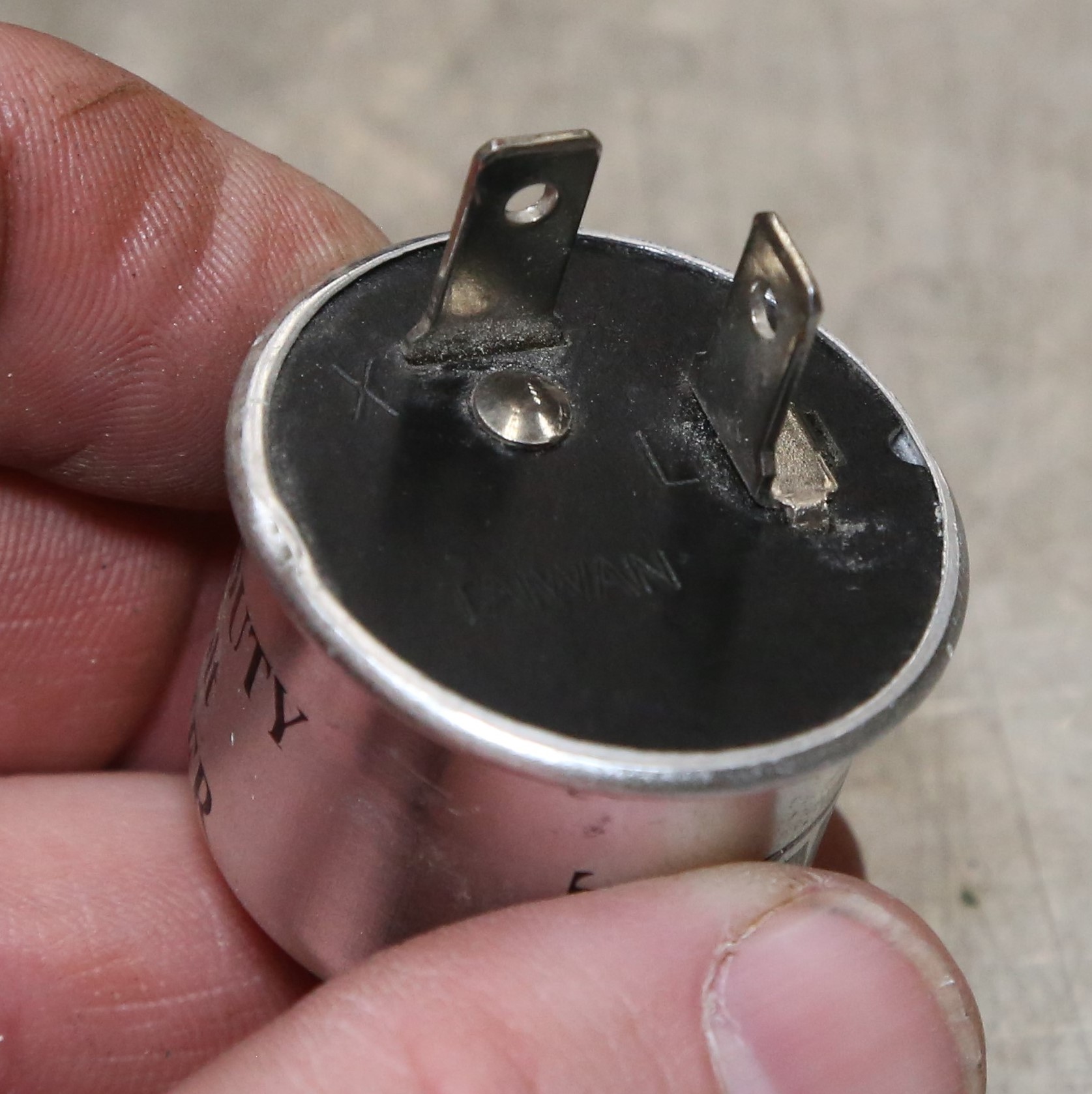
Thermal flashers are the most common flasher type. The two (or three) terminals are normally open. A bi-metal strip that heats up when the circuit is energized. This heat warms the output contactor until it snaps closed, lighting the bulb. When the contact is made, the power to the heat strip stops flowing and the heat strip cools, which cools the output contactor. Once the contactor cools enough, it springs back to its curved shape, and the circuit opens. The heat strip starts heating again—wash, rinse, repeat.
This action is caused by the high-resistance of the bi-metal strip as electricity flows through the path of least resistance. Because the resistance is so high, the current that flows through the bi-metal strip turns into heat and doesn’t get through the strip to light the bulb. The downside is the flashers eventually wear out when the bi-metal burns up or the spring metal breaks.
This is also why your turn signals flash more quickly when one bulb is out. When a bulb is out, the current flowing through the relay is reduced. The bi-metal strip heats and cools much faster, causing the reaction to be much faster.
Electro-mechanical flashers turn the bulbs off and on in a timed sequence. Instead of using a heat strip, these have solid-state circuitry to measure current flow, a timer mechanism, and a transistor that opens and closes the circuit, flashing the lights. If the current flow is less than it should be, the timer goes to fast-flash mode. This is not a safety feature; it does this to emulate the thermal flasher fast-blink to notify the driver there is problem with a bulb. These flasher even have an audible click to let you know it is working, just like the thermal flashers do. Electro-mechanical flashers began taking over the flasher duties in the early 1990s.
LED flashers came about as bulb technology moved forward. LED lights require very little current to operate, so a typical mechanical flasher doesn’t work. LED flashers use an integrated chip on a circuit board. They can control many LEDs since the current draw is so low. Thermal and EM flashers don’t work with LED turn signals because there isn’t enough current to operate the thermal heat strip or trigger the mechanism in an EM flasher.
Wig-Wag flasher are solid-state flashers that alternate the output from one post to the other. When activated, one side lights; when it turns off, the other side gets power and lights up, and the sequence is repeated over and over. You see these lights on police cars, emergency response vehicles, service trucks, etc. There are all kinds of uses if you want to get creative.
How To Wire a Relay
Now that we have the types and functions out of the way, let’s get into how to wire and use relays. We are focusing on SPDT/SPST relays as opposed to flashers for this. Flashers are very simple and used almost exclusively for turn signals.
All automotive relays work on 12 volt power (there are relays for 6 volt electrical systems, but most commonly available relays are designed for 12 volts). You need 12 volt positive and ground to trigger any relay. This is done on terminals 85 and 86. The relays can be triggered on either side of the circuit, but you need positive and negative connections to energize the circuit. Most relays are wired so terminal 86 is positive, which is good rule of thumb to follow.
The pass-through circuit can be positive or negative. It doesn’t matter to the relay—it is simply making a connection to flow electricity. Typically, relays are used to move current draw from one circuit to another dedicated circuit. Let’s say you install a larger electric fuel pump in your late model car. The new pump needs 30 amps of current to operate, but the original fuel pump wire in the car’s engine control module (ECM) is only 12 gauge, which can’t safely handle 30 amps of current (12 gauge wire is limited to 20 amps). Adding a relay allows you to run the original ECM power feed into the trigger for the relay and wire the pass-through (terminals 30 and 87) to a 10 gauge or larger power feed wire that connects to the battery.
Here are the terminations for an SPDT and a SPST relay:
5-Pin SPDT Relay Termination
85: Ground
86: Positive 12 volt
87: Connects to terminal 30 when the relay is triggered
87a: Connected to terminal 30 when the relay is off
30: Power or ground source
4-Pin SPST Relay Termination
85: Ground
86: Positive 12 volt
87: Connects to terminal 30 when the relay is triggered
30: Power or ground source
You can tie 86 and 30 together is you are using a ground trigger. If you are using the relay to flow positive voltage, then the wire between terminal 30 and the battery (or battery source) must be fused to the appropriate level for the circuit. Ground pass-through does not need a fuse, but the power side of the component’s circuit should be properly fused.
Bosch-type ISO mini relays are typically available in power ratings 30/20 and 40/30 amps. The first number is the amp rating for terminal 87, the second number is for 87a (if so equipped). The maximium amperage an ISO mini relay can handle is 40 amps. If you need to power a higher-draw circuit, you need a high-amp relay to handle the current draw. An example of a high-amp relay is a Ford remote starter solenoid. This is actually just a giant relay.
The current draw for the trigger side is very small (less than 0.2 amps) so you don’t really need to fuse this side of the relay. The cool thing is that most trigger circuits provide up to five amps on the supply side. You can wire two or three relays to the same trigger wire, trigger multiple relays off a single relay, or feed multiple circuits off the same relay provided the total amp draw does not exceed the relay’s rating.
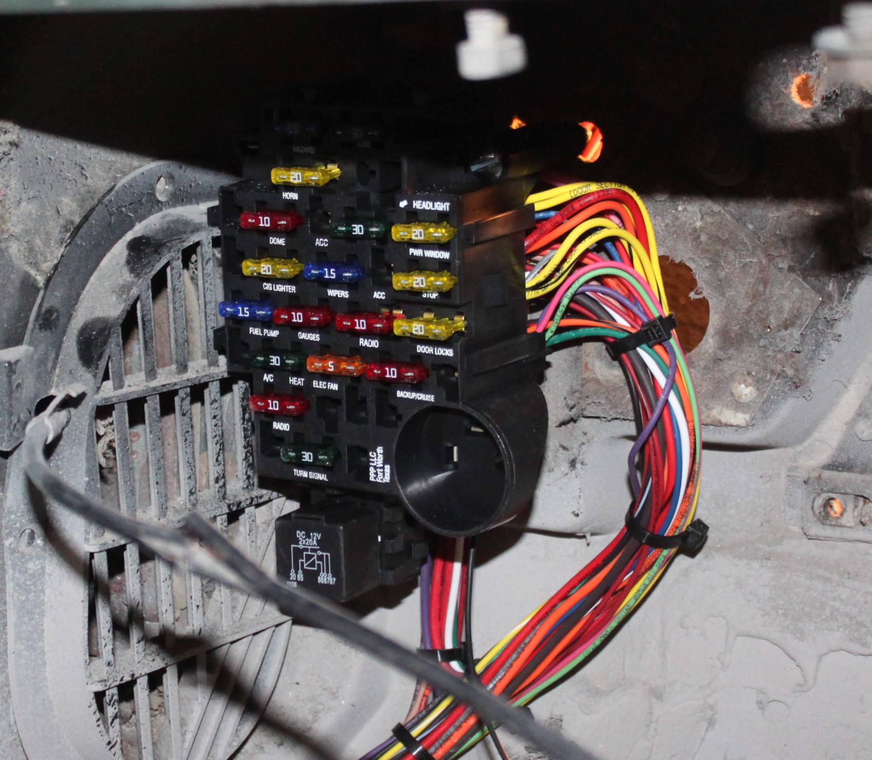
You can wire a relay with standard spade terminals or with sockets. Sockets look good, but the wires are going to be whatever color the manufacturer chooses, so you might have some issue keeping your color codes straight. OEMs use sockets built into the fuse blocks or sockets with loose wire.
A Note About Grounds
The ground side in automotive applications is too often dismissed as unimportant, but this cannot be further from the truth. A bad ground is the number one cause of problems in your vehicle’s electrical system. Always maintain the same size ground cable as the power side, and always ensure that the ground point to the body, frame, or engine is clean with no rust, paint, or other coatings that could cause an issue with the connection.
You may enjoy this article too: A Quick Guide to Electrical System Grounding
2 Basic Examples for Wiring a Circuit with a Relay
Negative Trigger to Positive
Example: you have an ECM circuit that has a negative trigger but you need a positive trigger for, say, a cooling fan control module.
85: negative trigger feed from ECM
86: 12 volt positive tied to term 30
87:-12 volt positive to fan control module
30: 12 volt positive to battery
Positive Trigger to Negative Trigger
Example: you have a car alarm module that has a positive trigger, but you need to honk the horn, which is a negative trigger.
85: Tied to terminal 30
86: Positive trigger input from module
87: Ground feed to horn
30: Grounded to battery, body, or frame
Some Handy Circuits You Can Make with Just a Few Relays
Accessory Circuit
Most cars built in the early 2000s have a radio-on circuit that keeps the radio on until you open the door. This can be used to trigger all kinds of stuff—lights are a good example. All it requires is two SPDT five-pin relays.
If your radio is wired to the ‘run’ side of the ignition switch and not the accessory side, this circuit can cause a backfeed that keeps your engine running. In this case, you will need to isolate the ignition circuit from the accessory circuit to make this work.
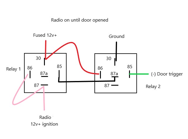
Relay 1
85 to 87A of Relay 2 (ground)
86: Tied to 87 of Relay 1
87: Radio’s ignition switch wire
30: 12 volt positive fused, tied to 86 on Relay 2
Relay 2
85: Negative door trigger
86: Tied to 12 volt positive via 30 on Relay 1
87A: Tied to 85 on Relay 1 (ground)
30: Grounded to battery, body, or frame
No-Start Circuit
You may recall the scene in “Back To The Future II” when young Biff asks old Biff how he started his car, as nobody knew how to start that car but him. You can create a no-start circuit for your car so that it cannot be started unless you hit a hidden momentary switch first. All you need is two 40 amp relays and some wire.
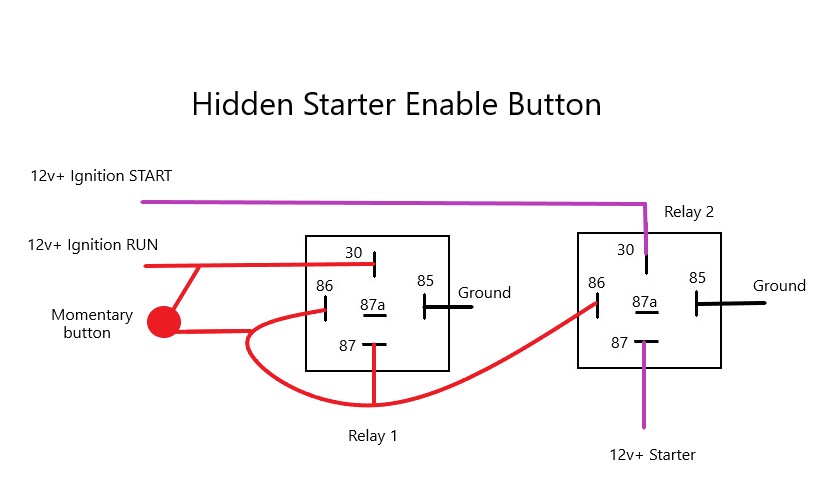
Relay 1
85: Ground
86: One side of the momentary switch (mut be momentary, not latched)
87: Tied to 86 on BOTH relays
30: 12 volt positive from ignition switch RUN pole and the other side of the momentary switch
Relay 2
85: Ground
86: Connected to 86 of Relay 1
87: 12 volt positive to starter motor trigger
30: 12 volt positive to ignition switch START pole
When wired this way, the two relays form a module that controls the starter trigger wire. To start the engine, put the key in the ignition and turn it to the RUN position, then press and release the momentary switch. This activates the relay circuit; when you turn the key to the START position, the starter triggers. The momentary switch activates Relay 1, which sends 12 volt positive current from 87 to 86 on both relays to keep the circuit closed after the switch is released. This also powers up Relay 2, which allows current to flow from the ignition switch to the starter.
Once the ignition switch is turned to the OFF position, the relays are shut off and you have to use the same procedure to restart the engine. In the event that a relay dies, you can always bypass the circuit by reconnecting the starter wire from the ignition to the starter side.
***
Relays are so much more than just a way power circuits and flash turn signals. Grab a few relays and some terminals and start experimenting with various circuits using a battery and a multimeter at your work bench.
You’ll be surprised what you can come up with!
I have a relay or pre-heating timer and they stop the production so I don’t know how to fix it
Relay 28521-54430 is for a Japanese Toyota Hilux .
have a Rav4 95, when i use my indicators or reverse all the electrics go off, thinking it was relay problem, I changed three relays:- ST 28300-10020:- EG main 85925-17010 :-H-LP 90927-02006, this I thought had righted it but happened again but after a few minutes or up to ten minutes everything comes back on again. so where am I going wrong?