A huge majority of drag race cars are equipped with electric fuel pumps. No secret, and more than a few street cars have them too. Of course, EFI cars are all fitted with electric pumps.
There’s good reason for all of this.
One is the need for higher pressure (EFI systems). Another is the consistency of an electric setup. With a good regulator, you’ll almost always have steady fuel pressure. With an electric pump fitted with an external fuel pressure regulator, you can easily adjust the pressure. Little things are easier too. A simple, but good example is setting float levels on a Holley carburetor. With a mechanical pump, the floats on a Holley carb must be set with the engine running. You don’t have to do that with an electric pump.
On the flipside, if you have a Chevy with a roller camshaft mixed in with a mechanical fuel pump, the pump pushrod can, in some cases, become a dicey proposition. A steel roller cam will wear out a conventional pushrod in a heartbeat. Options are pretty small. You can read my earlier article here for more info on fuel pump pushrods.
Fair enough. What’s really involved in the switch from a mechanical fuel pump to an electric?
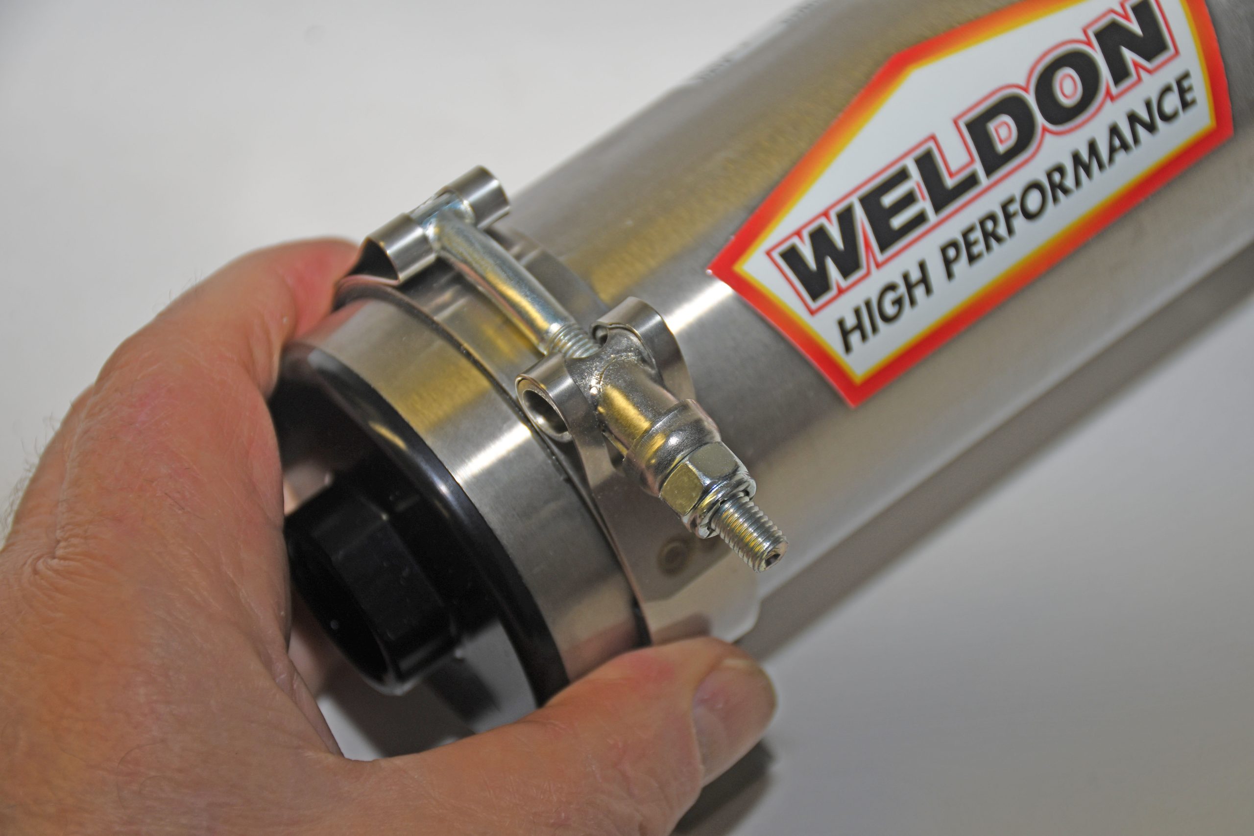
You’ll obviously need an electric fuel pump and in most cases, an external regulator, additional plumbing, a fuel pressure gauge, an appropriate switch, and in many cases, a relay. In the writer’s case, I also fabricated a backing plate for the pump mount and made up a bracket for the pressure regulator. For the basis of the system, I used a Weldon electric pump, a by-passing Weldon fuel pressure regulator, Earl’s hose, fittings and pressure gauge, a heavy duty Quick Car Racing switch, as well as a relay from Magnafuel.
In the accompanying photos, we’ll provide some insight into how the writer approached the swap from a mechanical to electric fuel pump.
Keep in mind every swap will be slightly different with the vehicle and the parts you select for your application. Because of that, the idea here is simply to provide you with some inspiration for your own swap. If something shown here might work for you, feel free to copy it.
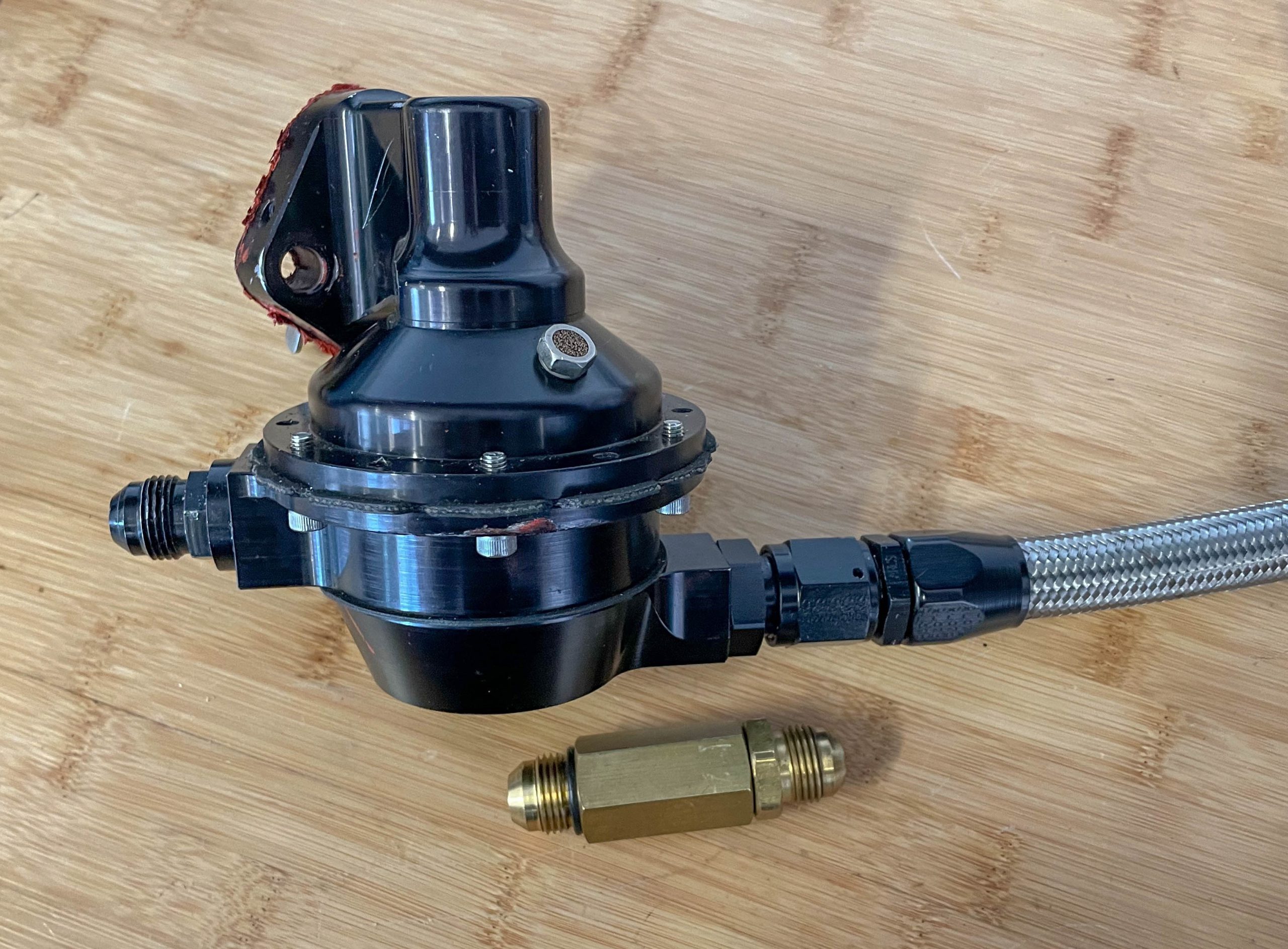
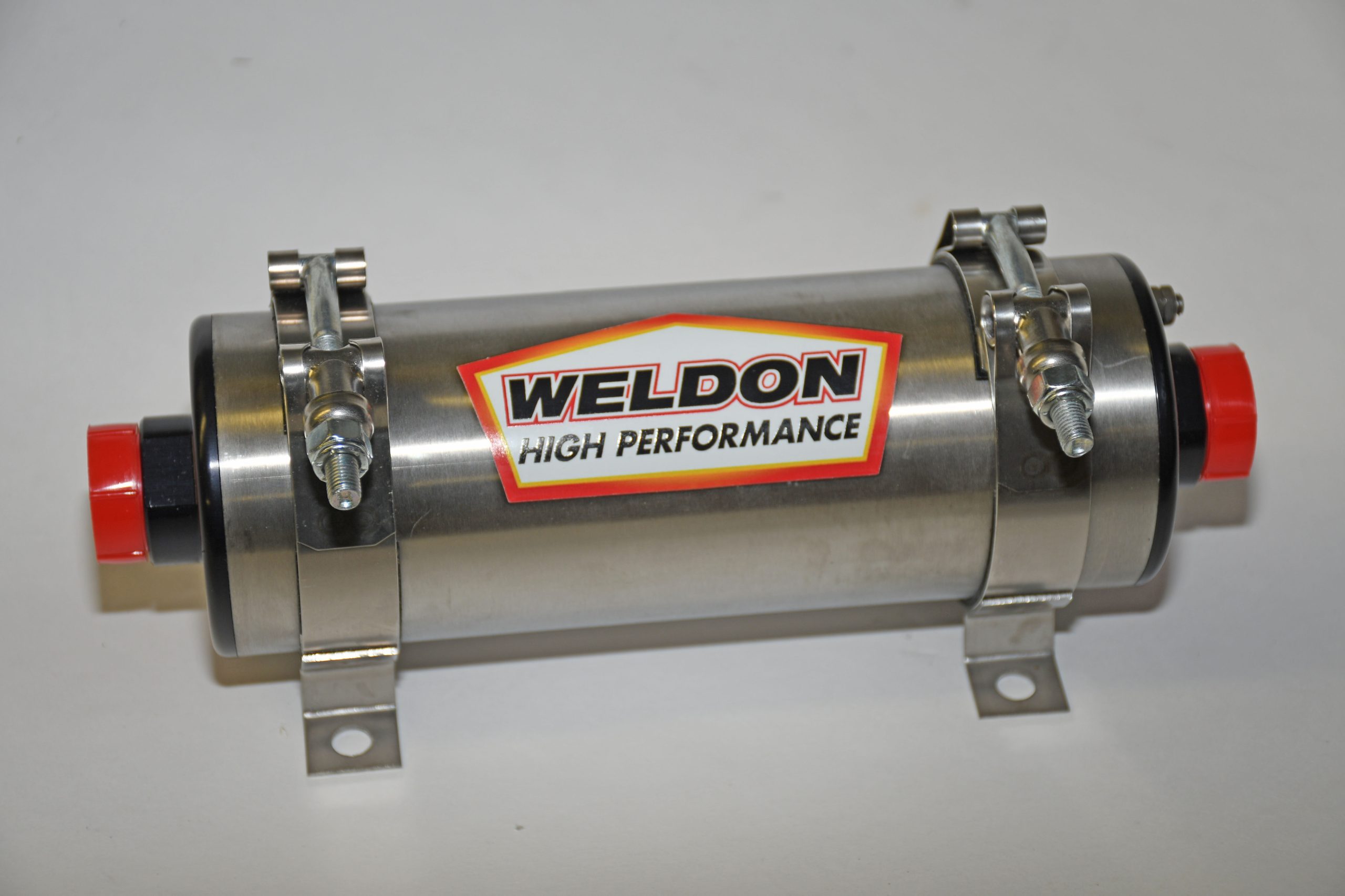
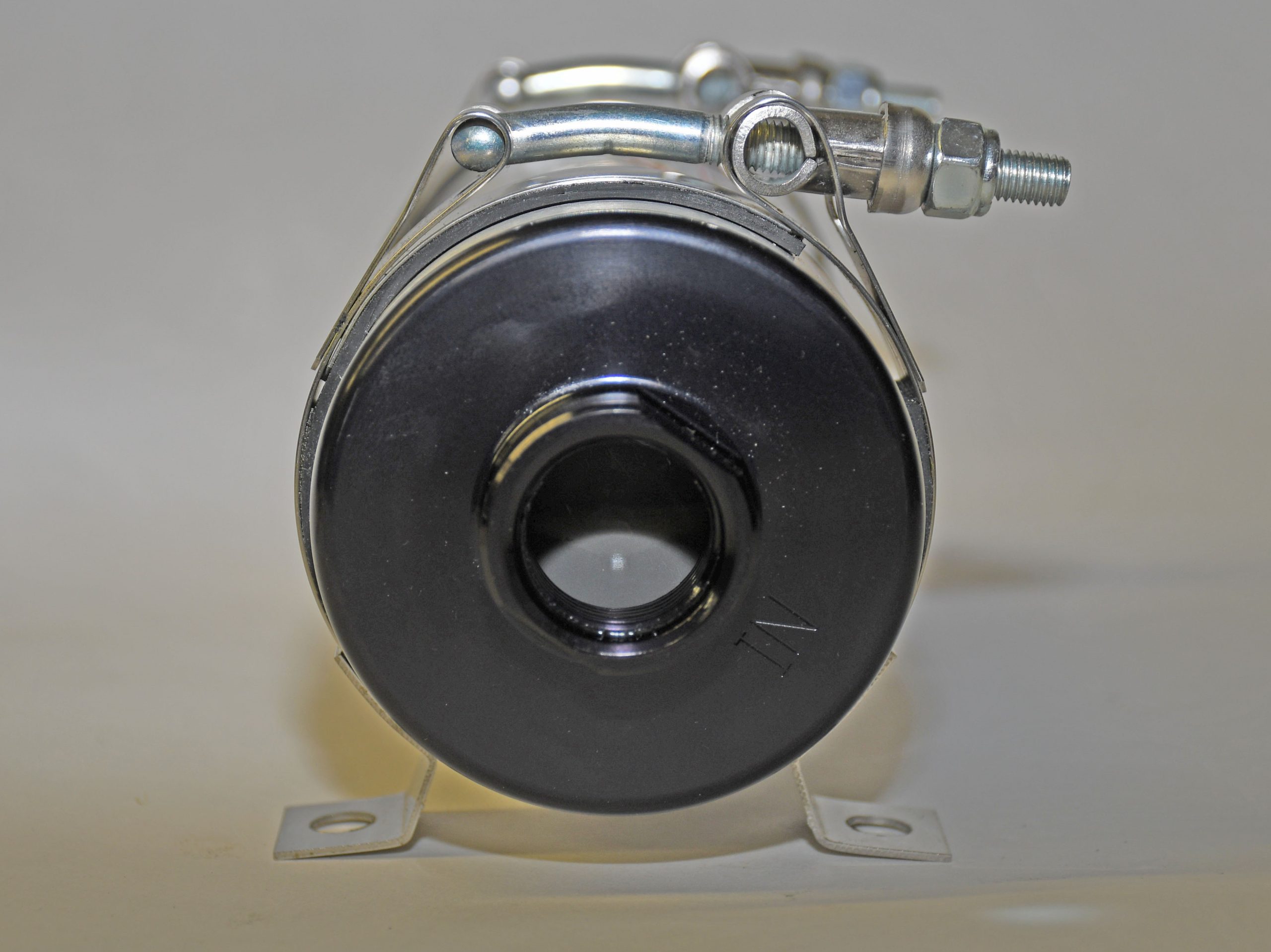
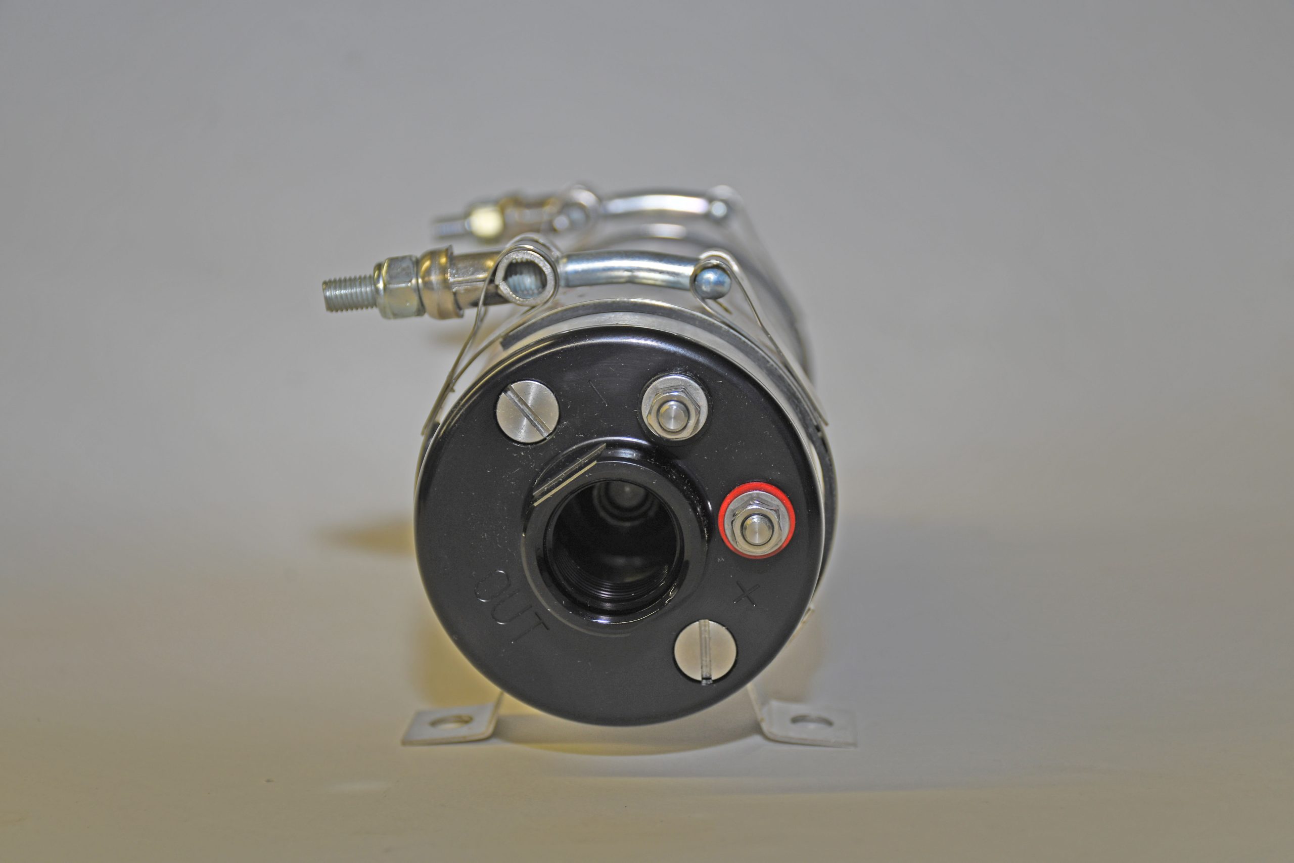
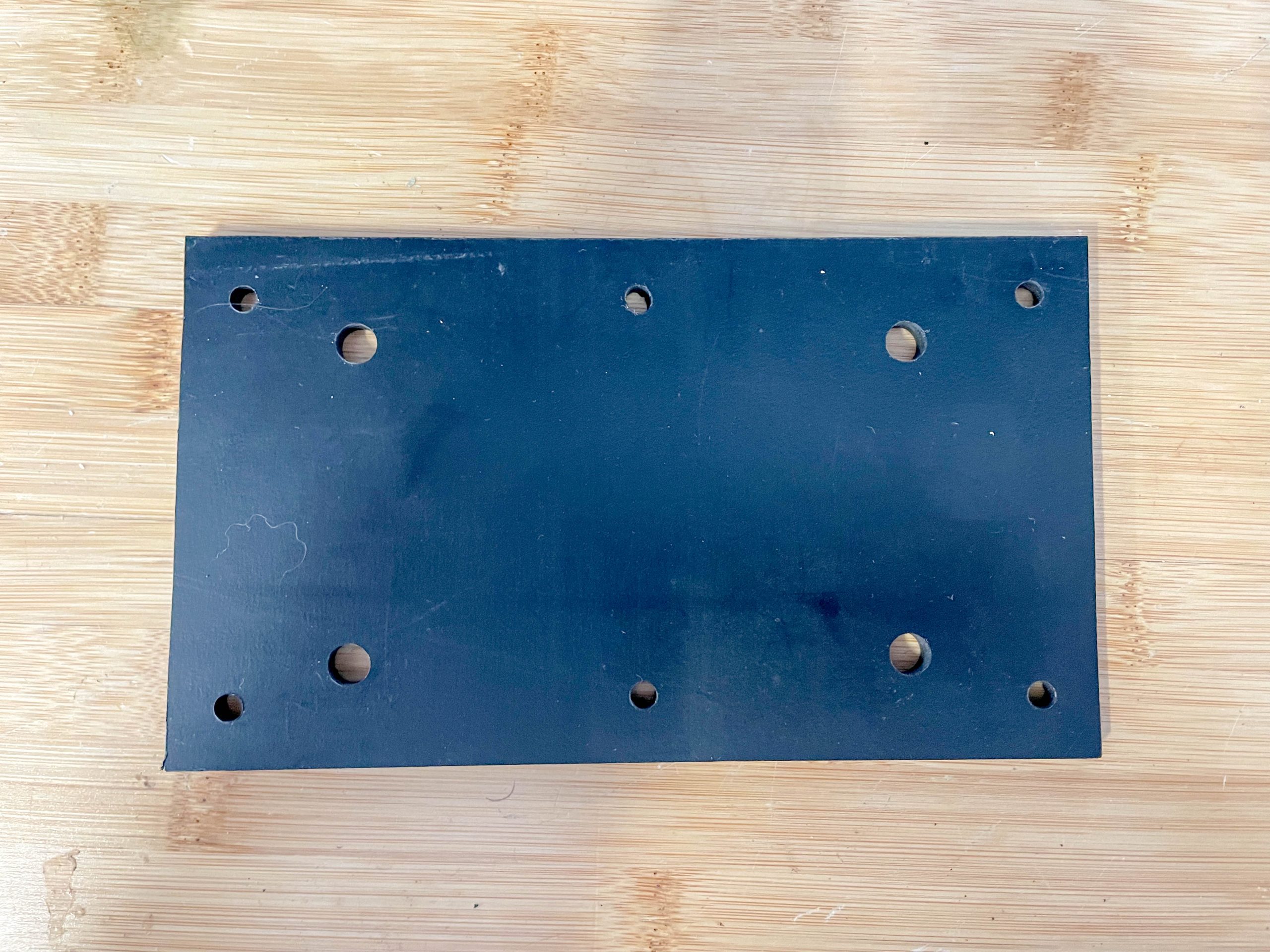
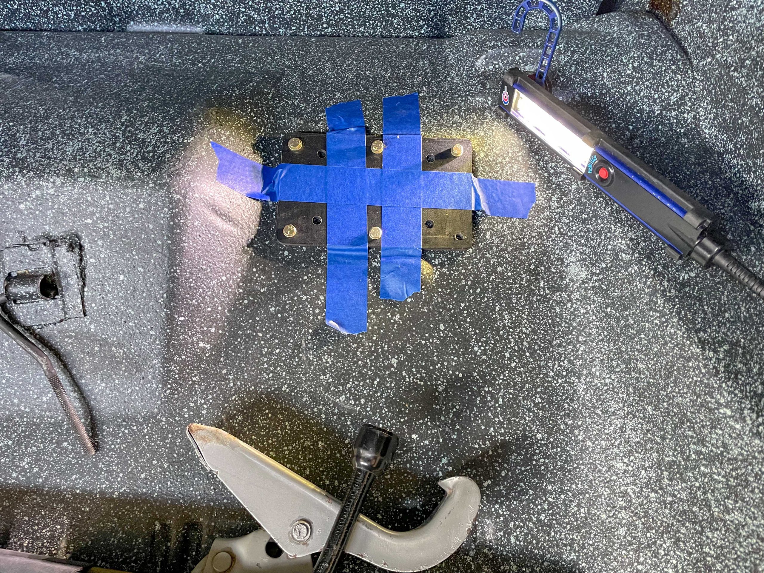
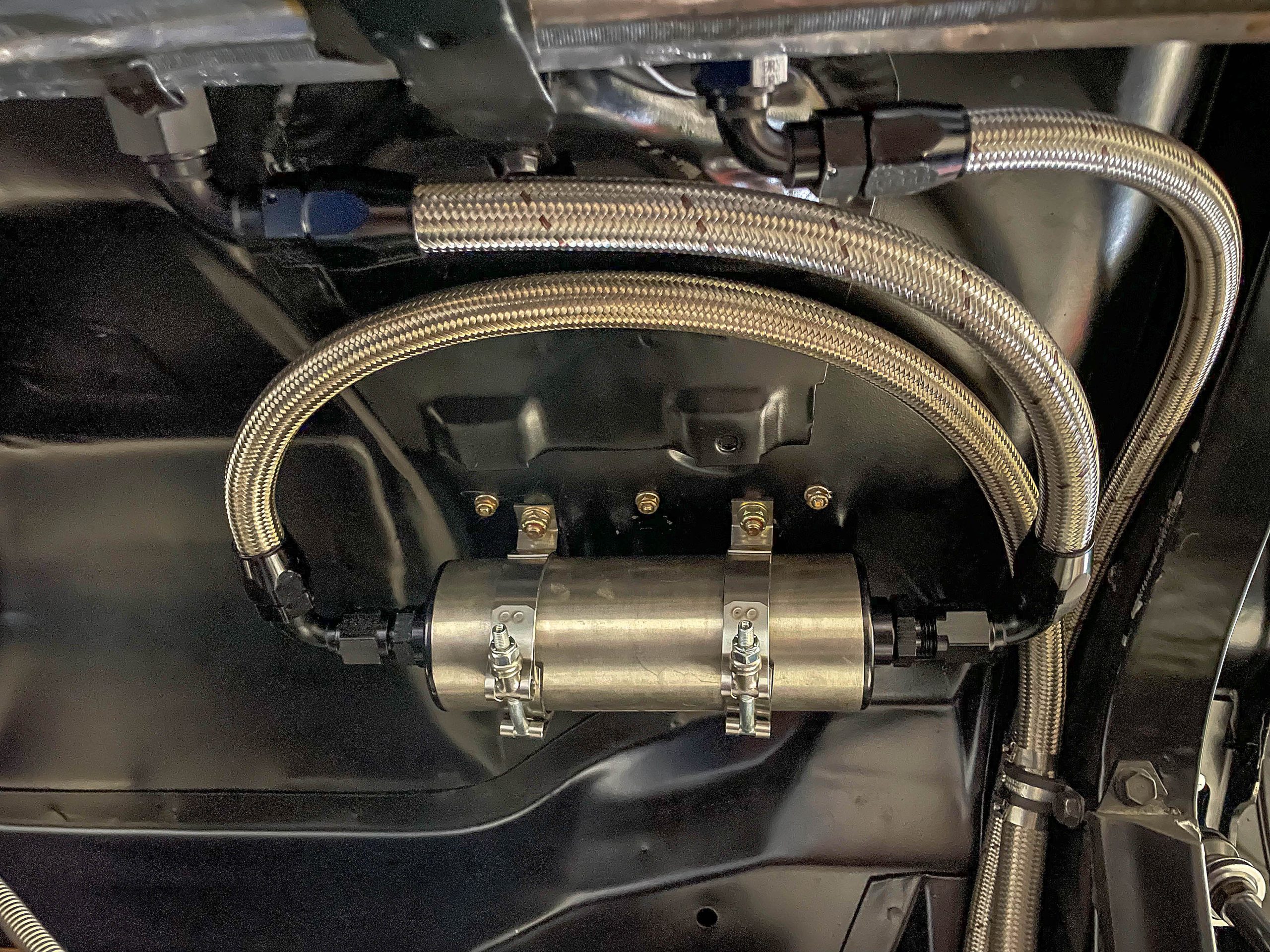
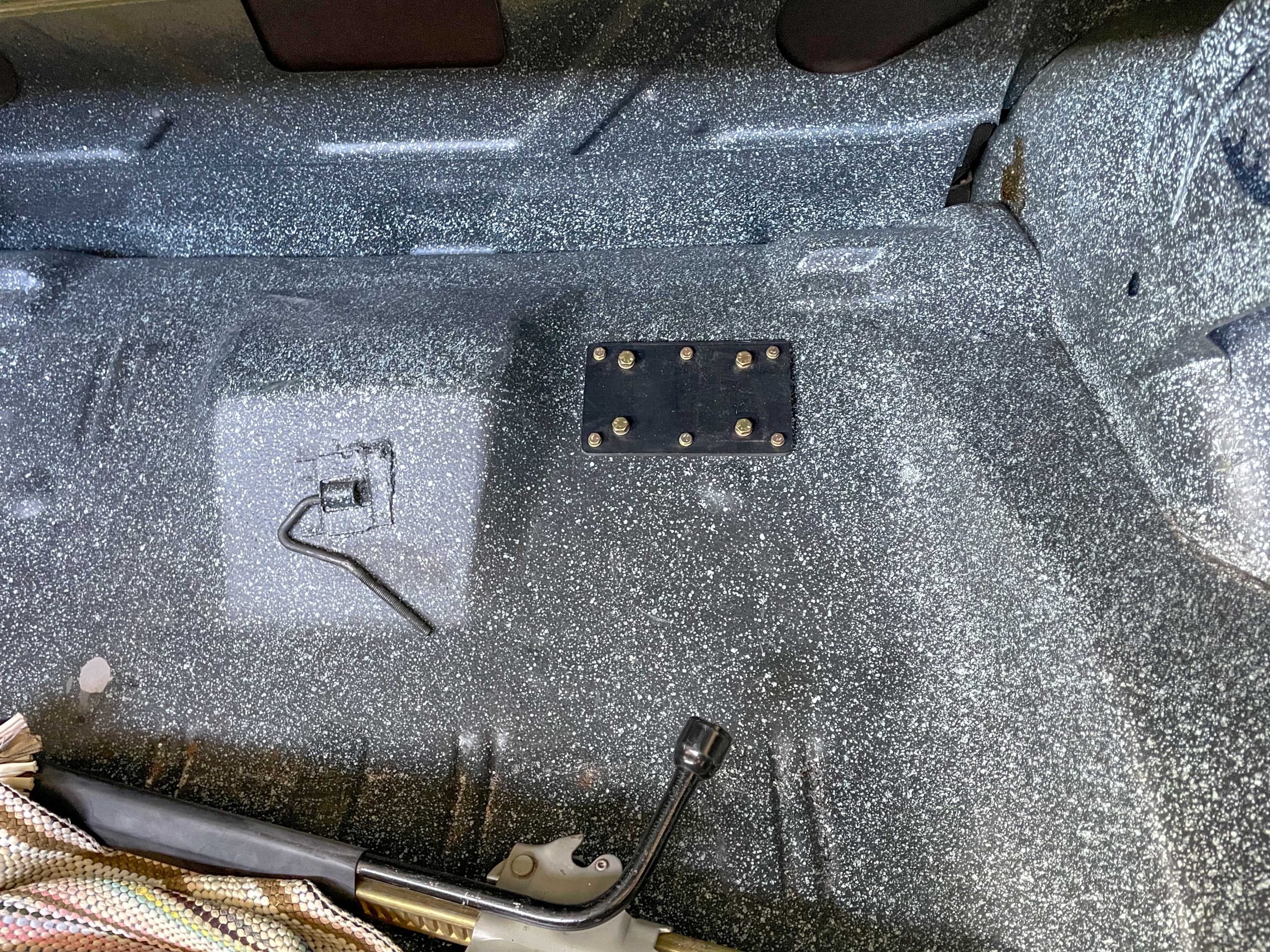
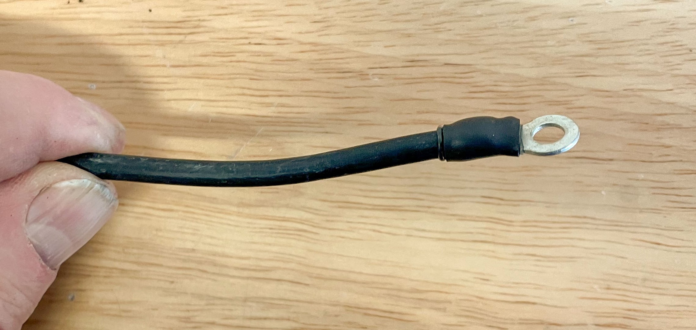
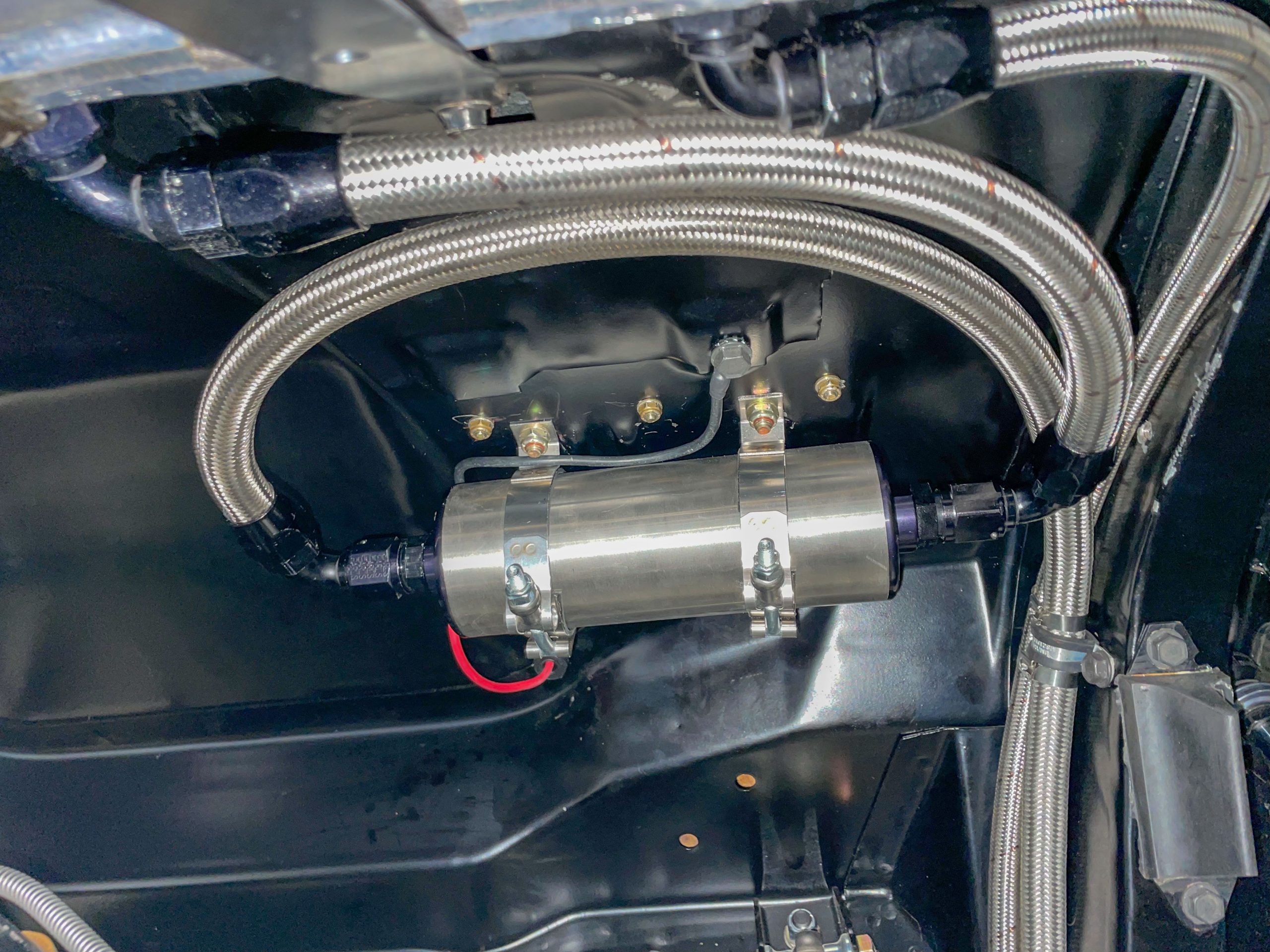
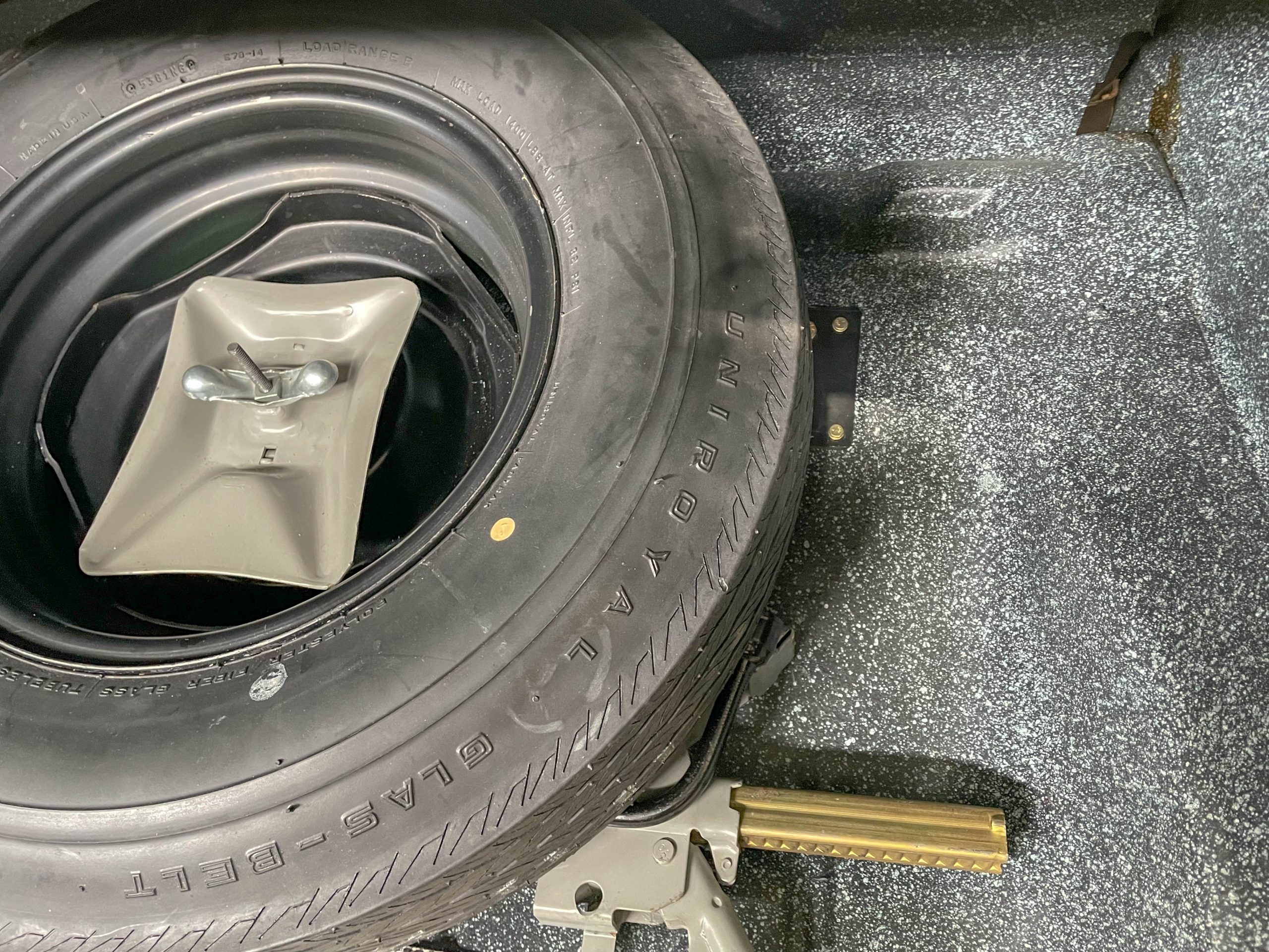
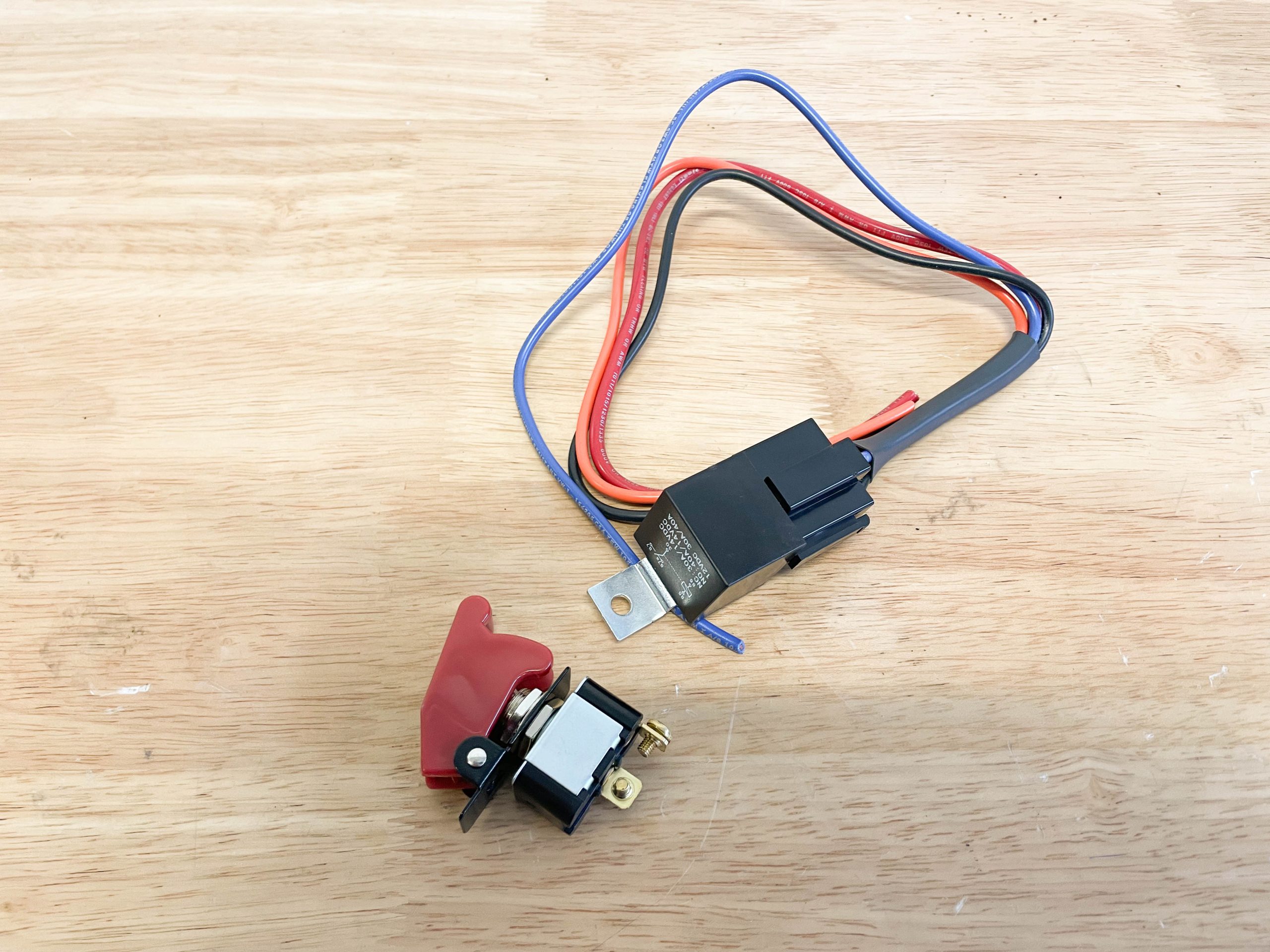
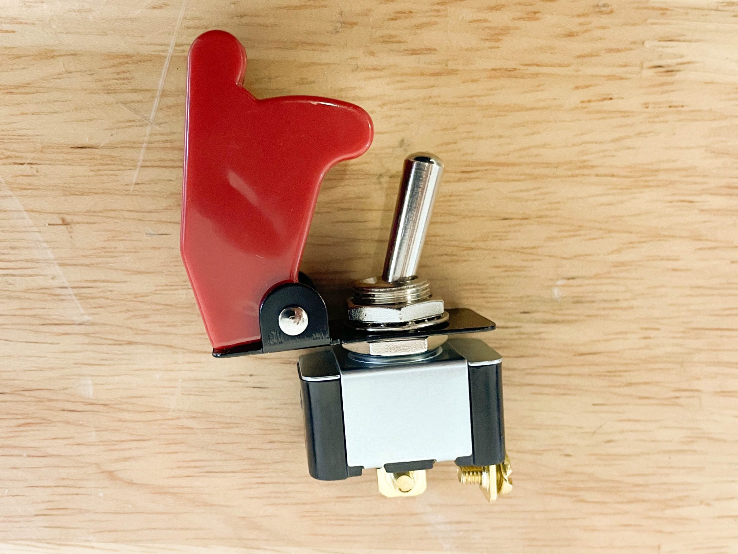
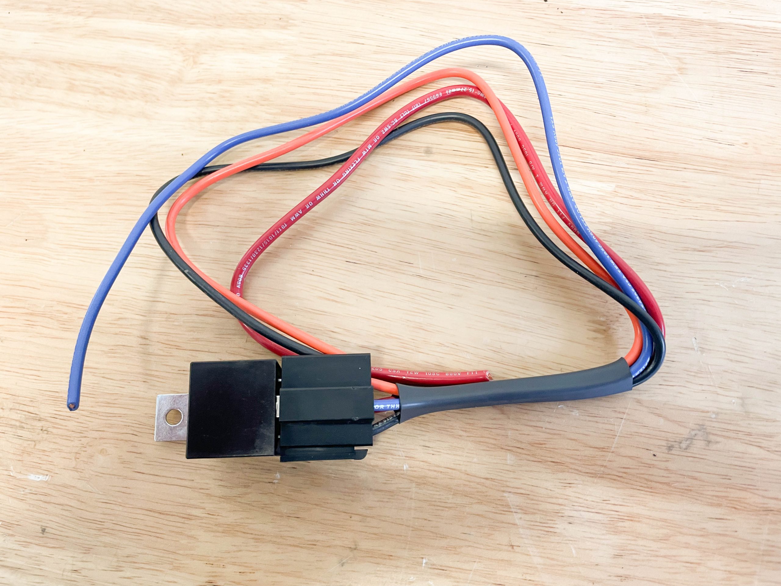
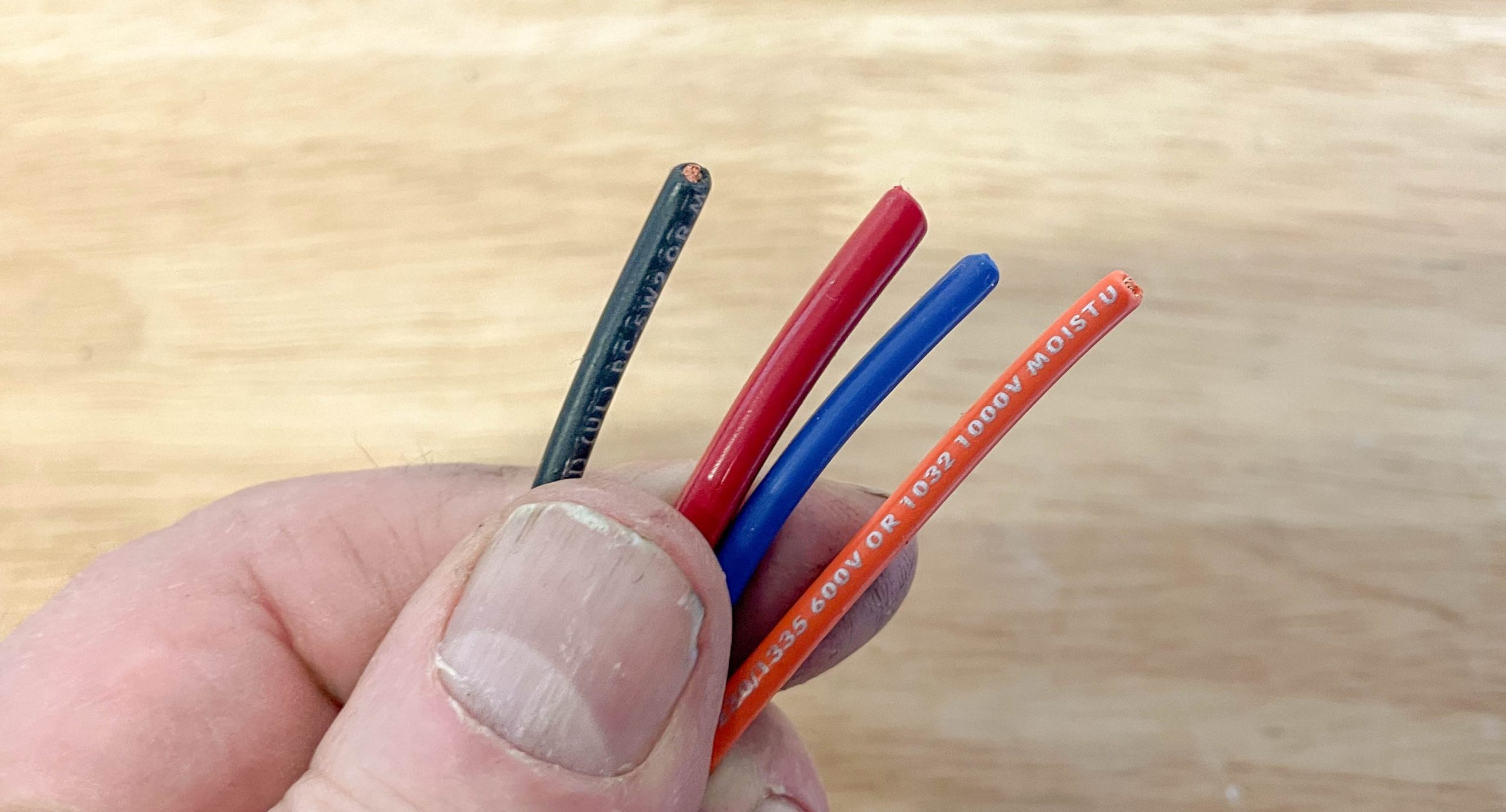
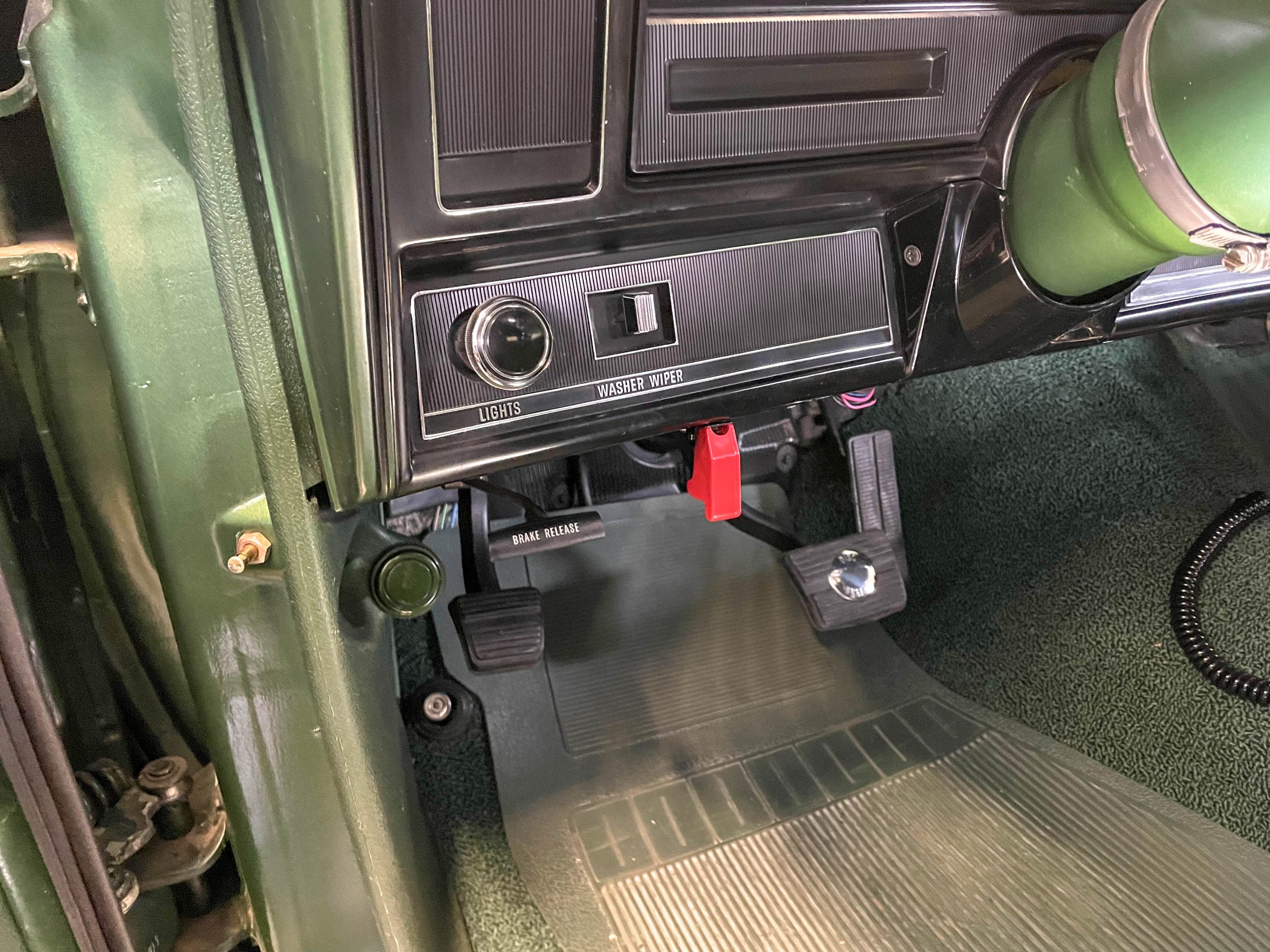
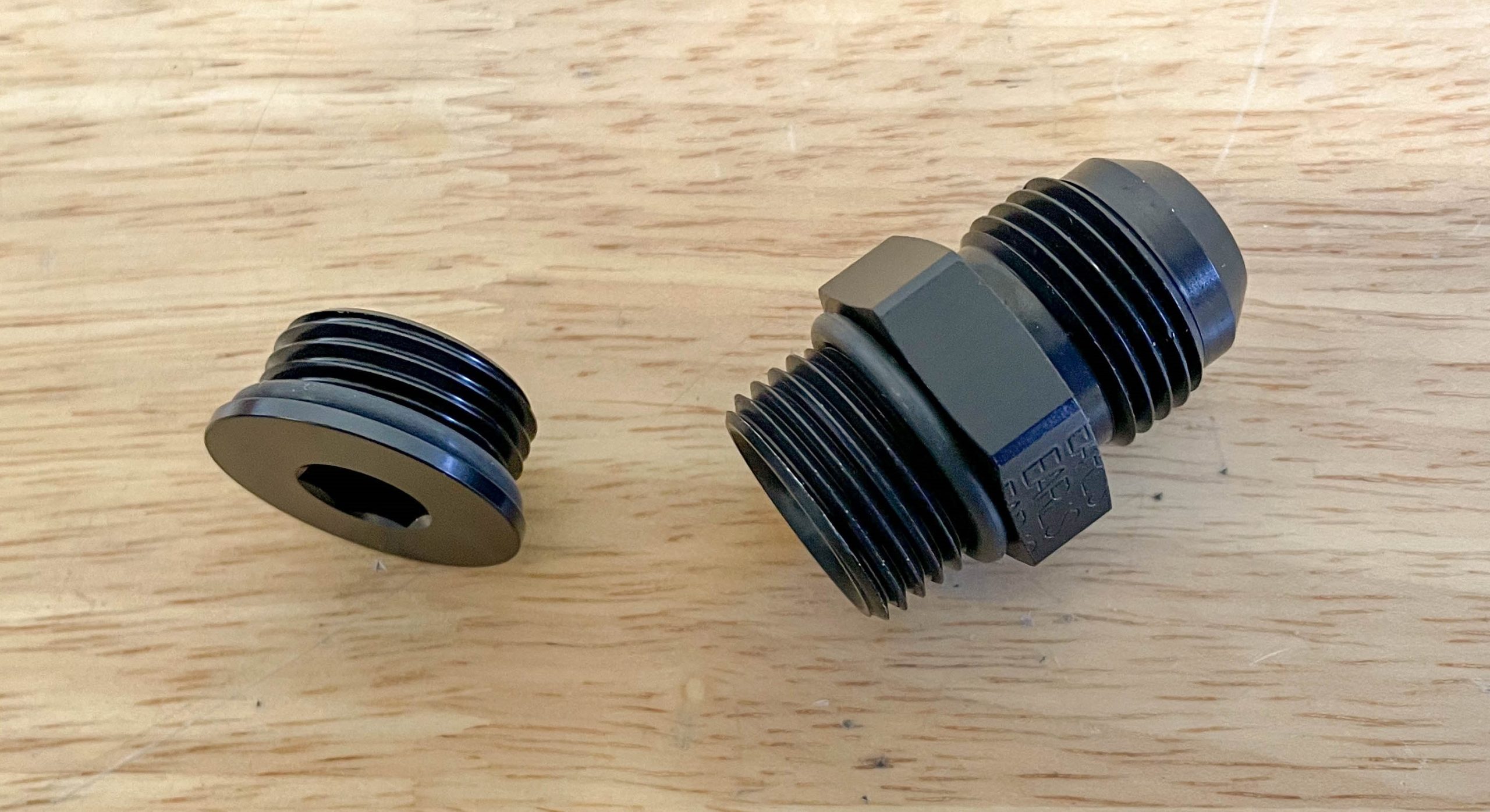
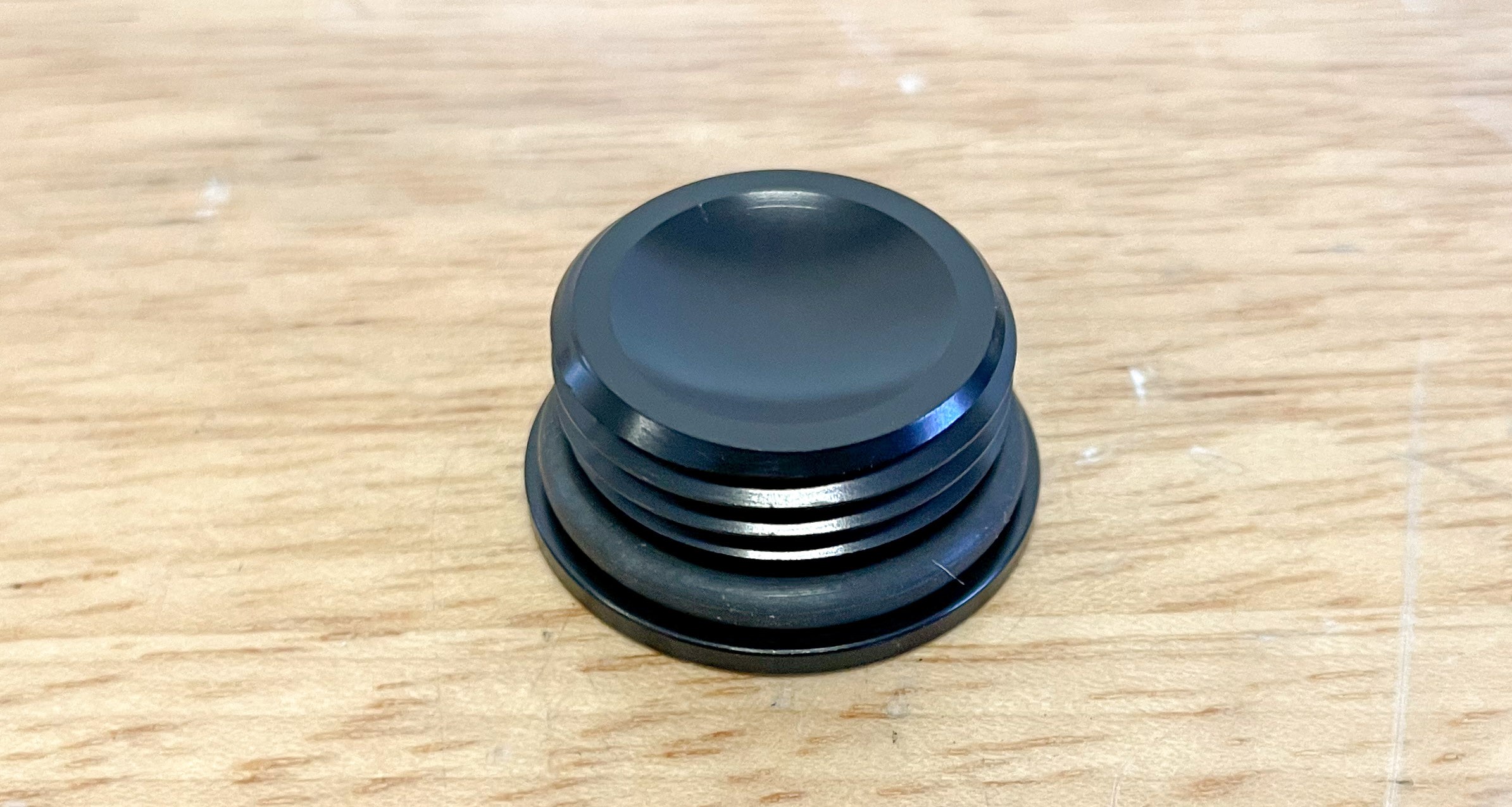
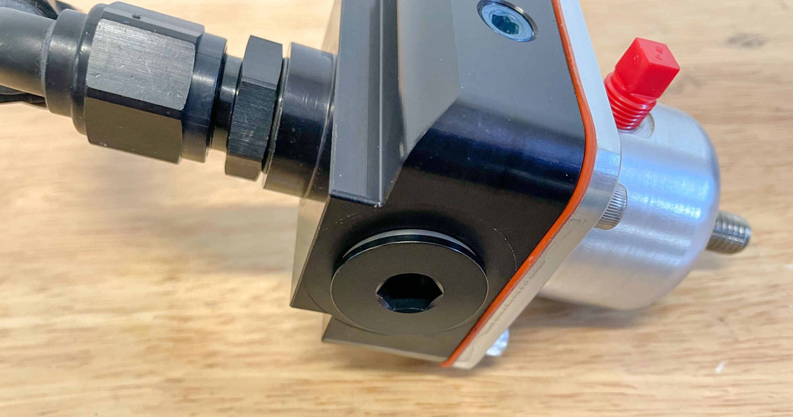
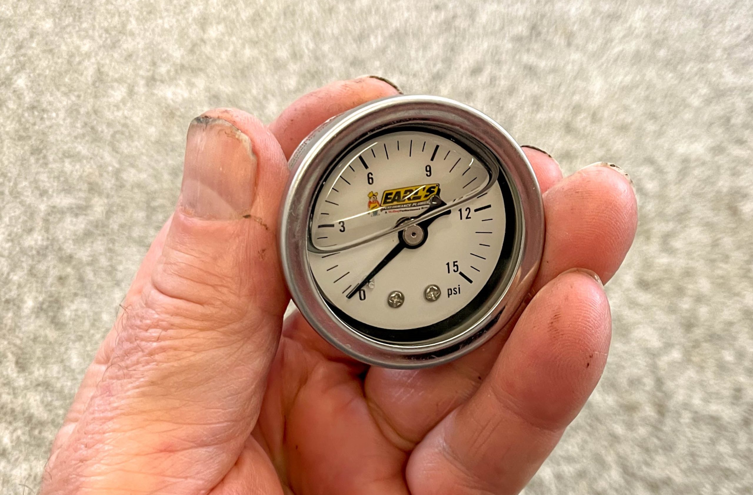
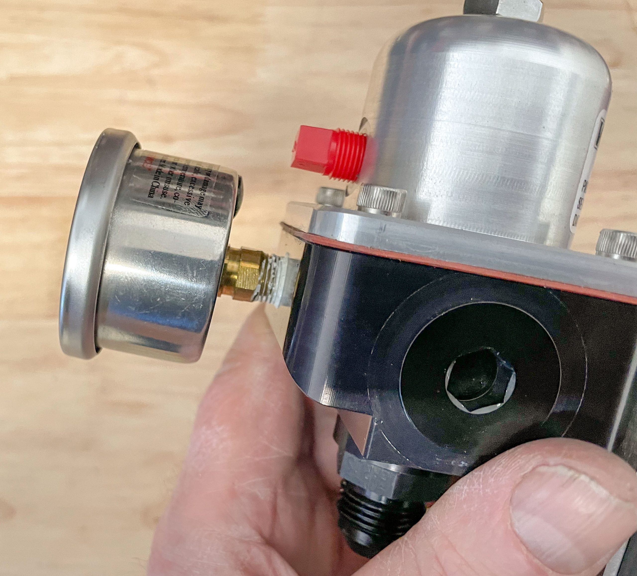
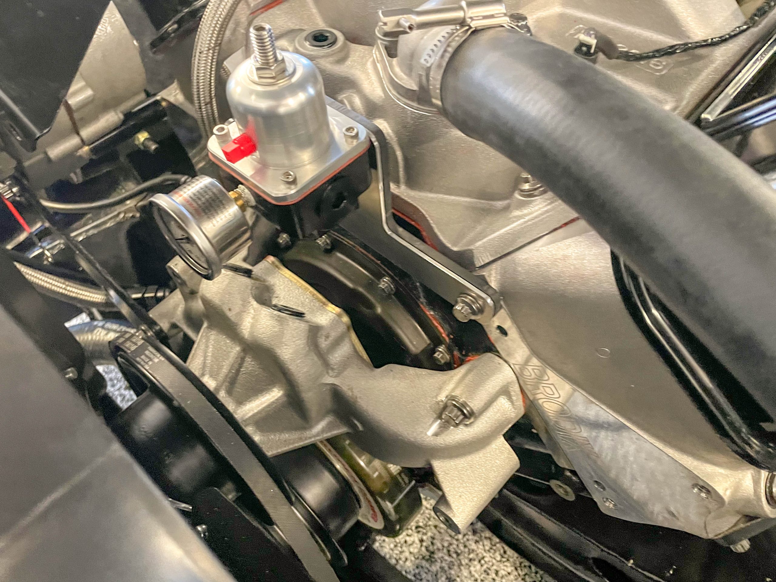
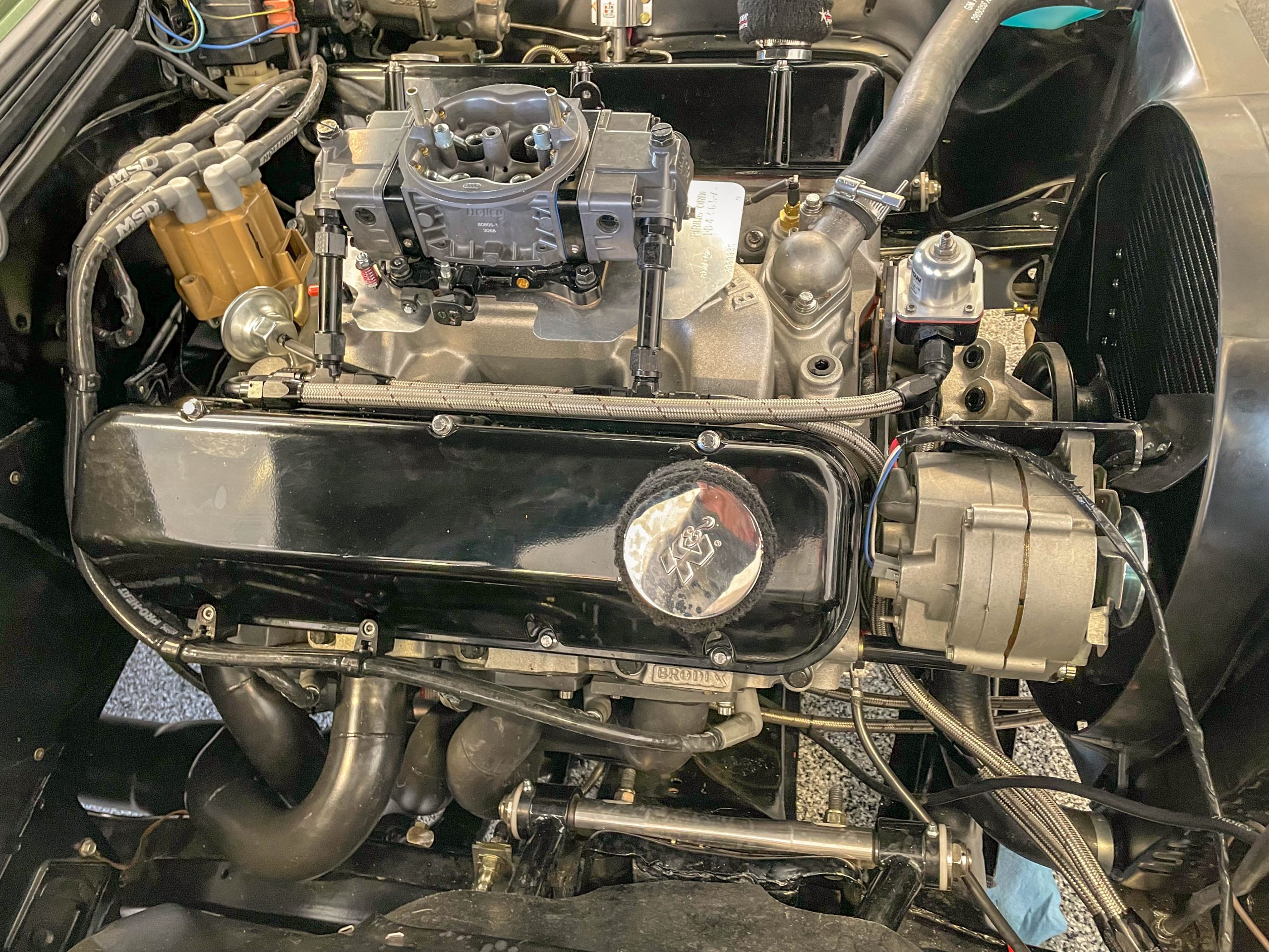
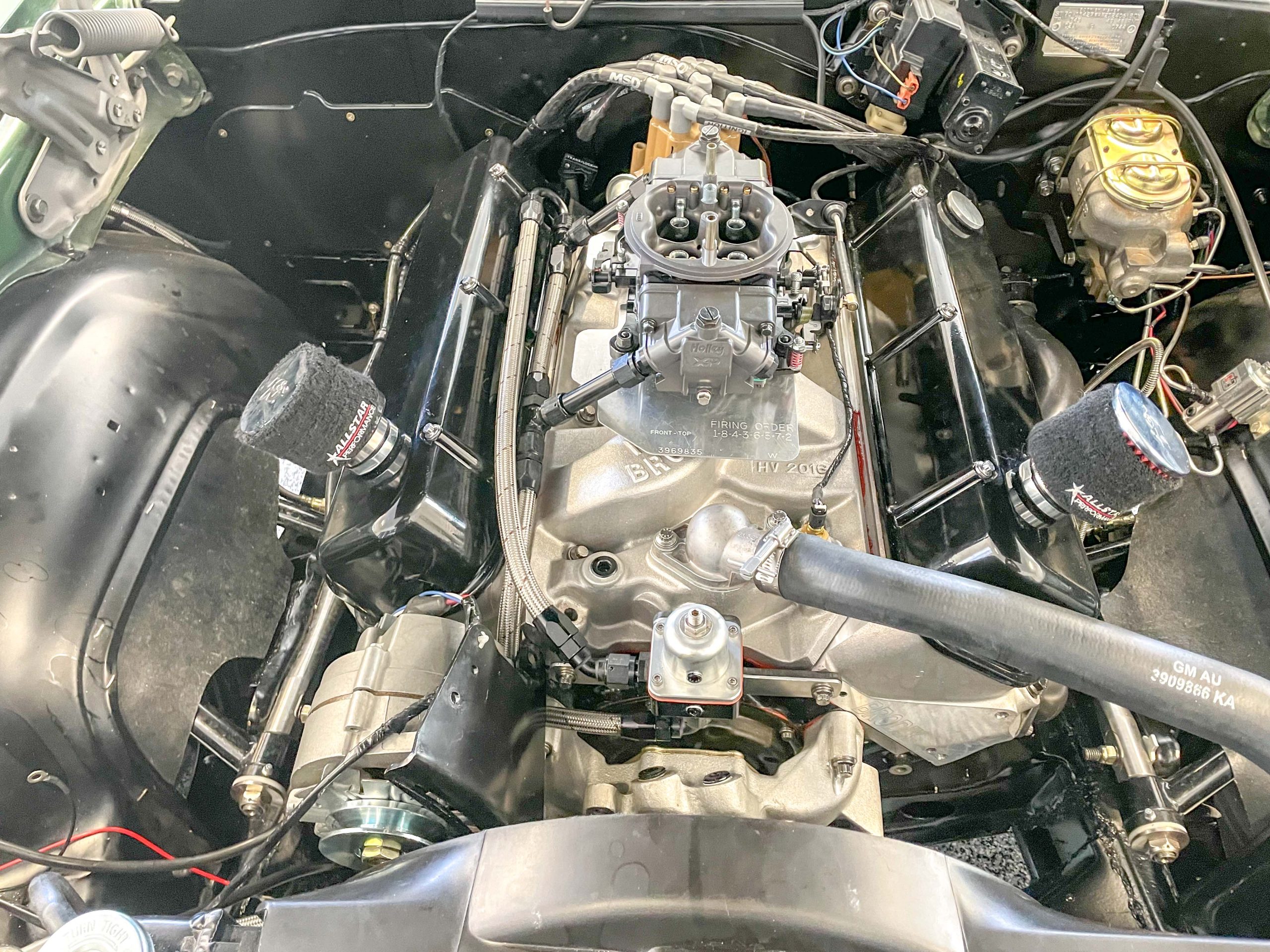
This was the original system: A marine Holley mechanical fuel pump regulated by way of a mechanical fuel injection bypass valve. In theory, it should work, but in practice, it brought along some issues, at least for me. This, coupled with the concern about pushrod failure (with a billet cam core) prompted the swap. (Image/Wayne Scraba)My electric pump of choice is a Weldon, and you can get a good look at it here. (Image/Wayne Scraba)The Weldon pump is set up for O-ring fittings on both the inlet (shown) and the outlet. Both the inlet and outlet are clearly marked. A big advantage of the Weldon pump is that it can physically pull a prime (not all electric pumps can accomplish that). This means it does not have to be mounted below the fuel level in the gas tank. (Image/Wayne Scraba)The electrical connections are on the outlet side and dirt simple. The red post is obviously the positive, while the black post is the negative. (Image/Wayne Scraba)The T-bolt band clamp mount brackets make for an easy installation. The Weldon pump comes with a pair of insulated mount clamps. (Image/Wayne Scraba)Any time something relatively heavy is bolted to a big expanse of sheet metal, it’s not a bad idea to use a doubler for reinforcement. Pumps aren’t that heavy, but once you add fuel to the mix, plus a bunch of hose, fittings, and so on, the stress and vibration may be too much for a single panel of sheet metal. Doublers like this (made from a sheet of machinable nylon) are easy to build. You can make them from aluminum too. (Image/Wayne Scraba)This is the location I selected for the pump mount. In this case, there really weren’t a lot of options when it came to finding a relatively flat mounting spot (flat on both top and bottom) that was away from moving parts and exhaust under the car. (Image/Wayne Scraba)Here’s the pump mounted and plumbed under the car. The system uses a -10 AN feed and pressure line along with a -8 AN return (from the regulator). There’s a bit of camera distortion here. I couldn’t plumb the pump directly from the bung on the tank to the inlet feed line, hence this layout. The reason it couldn’t be done is because of minimum bend radius of AN hose. Bend it too tight and it will kink—and consequently be turned into junk. (Image/Wayne Scraba)Topside, this is the completed doubler plate. The nylon plate seems to dampen pump noise, so it’s an added bonus, particularly for a street car. (Image/Wayne Scraba)Next up was wiring. For a ground, I used a 10 gauge wire as shown here. Once the terminal is crimped, I normally heat shrink the end. (Image/Wayne Scraba)This is the completed wiring job at the pump. As mentioned previously, wiring an electric fuel pump isn’t difficult. (Image/Wayne Scraba)With the spare tire installed, most of the doubler is covered. Ditto with covering most of the wiring inside the trunk. (Image/Wayne Scraba)You’ll need a good quality switch and in many cases, a relay to operate the pump. (Image/Wayne Scraba)My switch of choice is this heavy duty aircraft style one from Quick Car Racing products (part number QCR-50-520). Aside from the safety flip up cover, the switch has a hefty 25 amp rating, features a steel and plastic body, and uses screw-style terminals. (Image/Wayne Scraba)Depending upon the pump, you might need a relay. This pre-wired single relay from MagnaFuel (part number MP-1025) has a 30 amp rating. (Image/Wayne Scraba)When it comes to wiring the relay, the heavy black wire goes to ground. The heavy red wire goes to the battery. The orange wire is routed to the on/off switch (or the vehicle ignition switch). The blue wire goes to the hot side of the electric pump—where, in my case, I typically use a red wire. (Image/Wayne Scraba)Here’s the switch installed in the car. It needs a half inch or larger hole for the post to pass through. In addition, the flip cover makes it easy to turn the switch off in an emergency. (Image/Wayne Scraba)This was mentioned previously, but the Weldon components (pump and regulator) are engineered for use with O-ring fittings. These fittings are from Earl’s Performance. Fitting sizes and format are obviously different from pump manufacturer to manufacturer. (Image/Wayne Scraba)O-ring fittings are pretty much bulletproof. Earl’s offers packs of replacement O-rings (if necessary). The only time you might encounter a leak is if the fitting is over or under-tightened. (Image/Wayne Scraba)One port is plugged in my setup. As you can see, the O-ring isn’t squashed. What’s with the red fitting on the top of the regulator? It’s just a plug Weldon uses for shipping. The port where it is attached is for boost reference. Since this car is naturally aspirated, I don’t need to use the boost reference port. It can be left open or plugged. (Image/Wayne Scraba)In order to setup the regulator, you’ll need a fuel pressure gauge. This is a liquid filled Earl’s model. (Image/Wayne Scraba)Typically, I use these little gauges for setup only and once that’s done, I remove them and plug the port. Alternatively, you can use the port to hook up a conventional large fuel pressure gauge, which is something I might do down the road. (Image/Wayne Scraba)You’ll have to mount the regulator somewhere. They can be on an inner fender well or on the engine. Some folks don’t like engine mounts for fear of vibration messing up the regulator (but many OEM regulators are engine-mounted). On a similar note, for some applications (and some regulators), you can purchase a regulator mounting bracket from Summit Racing to put the regulator right next to the carburetor. With the bypass plumbing setup I’m using, that wasn’t possible. As a result, I made up this regulator bracket that mounts to the cylinder heads. It was fabbed from aluminum with a nylon backing plate for reinforcement. (Image/Wayne Scraba)This is the finished plumbing job at the carburetor. (Image/Wayne Scraba) How it works is the pressure line from the pump feeds the fuel line directly. Pressure is regulated after the carburetor. Excess fuel is returned to the tank by way of the lower -8 AN line at the bottom of the regulator. If you have a dead-head system (without a return), your plumbing will differ. (Image/Wayne Scraba)
Wayne Scraba is a diehard car guy and regular contributor to OnAllCylinders. He’s owned his own speed shop, built race cars, street rods, and custom motorcycles, and restored muscle cars. He’s authored five how-to books and written over 4,500 tech articles that have appeared in sixty different high performance automotive, motorcycle and aviation magazines worldwide.
Comments
7 responses to “How To Switch From A Mechanical Fuel Pump To An Electric One”
When I went to carb from fuel injection I had to use a larger 1/ 2 “ return line from the pressure reg back to the tank on my 302 ff5 cobra to be able to adjust the fuel pressure down to 6 psi to my 600 Holley using the stock in tank electric fuel pump. Also had to go to a Davis distributor. Love the sound and smell of a old school carburetor.
I have a 1986 Ford F-250 (used for towing heavy trailers, a work horse) stock setup. The OEM fuel regulator with bypass has gone bad and the fuel pump is now blowing the seals on the carb. The pump is the same as for the later models that had fuel injection. I understand it operates at around forty PSI. The regulator delivered fuel between 4-8 PSI to the carb. I can get several pressure regulators which will do the job to restrict the flow, however this constipates the pump, which may eventually cause failure. Do you know of a pressure switch that will just shut the pump off when it reaches full pressure? I think the on/off situation would likely be far less harmful to the pump than constantly running against a static pressure limit.
I know this isn’t something that adds to the fun factor, However it isn’t fun having a tow vehicle that is shut down by a two-inch flow restrictor with return which is no longer available.
I think there’s a typo in your question: Are you saying you currently have an in-tank pump and want to switch to an external?
Is there a specific reason you want to change to an external pump? Is it a stock application? From our experience, in-tank fuel pumps tend to stay cooler, last longer, and run quieter than an external pump. In addition, an in-tank fuel won’t run dry under hard acceleration. If you’ve got an issue with your stock in-tank pump, then it’s likely that the best solution is to simply replace your pump with a stock equivalent.
I have an electric pump on my 1957 Thunderbird because the Chinese mechanical pumps leak gas into the oil through the diaphragm that dissolves with modern gas. I also installed an inertia cutout switch to prevent gas from flowing over the hot engine in an accident. I’d rather not burn up.
When I went to carb from fuel injection I had to use a larger 1/ 2 “ return line from the pressure reg back to the tank on my 302 ff5 cobra to be able to adjust the fuel pressure down to 6 psi to my 600 Holley using the stock in tank electric fuel pump. Also had to go to a Davis distributor. Love the sound and smell of a old school carburetor.
I have a 1986 Ford F-250 (used for towing heavy trailers, a work horse) stock setup. The OEM fuel regulator with bypass has gone bad and the fuel pump is now blowing the seals on the carb. The pump is the same as for the later models that had fuel injection. I understand it operates at around forty PSI. The regulator delivered fuel between 4-8 PSI to the carb. I can get several pressure regulators which will do the job to restrict the flow, however this constipates the pump, which may eventually cause failure. Do you know of a pressure switch that will just shut the pump off when it reaches full pressure? I think the on/off situation would likely be far less harmful to the pump than constantly running against a static pressure limit.
I know this isn’t something that adds to the fun factor, However it isn’t fun having a tow vehicle that is shut down by a two-inch flow restrictor with return which is no longer available.
Hey Ron, click here to contact the Summit Racing tech folks. They might be able to source some sort of pump/regulator combo that can solve your issue.
I have a fuel pump inline and I’m wondering if I can change it to a inline electric pump. How would I disconnect the Internet tank pump
I think there’s a typo in your question: Are you saying you currently have an in-tank pump and want to switch to an external?
Is there a specific reason you want to change to an external pump? Is it a stock application? From our experience, in-tank fuel pumps tend to stay cooler, last longer, and run quieter than an external pump. In addition, an in-tank fuel won’t run dry under hard acceleration. If you’ve got an issue with your stock in-tank pump, then it’s likely that the best solution is to simply replace your pump with a stock equivalent.
I have a Holley 12-312 fuel pump that I want to use with a carburetor.what will I need to make this work
I have an electric pump on my 1957 Thunderbird because the Chinese mechanical pumps leak gas into the oil through the diaphragm that dissolves with modern gas. I also installed an inertia cutout switch to prevent gas from flowing over the hot engine in an accident. I’d rather not burn up.