This Mustang is SpecFab Racing’s championship winning test bed for race products. (Image/Christopher Campbell)
Everyone loves easy power plays, especially the ones that offer noticeable returns for little effort and investment. The right tricks can even make more power to wheels without actually the engine actually making more power. The key is reducing parasitic losses.
By reducing the parasitic losses on the engine, more of the power that it’s already making gets to the wheels. Our project car for this miniseries of articles is a 2005 Mustang GT that is mostly used for time attack and high performance driving events (HPDE). However, it’s also a street car registered in California, so it needs to stay emissions legal—mostly because we want to drive it to and from the track. Forced induction and the weight and increased heat it brings are out of the question. That means we’re pretty limited on our power increasing options, so it’s time look for the gremlins eating the power we already have.
Anything the engine turns costs horsepower. While running around on the street at lower RPM, these stolen numbers are usually pretty modest, meaning that you may not notice these losses at low RPM. However, the faster the engine spins, such as when it’s running on a road course or drag strip, the more horsepower each component requires. This is when single digit power losses turn into double digit losses. With that in mind, while looking at the front of the engine we’re presented with a few options. We’re going to start by going straight for the obvious—the water pump.
We know what you’re thinking, “electric water pump on a track car?” Yes, hear us out on this one. Meziere’s WP346 high flow pump for modular Ford engines is designed for street or drag strip use and is rated for a constant 55 gallons per min (GPM) free flow. For reference, most mechanical water pumps for V8 engine applications flow in the vicinity of eight gallons per minute at idle, and around 70 gallons per minute at 6,500 rpm. That trade-off costs about 12 horsepower to the wheels.
At idle and low rpm, like stop and go traffic, the Meziere pump will typically flow two to three times as much as a mechanical pump. However, once the engine rpm exceeds 3,000, the pendulum swings in favor of mechanical pumps. Above 6,500 rpm, there’s really no contest when it comes to maximum flow. But the question is, “do you actually need that level of flow?” We think not for our naturally aspirated project.
To check our thought process, we reached out to Meziere. They told us they saw no potential issues with a healthy or upgraded cooling system on street driven track day car running limited sessions. They did add that they would not recommend this water pump for extended high RPM endurance style racing, but it should be more than adequate for our flat-out 20 minute track sessions.
But you don’t have to believe us or even Meziere; our friend Sal Molinare of SpecFab Racing has proven that it can work for years with his trusty Frankenstang.
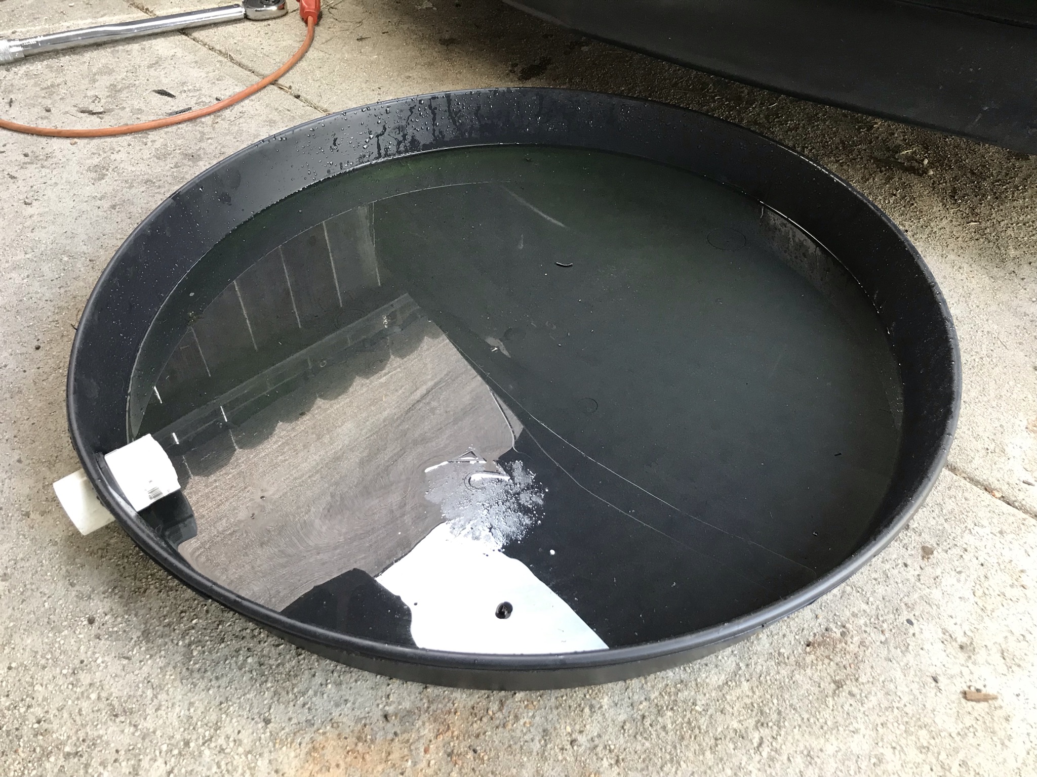
Sal ran the same Meziere pump in Frankenstang during its evolution from daily driver, to drag car, and then championship winning road race car for over nine years. Through each of those versions, the stroked 3V was twin screw supercharged and making near 700 hp to the wheels. Sal swears he never experienced a failure or even fought overheating issues. He recently swapped to a Coyote engine and put a Meziere pump on it as well. Plus, as Sal said, “When you consider what some other mods cost to develop 12 horsepower, it’s really not what I would call expensive.” We were sold on this experiment after chatting with him.
Oh yeah, one more thing about this project. Ford modular engines have a secret that makes an electric water pump a super easy upgrade; you can swap one on in about 20 minutes, so it’s not even a huge time commitment if your needs change and you decide to swap back to a mechanical pump. And you don’t even have to drain the coolant. It’s true, we did it. We also took our project one step further and upgraded to the 2007-10 style cooling system for the best results. Read on and we’ll show you how.
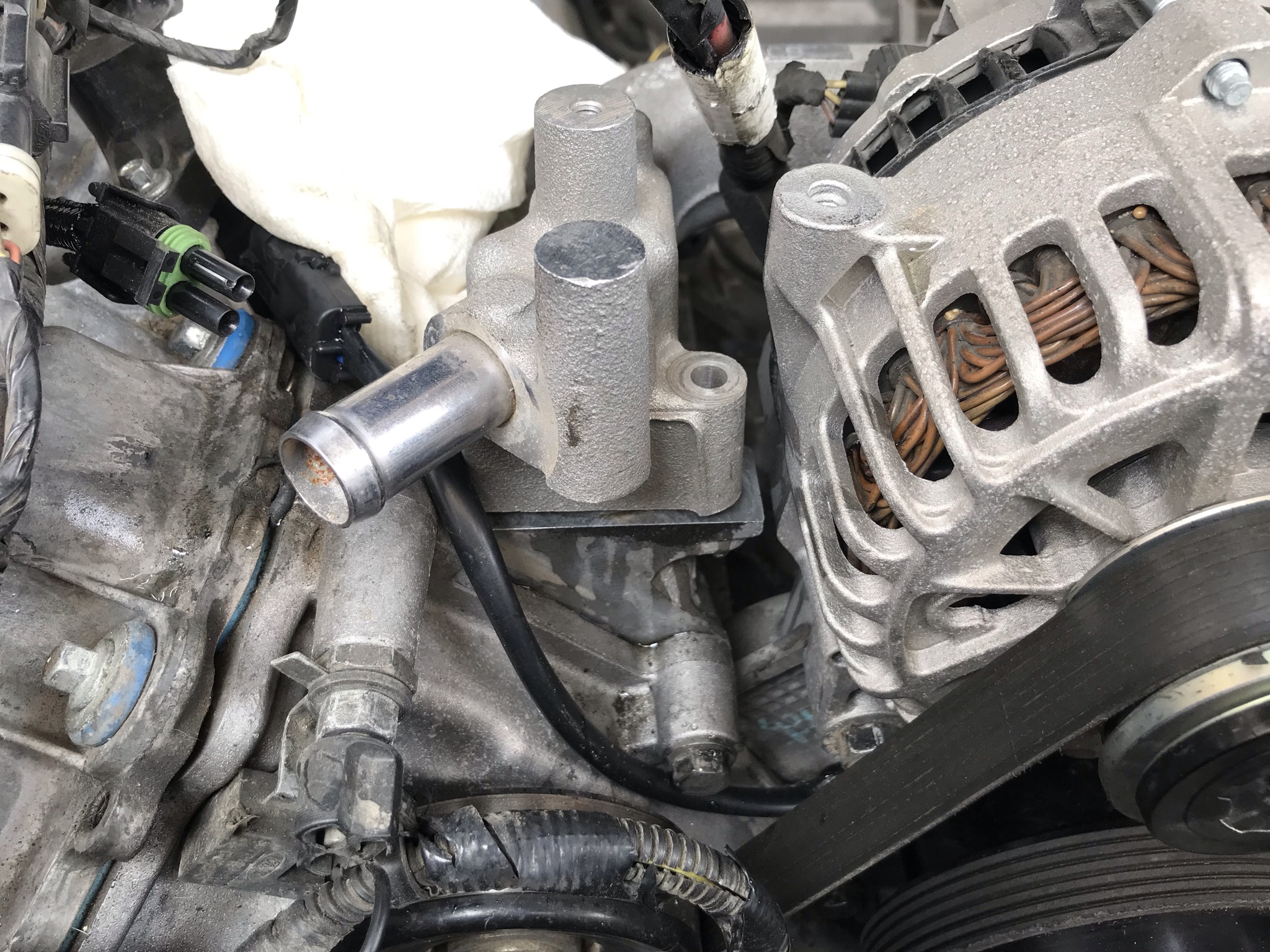
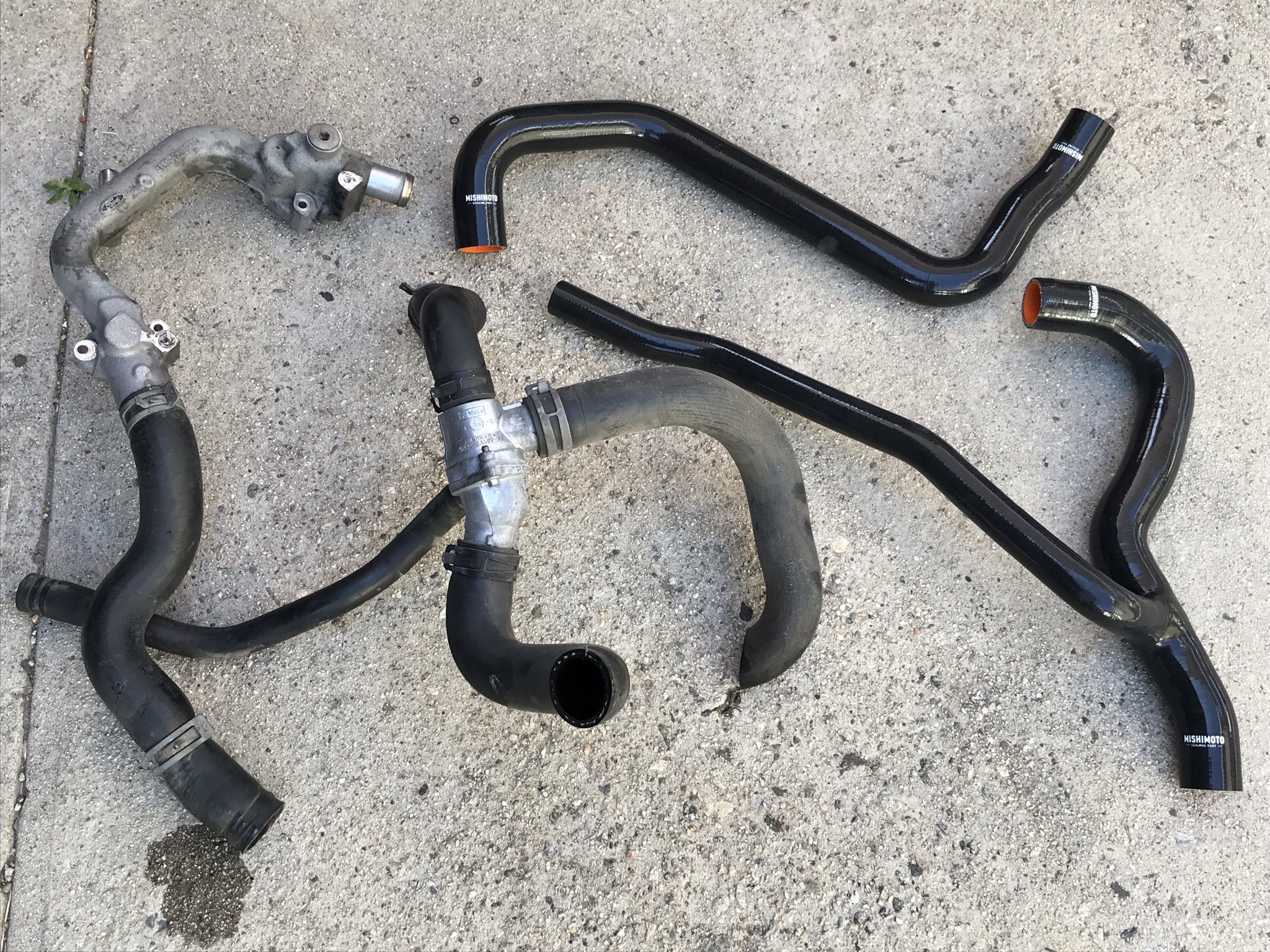
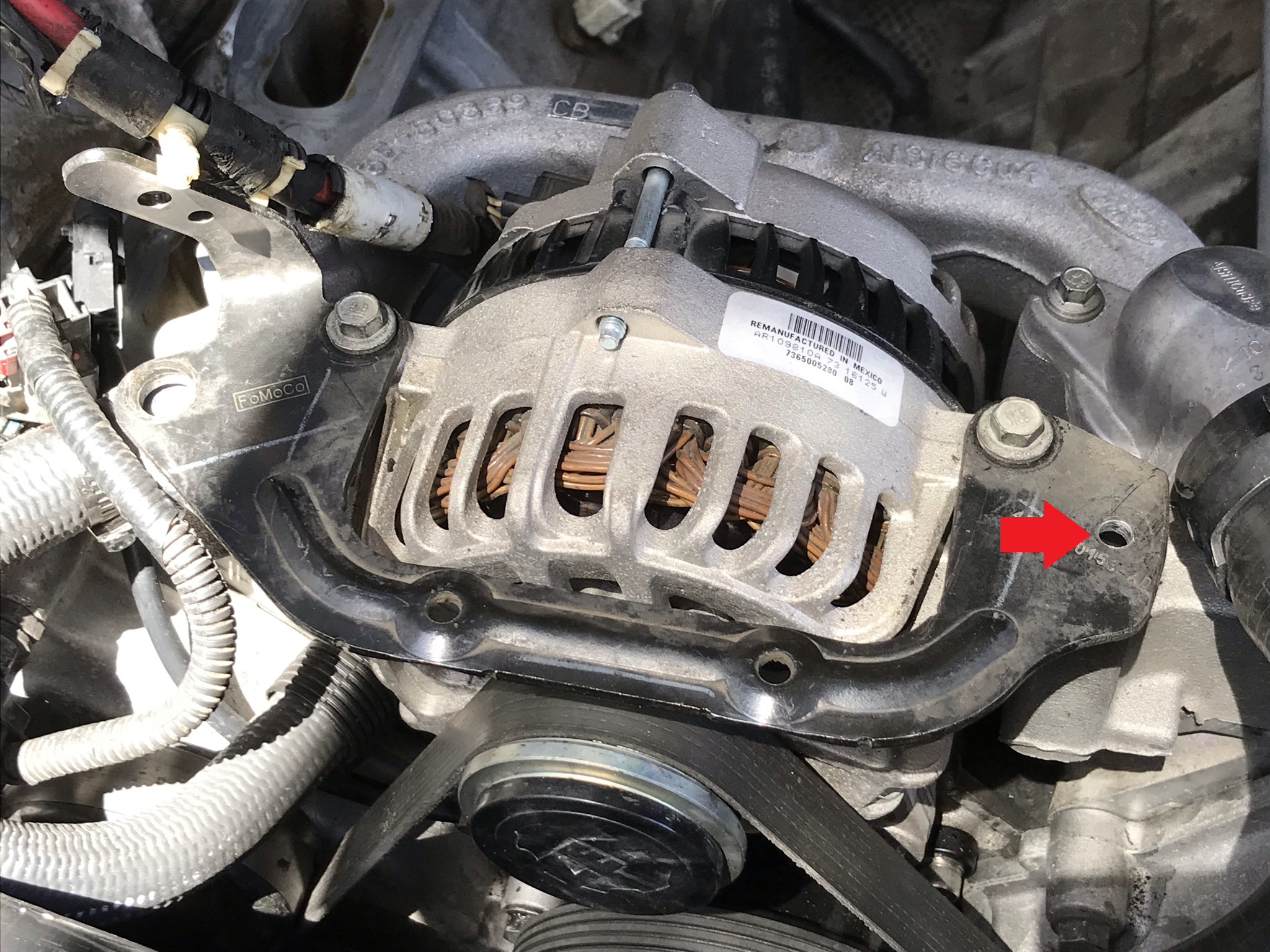
Besides the extra horsepower bonus, the Meziere pump doesn’t vary flow with engine rpm, which also means that it won’t cavitate at higher rpm or flow too little at lower rpm. Just a constant 55 GPM all the time. (Image/Christopher Campbell)Meziere’s pumps use 200 watt motors that, at full load at 12 volts, can run up to 16.6 amps. Meziere says the typical observed load is more in the range of nine amps for their standard pumps and 12 amps for the high-flowing versions. (Image/Christopher Campbell)There isn’t much disassembly necessary to start this project, but you will need to remove the air intake tube from the throttle body. Our project has a no-tune-required 50-State K&N FIPK cold air kit that makes the removal a little easier. (Image/Christopher Campbell)This is a quick install, so if you have a similar style cold air kit, you may find that all you really need to do is take the tube loose from the throttle body and then rotate it out of your way. This will provide fill access to the serpentine belt and water pump. (Image/Christopher Campbell)Before removing the serpentine belt, it’s a good idea to use the belt friction on the pulley to break the bolts loose. If you have an impact or cordless ratchet that is the quickest route. If not, two ratchets (or wrenches) opposing each other will work. (Image/Christopher Campbell)Once the water pump pulley bolts are loose, use a 1/2 inch drive ratchet or torque wrench inserted into the tensioner arm to rotate it to create enough slack in the serpentine belt to slide it off. (Image/Christopher Campbell)Believe it or not, we’re already to the step where need to prep the Meziere pump for installation! Modular Ford engines use an O-ring to seal to the block, so the only real preparation is to apply a bit of lube so that it slides into place without kinking. We used a very light smear of Super Lube synthetic grease. (Image/Christopher Campbell)Our current Edelbrock Victor water pump has never let us down, so we’ll be saving it in case we need to go back to a mechanical pump. There’s actually no real trick to the removal here. Once you remove the four bolts, grab the pump snout and wiggle it a few times to loosen the O-ring from the seated position. Have the Meziere pump sitting nearby for the quick swap and when you’re ready, just give the mechanical pump a quick yank, it should slide right out. (Image/Christopher Campbell)You’ll get an initial splash, plus a small amount of coolant flowing out while you squeeze in the electric pump, but all in you shouldn’t lose more than a couple of pints of coolant before the Meziere pump blocks the flow with its O-ring. Here was the amount of coolant spilled during our quick swap. We thought about making a video, but we figured five seconds of coolant spilling wasn’t that interesting. (Image/Christopher Campbell)With the Meziere pump in place, rotate the housing by hand if the bolt holes don’t line up. The pulley is not removable, so Allen head bolts are included in the kit. With a ball-tipped Allen wrench, it’s easy to drive them in despite the angle required. Well, three of them. That bottom bolt is probably the most annoying part of the install. Once it’s snug, you can slide the serpentine belt over the Meziere pump idler pulley. (Image/Christopher Campbell)The Meziere pump only requires two wires to function, but to safely integrate it into a stock electrical system we recommend their wiring kit that clips into the Meziere pump’s weather tight plug. (Image/Christopher Campbell)There are many acceptable ways to wire the Meziere pump, including on a manual switch. The easiest and more integrated way we’ve found is to use the factory fuse box, which is located conveniently close to the water pump. (Image/Christopher Campbell)Rather than tap into any wires, we’re going to use a Bussman “add-a-circuit” to get our 12 volt ignition trigger that will close the relay. This lets us tap into a switched 12 volt source without cutting a wire. (Image/Bussman)The two best options are circuits 40 and 42, which are coded as Engine 2 and Engine 3, respectively. Fuse 42 is live when the key is on, fuse 40 is live only when the engine is running. We went with 40, choose what you prefer. (Image/Christopher Campbell)Here’s the layout of the wiring you need. Battery power for the relay is tapped at the main power stud for the fuse box, and 12 volt switched comes from our add-a-circuit on fuse #42. The blue wire runs back to the Meziere pump, and the black is ground. We chose to mount our relay using a factory hole in the sheetmetal next to the fuse box. We’ll wrap these wires with braid to clean everything up. (Image/Christopher Campbell)The main ground source for the battery is just behind the fuse box on the passenger side strut tower. We added the relay ground and the ground from the Meziere pump to this location. (Image/Christopher Campbell)If you have a 2007-10 Mustang GT, clip in the 20 amp fuses because you’re done! If you have a 2005-06 GT like ours, this swap still works, but there is an additional recommendation for peak cooling: swap to the 2007-10 style coolant crossover and hoses. We’re going to do that with phase two of our project. (Image/Christopher Campbell)Here’s the odd mess that is the remote thermostat housing on 2005-06 Mustangs. It works fine for mild cars but can present problems for highly modified cars that build heat quickly. It’s also in the way of most forced induction systems. The 2007-10 version is greatly simplified and was standard on the FR500 factory race cars. (Image/Christopher Campbell)To swap to the later cooling system style, the intake manifold must come off. Luckily, 4.6 3V engines have a lightweight dry intake that pops off with only 10 bolts. (Image/Christopher Campbell)With the intake and the upper alternator bracket removed, you can get a clear look at the 2005-06 Mustang coolant crossover. This style has an outlet on the driver and passenger side. The passenger goes to the top of the radiator, the driver side goes to the remote thermostat housing. Also note the heater core hose in the valley. This connects to a port on the bottom of the coolant crossover in a Mustang. (Image/Christopher Campbell)This is the thermostat housing for 2007-10 4.6 3V engines. Well, it’s at least one of the options. The key thing to note here is there is only one radiator outlet on the driver side and the thermostat is housed on the crossover pipe itself. Sadly, these are long obsolete from Ford and are not reproduced anywhere. (Image/Christopher Campbell)Our coolant crossover is actually not for a Mustang; those can be expensive and fairly hard to find. Ours is likely from an F150 and is much cheaper and easier to find. We found ours online, the Ford part number is 7R3E-8C369. This version does not have the heater hose outlet in the engine valley, and instead exits toward the passenger side. If you can find the Mustang version for a good price, grab it, but we’ll show you how to make this version work. (Image/Christopher Campbell)Thanks to the fine folks at our local auto parts store for allowing us to stand in the back and test pre-molded heater hoses for 30 minutes, we found Gates part number 19203. We have no idea what the original application is, but it’ll work great for our swap. (Image/Christopher Campbell)We cut off the first 1.5 inch of the hose and voilà! It slides on the heater hose outlet then curves around and easily tucks through the gap between the head and alternator. We added a short piece of corrugated hose covering for abrasion protection. This hose will connect to the heater hose in the valley. (Image/Christopher Campbell)The second most challenging thing aboutremoving the original radiator hoses are these factory clips, assuming you don’t have the proper pliers. This would be a great time to upgrade them, but they will work just fine for the swap. The hose itself may be a little stuck on the radiator, but a firm twist should break it loose. (Image/Christopher Campbell)This is the most challenging, in our opinion, the lower radiator hose on the engine. It’s in a cramped spot and ours required cutting it off the outlet to removed thanks to thousands of heat cycles practically bonding the rubber to the metal. (Image/Christopher Campbell)This is the Mishimoto silicon hose kit for 2007-10 Mustangs that we’ll be using to update our coolant hose routing. Not only do these hoses have a nice, clean look to them, one of the best things about silicon is that it won’t stick to metal like the rubber hoses. (Image/Christopher Campbell)For better perspective of this swap, here’s the 2005-06 style Mustang hoses and remote thermostat housing next to the 2007-10 Mustang Mishimoto hose kit. The remote thermostat and the four hoses coming off it are replaced by the Mishimoto lower hose that feature one offshoot that goes up to the degas bottle. (Image/Christopher Campbell)Our thermostat of choice for our street legal track project is the Mishimoto 160 degree. Let’s clear up one common misconception right away; a lower temp thermostat will NOT help your car run cooler if you are reaching the thermal capacity of your cooling system. That is mostly governed by the water pump and the ability of the radiator and fan to transfer heat. However, if you are well below thermal capacity, it will allow the car the run cooler. Opening at a lower temperature will also get the water flowing quicker, which should result in more run time on track before any running into possible cooling issues. (Image/Christopher Campbell)To clear the thermostat housing, the 2005-06 style upper alternator mount requires the outer mounting hole on the driver side to be cut off and a new one drilled to match the new mounting location (red arrow). If you have a Mustang coolant crossover, that should be all that is required. If you have one like ours, you’ll also need to tap the blank boss on the passenger side. We’ll deal with it later. (Image/Christopher Campbell)This is how the completed swap looks with the 2007-10 Mustang Mishimoto hoses, our custom heater hose, and the trimmed upper alternator bracket. Notice how much more open room there is in front of the engine without the remote thermostat. (Image/Christopher Campbell)And here we are all buttoned back up! You’d have to be a real mod motor guru to notice our cooling upgrades aren’t original equipment. We haven’t had our project on track yet, but we can report that after refilling the radiator our coolant temps dropped by 20 degrees from 195 to 175 while testing around town with the A/C on. We’ll update this article when we have track day data. (Image/Christopher Campbell)
Christopher Campbell has been heavily involved in the automotive world since he began building his first car, a 1967 Ford Ranchero, with his dad at the age of 14. That started a lifelong passion with custom hot rods and muscle cars. After graduating from Cal State Long Beach, he went to work for HOT ROD magazine as Associate Editor. From there he became Technical Editor at Popular Hot Rodding magazine. Currently he creates freelance content for OnAllCylinders as well as many diverse enthusiast magazine titles such as HOT ROD, Muscle Mustangs and Fast Fords, Mopar Muscle, Super Chevy, Mustang Monthly, and 8-Lug.
Comments
3 responses to “Easy Power Plays for 4.6L 3V Mustangs (Part 1): A 20 Minute Meziere Electric Water Pump Upgrade & 2007-10 Cooling System Swap”
Hi, i am about to do this conversion (2007-2010 coolant crossover) I have two questions for you that will help me do the conversion without any problems. #1 what size drill bit/tap do i use to tap the blank boss on the passenger side, #2 how do you connect the gates 19203 hose to the OEM heater hose? I ask this two questions because they don’t show on the video. Thanking you in advance for any help you may give me to finish this project.
Hi George,
Sorry for the late reply, you happened to catch me out on vacation.
#1: I actually have not bothered to tap this yet, but it should be an M8-1.25 bolt. You can verify this by taking one of the factory bolts to your local hardware store.
#2: This depends on whether you have already patched the common fitting leak under the intake or not and how it was done. In my case, my factory hose was already cut to replace the fitting that connected to the original thermostat housing. I removed this fitting and used a hose splice to connect the factory hose to the Gates PN 19203. This has worked great for the track events the car has attended since the upgrade.
Looking for a 2007 to 2010 thermostat crossover need help please