
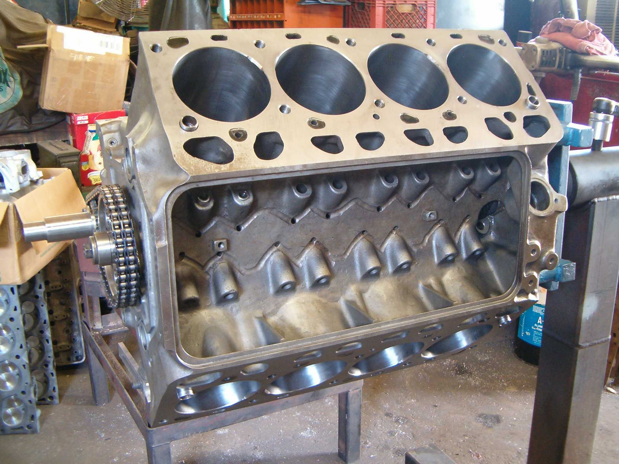
Ford’s first overhead valve V8, the Y-Block, remains the engine of choice for a lot of hotrodders. By modern standards, the Y-Block is dated with its stacked intake ports and solid tappets that must be installed first.
It is also—by far—the most handsome V-8 ever done. Introduced in 1954 to replace the time-proven flathead and displacing 239ci (Ford) and 256ci (Mercury), it was a bold first step by Ford to get away from the venerable flathead. It was long overdue.
In 1955, Ford pumped up the Y-Block’s displacement to 272ci and 292ci. In 1956, Ford grew the Y-Block to an optional 312ci as a bold displacement option in a competitive market. Ford had renewed respect from the competition and the close attention of car buyers because it finally had a powerful modern V8. In 1957, Ford offered two optional 312ci performance engines with either two four-barrel carburetion or a McCullough supercharger for those with additional cash on their hands during a bad economic recession. Having an “E” or “F” engine code Ford was real status in 1957.
When the Ford FE Series big block was introduced for 1958, the Y-Block took something of a back seat to these new mills, considering the larger FE engine’s displacement and power. There was also the Ford MEL Series fat block V8 for Mercury-Edsel-Lincoln luxury carlines, which was in a heavyweight class by itself. The Y-Block lived in production through 1964 and was a hard-working heavy hitter because it found purpose in so many applications. To this day, enthusiasts love the Y-block for its throaty sound and chatter of 16 traditional solid tappets. There’s just nothing else like it.
Two engine builders stand out more than any other when it comes to Ford’s Y-Block—Ted Eaton and John Mummert. There’s no one else in the world who knows more about the Ford Y-Block than these two gentlemen. Mummert calls San Diego, California home and is well known and respected for his Y-block efforts, including aluminum cylinder heads and induction systems for these legendary Ford V8s. Ted Eaton in Lorena, Texas knows the Y-block like few others. He builds a lot of them.
John Mummert of John Mummert Machine tells us block identification numbers are found on the side of block above the oil filter on Cleveland blocks (“CF” logo). Blocks cast at the Dearborn iron foundry (“DIF” logo) have block identification numbers near the distributor in back or above the generator. Most Dearborn foundry blocks were used in trucks, yet no Dearborn Y-blocks were produced after 1957, which adds to the confusion. Heavy-duty trucks were fitted with steel cranks and used C1AE or C2AE blocks, which were produced for both car and truck lines.
Nearly all Dearborn blocks cast after 1954 were 272s. Most 292 and 312 blocks were cast at Cleveland. John tells us it is generally believed no 312 blocks were ever cast at Dearborn. He also confirms 312 block casting numbers as ECZ-6015A, ECZ-6015B, ECZ-6015C, EDB-6015E, B9AE-6015F. Of these the ECZ-6015A and ECZ-6015C are the most common.
John also tells us some 312 service replacement blocks are numbered C2AE-6015C. What’s more, he adds 312 main caps are always marked “ECZ” while all other Y-block main caps are marked “EBU.” He stresses this is the only positive way to correctly identify a 312 block.
Although the 312 remains the most popular Y-block, you can get by with a 272 or 292 block with great success. John says nearly any 272, 292, or 312 block can be used for performance applications if massaged correctly. The 272 block can be bored to 292ci without consequence. Since all other internal components are the same across the board, you can cross pollenate. He adds that 292 pistons are easier to find, cheaper, and have a better ring selection.
John goes on to tell us the 292 blocks from 1955 to 1964 are easier to find. In fact, improvements were made to 292 and 312 blocks in 1959 with deeper drilled main cap threads for added strength. The 1961 to 1964 C1AE and C2AE blocks have additional material in the main webs for added strength. These blocks typically don’t sonic check as thick as earlier blocks according to John. Therefore, he adds, if a good early block is found, drill and tap the main bearing cap threads deeper and use the early block.
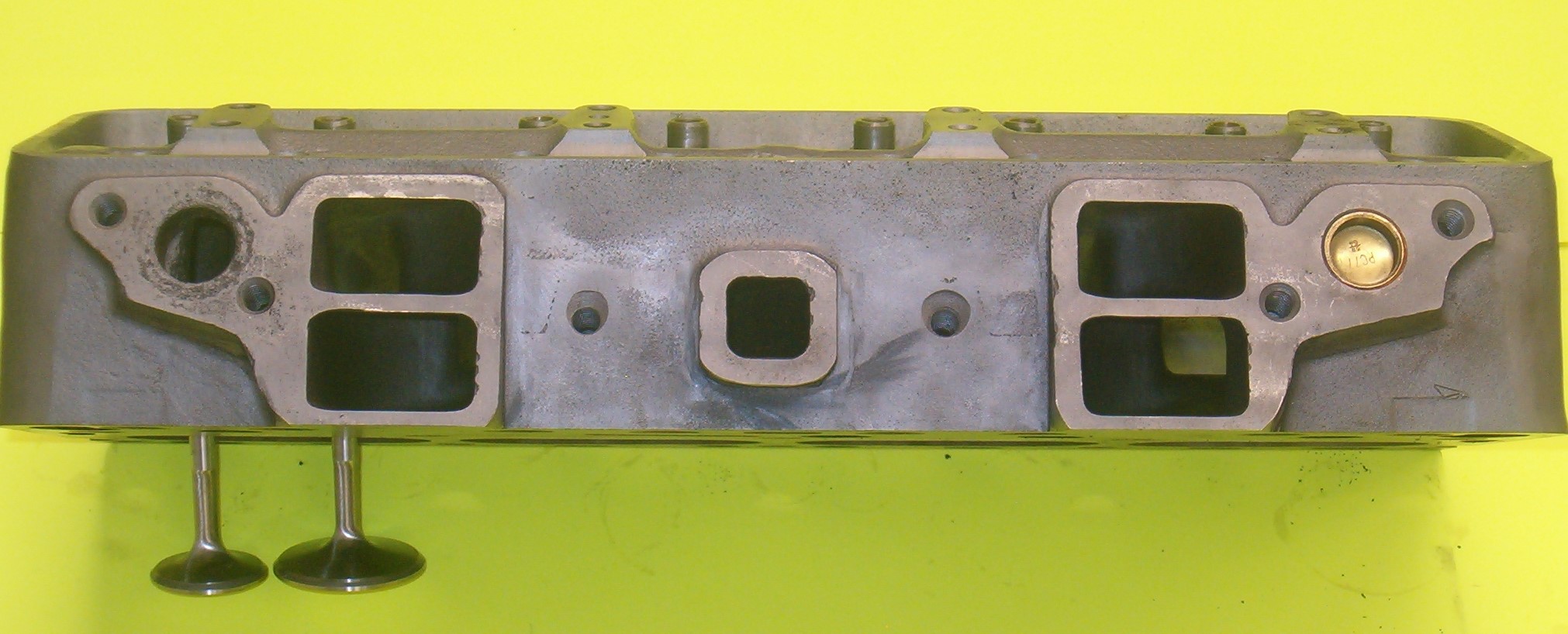
Cylinder Heads
The ECZ-C cylinder heads were used across the board on the 272, 292, and 312 engines. It is good to opt for stainless steel valves and hardened exhaust valve seats for use with unleaded fuels. The most desirable Y-block heads for increased compression are the 1957 through early 1958 ECZ-G castings with intake valves sized at 1.927 inches, according to Mummert. Combustion chamber size is approximately 69cc.
For slightly lower compression for today’s pump gas is the 1958 to 1959 “5752-113” casting. These heads have the same 1.927 inch intake valves and a slightly larger chamber, which lowers compression. For low-compression engines the 1959 “5750-471” truck head is also a good choice, Mummert adds, with a 1.927 inch intake valve and 80cc chamber. It is the same head casting as the “EDB” supercharger head, yet with a different casting number.
Mummert stresses some very important points you need to pay attention to. Never throw away your old Y-Block camshaft until you’ve captured the thrust spacer. The new aftermarket cam will not come with one. If you’ve already thrown it away, check with John—he may have one.
John explains there appears to be two different length head bolts for the Y-block—five short bolts near the spark plugs and five longer bolts under the rocker arm assemblies. The five short bolts near the spark plugs are identical but the five under the rocker arms are not the same. Two of these cylinder head bolts are slightly longer and installed at the outer ends of the cylinder head where alignment dowels are located.
It is good advice to lay all 10 long bolts next to each other on the bench and you will find four longer and six that are about 1/4 inch shorter. Installing the longer bolts in the center three holes can cause them to bottom in the block, which can be disaster. Late production Y-block engines have only long and short bolts.
John adds both Y-Block cylinder head gaskets are identical. It might seem that the same face of the gasket would go against the block and the opposite face would go against the head on each side. Mummert stresses this is not true. What is critical is that the open coolant holes are located at the back of the head and the blocked portion of the gasket is at the front. Otherwise you will experience overheat due to no circulation. Look for the word “FRONT” on the head gasket and place it at the front, even if it looks upside down. This places one of the gaskets face up and one face down.
Note there is a square corner at one end of each gasket. The square corner must be at the front of the engine. This can be checked without removing the heads. If you are having overheating problems, check for these square corners at the top front corner of the head near the intake gasket to confirm installation.
John stresses if you’re using a camshaft with a cross-drilled center journal you must use 1955 through early 1956 cam bearings designed for cross-drilled camshafts. If you’re installing a cam with a grooved center journal you must use the late 1956 to 1964 cam bearings. If your cam will not fit in the block check it for trueness. John has seen some cams with up to 0.010 inch runout, which should not be used. Another issue seen is the front cam bearing cocked in the bore. Install the front cam bearing from the rear to ensure proper installation.
Never throw away your old Y-Block camshaft until you’ve captured the thrust spacer.
Mummert repeatedly stresses installing rocker arm shafts right side up for lubrication purposes. He adds rocker shaft stands are identical and will bolt down either way. However, the oil hole in the shaft must be aligned with the hole in the shaft stand and is at the bottom when the stands are bolted down. Get this wrong and you will starve the rocker arms of oil and wind up with valvetrain failure and engine damage.
The 312’s main caps are taller than the 292’s main caps. However, the 312’s #5 main cap is at the 292’s height to clear the rear main seal holder and the oil pan rail. This makes it possible to install any of the 312’s longer main cap bolts in error from the first four main caps in the #5 cap. They will bottom out. Some blocks are drilled deep enough to accept the longer bolts in the rear cap. Do not do this. There have been a few instances where the rear main saddle of a 312 cracked during assembly because the longer bolt was used and bottomed out.
Another issue has long been the incorrect torque specification of 120 ft.-lb. main cap bolt torque according to John, which was printed in all 1956 Ford Shop Manuals. This figure is excessive and has undoubtedly cracked main webs in 312 blocks. Torque main cap bolts to 95 ft.-lbs. It is also critical to check the amount of thread that will be engaged in the block before torquing.
Do not use main cap bolts in any Y-block that don’t reveal at least 7/8 inch of bolt thread when placed in the main cap. This may require running a bottoming tap into the main bolt holes. Later 292 engines have significantly longer main cap bolts, an indication that Ford engineers realized this need. Do not use bolts or studs that engage more than 1-1/8 inches of thread because the oil passages to the main bearings will be blocked.
Mummert also tells us not to use excessive-length bolts for the intake manifold. The intake manifold bolt holes in the cylinder head intersect push rod passages and too long a bolt can interfere with the push rods. Also be certain that the bolt holes in the heads at the rear of the manifold are plugged. These are the threaded holes that are unused but are drilled through into the push rod passage. Use short bolts for this application, with a 1/2 inch of thread to avoid the push rods.
Timing cover bolt length is yet another issue. If these 5/16 inch bolts are too long they will contact the front two cylinders and do severe damage. Apply sealer to bolts that enter the water jackets or you will have leakage. They are the two bolts above and below the water passages.
Although Y-block cylinder heads can be interchanged to either side of the block, don’t do this. Years of exposure to coolant and the resulting corrosion, the 0.906 inch holes at the front of the intake surface will not accept a freeze plug. When you’re installing cylinder heads, make sure the corroded 0.906 inch hole is located toward the front of the engine. The corroded hole can be reamed to a larger size and an oversize freeze plug installed. Remove all oil galley plugs and the oil filter adapter before having your block cleaned. Always have the block decks surfaced, main bearing bores align honed, and head decks surfaced. These castings distort after years of operation and heat-cycling.
John tells us Ford used two different thrust washer thicknesses and cam plates, which calls for your close attention. If you use the wrong combination of thrust washer and cam plate, there will be zero camshaft endplay and failure is certain as the engine heats up. Ensure you have at least 0.004 inch camshaft endplay.
And finally, some replacement camshaft cores typically have a glob of metal between the last lobe and the distributor gear. On high lift cams, this glob can be higher than the base circle of the lobe, which can do incredible damage. Place a lifter on the last lobe base circle and be sure the lifter clears this glob.
Engine Masters Challenge
Ted Eaton of Eaton Balancing entered Ford’s Y-block in the Engine Masters Challenge at the University of Northwestern Ohio many years ago to see what could be done with the Y-Block in brute competition. For the 2007-08 Engine Masters competitions years back, he built a 312ci Y-Block with .022 inch overbore and a stock stroke to get 316ci. The following year, there were major rule changes that affected his agenda. One rule change was increasing the rpm range in these Engine Masters dyno pulls with compression as high as 11.5:1.
He told us although the 316 looked good in the 2,500 to 6,500 rpm range, the rules placed his Y-block much lower in the field due to the allowance of roller camshafts and increasing rpm to 3,000 to 7,000 rpm. Ted added that he was already at a disadvantage by having to use stock iron heads given these revised guidelines. He just wasn’t going to do it.
Ted’s plan for this engine was a “square” 4.000 inch bore and stroke to get 403ci. He told us this combination probably would not have given the best results but would have given him impressive peak power numbers. Ted commented the 4.000 x 4.000 inch bore and stroke combination created water problems when he went wide open throttle at low rpm under load on the dyno. He opted for a smaller 3.859 inch bore coupled with a 4.000 inch stroke to get 375ci along with additional cylinder wall thickness from a “B9AE-F” 292 non-steam hole block. Ted told us though 3.700 and 3.800 inch strokes had been tried successfully with Y-blocks, he wanted to know how 4.000 inches of stroke would work with a 292 block. It was a risky proposition.
Ted went with a 292 crankshaft offset ground for mock-up purposes to get the 4.000 inch stroke coupled with a 1.889 inch Honda connecting rod journal with 3/8 inch rod bolts. This sounds like monkey motion, but it worked well for Ted. He cut a single rod journal down to Honda size and went to work with the mock-up phase. His concern was getting 3/8 inch rod bolts to clear the camshaft while still getting the lift he needed.
Ted found a smaller base circle camshaft was not going to work because he was already planning a camshaft with 0.376 inch lobe lift to get the 0.600 inch plus lift valve lift he wanted. Anything smaller than 1.150 inch would result in the lifters falling out of their bores. He added the 1.150 inch base circle camshaft would clear rod bolts only if he opted for 0.337 inch maximum lift lobe.
When Ted did the mock-up and confirmed he could get a 4.000 inch stroke inside a 292 block, he ordered what he needed to build and flog this engine. He ordered a 4.000 inch stroke Moldex 4340 billet steel crank with 2.4980 to 2.4988 inch Y-Block main journals and 1.889 inch Honda sized rod journals—obviously a custom grind. Instead of a Y-block crank flange, he opted for a FE/385-series big block crank flange to make it easier to find an SFI approved steel PRW flywheel mandated for the Engine Masters Challenge.
Ted went with 6.750 inch long Oliver connecting rods with Honda sized journals to get a 1.68:1 rod ratio. His wanted to make this engine less vulnerable to detonation. To get the 375ci desired, he went with Diamond ceramic-coated pistons with special low-friction skirts for reduced friction. Compression height was 1.000 inch, which put the wrist pin into the ring lands. This meant he needed an oil ring support rail to prevent oil ring distortion. A 0.866 inch wrist pin and 9cc reverse dome got Ted the desired 10.1:1 compression ratio. Actual working compression was 8.0:1 with the cam advanced 1-1/2 degrees and valve lash at 0.025 inch hot. With the decided dated Ford iron heads, this was how Ted did it with 91 octane fuel. With aluminum heads, his 2009 Engine Masters entry could have enabled a higher compression ratio.
Ted tried seven different intake manifolds with a variety of carburetors and spacers. The final choice was the Mummert intake manifold and a Holley 950HP (834 cfm) and stepped headers (1.75 and 1.875 inch tubes feeding into modified 3-1/2 inch collectors and mufflers. Ted managed to get 462 to 464 horsepower and 446 to 449 lbs.-ft. of torque through the mufflers on the dyno, which was good considering 10.1:1 compression on pump gas. Ted tells us they tried a 1,050 cfm Holley Dominator and got tremendous torque from this combination.
At the 2009 Engine Masters Challenge, the engine fired nicely and ran smoothly at 900 rpm. He jetted the Holley carb at 77/89. It had been jetted at 75/87 in Texas. The jet change was a good decision with the Eaton engine making 433 horsepower and 416 lbs.-ft. of torque. A year later, Ted had the Mummert aluminum head advantage at the Engine Masters Challenge.
Ted felt it was time to bolt these Mummert heads, fully ported, onto his Y-Block test bed to see how these heads would do over fully ported iron castings at the 2010 Engine Masters. He gained another 72 horsepower over the ported iron stockers. He gave his 375 inch Y-Block seven quarts of fresh Valvoline 20w50 and put it back on the dyno for some road work. He managed 519 horsepower with the Mummert aluminum heads and induction package.
The Mummert heads were the only change. He then tweaked ignition timing to 32 degrees total to establish a baseline and without detonation. That said, he was able to push total timing to a whopping 38 degrees BTDC. He installed a modified and ported intake from Mummert with a carb spacer. The 375 suffered a minor loss in power at high rpm yet gained torque and average horsepower in at 2,500 to 6,500 rpm.
Ted took his 375 Y-Block to Ohio again for a series of floggings. With total timing at 38 degrees BTDC, Ted became concerned over potential detonation issues with such aggressive ignition timing. The decision was made to risk detonation and leave ignition timing where it was. Engine Masters rules in 2010 allowed for up to 11.5:1 compression. Static compression was 10.8:1. Ted opted for an Isky cam with 254 degrees intake duration, which figured in at 8.5:1 working compression.
Ted decided to let the oil get hotter in the sump while allowing fresh coolant into the engine at the same time. This netted Eaton 523, 521, and 524 horsepower for a total score of 2205.7 points—eye-opening performance from a vintage Ford Y-Block. The 375 came in 13th overall at the 2010 Engine Masters Challenge against a lot of tough competition (including Chrysler’s Hemi).
In the years since, Ted has returned to the Engine Masters Challenge with a succession of Y-Block entries—a 362-inch in 2015 with modified aluminum Mummert heads, a dual-plane manifold, and a Holley Dominator that came in third in a highly competitive field. Ted cammed these Y-Block entries for a street or drag racing, not necessarily dyno competition. In 2016, Ted returned with a 375ci Y-block conceived strictly for the Engine Masters Challenge. He came out on top with high honors.
In 2018, Ted returned to the Engine Masters again with a Y-Block engineered to turn in impressive numbers. He ordered up a Moldex 4.300 stroke crank. Custom made Jim Cunningham 6.500 inch connecting rods with a 45 degree rod cap were produced specifically to get the rod bolt to clear the camshaft. This enabled the tight confines of the block to handle a 4.500 inch stroke without rod bolts hitting the camshaft.
Ted kept the bore at 3.862 inches to achieve 403ci. Compression ratio was 13.0:1 with flat top pistons. Isky cam specifications were 0.629/0.639 inch valve lift with 256/260 degrees of duration at 0.050 on a 102 lobe centers. The real work was on top in the Mummert cylinder heads, which were ported along with a change in valve geometry to 16 degrees. Spark plugs were moved higher to near the roof of the chamber, permitted by the use of a smaller spark plug.
The Y-Block heads were originally designed with stacked intake runners to achieve equal-length runners. Where it got wild and crazy was custom work by Joe Craine to turn the Y-Block’s induction into a tunnel ram topped with Holley 660 cfm center-squirters. Where Ted got into trouble in 2018 was detonation issues on the dyno and the loss of the 403 engine. Still—he managed roughly 550 horsepower, which is remarkable for Ford’s venerable Y-Block.
Ted managed to take his Y-Block where no Y-Block had ever been before.


had a stock 312 in a 49 coupe, fun car.
wish i had niw
Have a few Y-Blocks Son has a 292 with super charger ,Impressive. several 56 fords ,All y-Blocks ,nice job keep up the good horse POWER
Ted Eaton built a 342 inch 292 for our 1955 T-Bird drag racer. John Mummert did the work on our iron heads. Made 510 HP @ 6900 on the dyno with approx 11:1 compression. Later we milled the heads 0.030” to raise the CR to around 11.75:1. Have not had it back on the dyno but 1/4 mile times improved by 0.15 seconds to a best so far of 11.11. Not bad for normally aspirated.
In my opinion, the Y-block Ford certainly was NOT the most handsome V8 EVER PRODUCED.
I can think of several that were better looking!
I happen to think the Buick Nailhead is more appealing, but I also really love the Chrysler Hemi, and consider the Chevy 348/409 the top of the line, when it comes to looks!
I guess you never saw a Ford 429 Boss, or a Ford SOHC 427!
I love the old y-block but a fe 427 built right will always be bad to the bone.
I own a 55 Town Sedan and think the y block is awesome! No plug wires laying on top the motor! Clean and simple! The three colors, red block, black valve covers and silver breather are true to the 50’s look! I am lucky because my vehicle came with the 182 special M Code engine. The sound out of the rear pipes is undeniable Ford Y block! I do not have people honking at me to hurry up and move from a light or on a hill!
That sounds nice. I am an old dog (77) but back in 64 I had a 54 Ford Mainline 2Dr Post. I was just out of HS worked for my dad in his Auto Repair anyway found a 312 from a wrecked 57. We Bored it .40 over, stuck a cam I got from Doug’s Racing Stables can’t remember the brand anymore but it was a thumper, headers and exhaust from Thunderbird Muffler shop topped off with Big Holly 4 barrel and 4:11 gears. I had so much fun with that car and in that day and age it held its own Paired up at the stoplight with all the Chevy boys in Tacoma city.
I am 83 and regarded as one of the few remaining in this locality that have messed much with the y block. 2.02 /160 small block Chevie+.300 or .200 stem length I forget which with the intake valve ground @a 30 rather than 45 degree angle and a 15 degree cut Bach toward the stem in the G series heads, seemed to benefit me more than any thing budget wise along with a recurved 57 or later distributor. I cut a grove in the block around the center cam bearing and install a .060 restriction in the base of the center rocker arm shafts for positive rocker arm oiling. Due to the valve lifters I’ll take a 302 /351 Windsor ant time. But what would a relic of antiquity know.
cam
I also am an old school prior Y-Block owner! I have always wondered what my mix-match replacement engine would profuse?
It was a 1955 Crown Victoria 2door hard top.
Started out as a 272ci 4 barrel automatic! My 17 yr heavy fool blew that
Wanted. 292, none were available! Went with 312ci .40 over bored short block. I kept the C heads. I blew the hell out of unsuspecting match ups. It would only run knock free on 100+ gas!
Top speed verified by MSHP Hwy 45 Scuba ,MS was 140+ MPH!
I have always wondered what the compression entail and output of this engine may hate been?
I have a 57 y block 292 with shaved 312 heads, crane hardware, stock bottom with isky cam defined as 1/4 race? Aluminum intake with 3 stromberg 97s headers and aluminum flywheel . Tricarbs are. Not the best choice especially with 3 on tree and 392 gears. But with the carbs dialed in right… this motor will take all the gas you give it and runs very strong! And the clakkety clack says to all lts got solid lifters . I’ve had it built this way 35 years ago and has never let me down and often I run it hard! It is one tuff motor! With this set up in a 53 F100 it will never be a dragster, But it sure would look good pulling one. Enjoy the ride …. the old fart,…. Cams and jammer club since 55 Thanks
Driving a57 rancho 292 was setting for 20 .years.runs great but over heating so got to work on that.
I have a 292/315 with a 60mm Turbocharged Y-Block that Ted Eaton did all the machine and balancing work. It makes 460 HP at the wheels of my ‘60 F100.. Fun to drive.. And when people ask
What the H… is a Y-Block
Where can I purchase a new Ford 312 complete engine?
i have a 272-312 ford ’57 t-bird engine. it has been dipped,cleaned and honed. i had the heads reworked with new parts. i have not assembled the engine as of yet, due my time limit. have every thing from fan to oil pan to dual intake to t- bird aluminum v-covers
i have a 272-312 ford ’57 t-bird engine. it has been dipped,cleaned and honed. i had the heads reworked with new parts. i have not assembled the engine as of yet, due my time limit. have every thing from fan to oil pan to dual intake to t- bird aluminum v-covers . can call at my c-phone,303-550-5823 or e-mail
Impressive, good work, I have this project of fitting a V8 Y-shaped bespoke engine into a Fiat 124 Abarth Stradale(1984) Hard Top but I am afraid that the engine bay is too small, or is it not?
Looking to replace the road tube with a PVC venting system. I have seen numerous alternatives. What is the best way to resolve the tube leak. 1962 292 Y
I need a gasket set for a B9AE 6015F…. Any ideas?
Dave 941 706 6898
Hey Dave, thanks for reading–didn’t mention what specific gaskets you needed, but Summit Racing carries plenty of gaskets for that motor, including full Y-Block gasket sets.
…
Click here to see the Ford Y-Block gaskets.
…
Hope this helps.
Hello to all I just found this on all cylinders site and after 3 hours of reading im hoping that anyone can help me?
I have a 56 f100 with a 272 with 3 on the tree and it’s time to rebuild everything so it can run down the road at 65/70 right now it runs tops 55 and that’s pushing it I’d like it to be able drive it on the highway I would love to see my wife driving it before I die.
I live in Prescott Michigan and don’t know anyone here that knows about the Y Blocks and the truck is original all numbers matching and would like to keep it original.
I’ll keep watching this site on all cylinders to see if someone responds and be able to make contact by phone or e-mail