You’ve got to hand it to Ford as a car company. It has history unequalled including four consecutive wins at Le Mans in the 1960s when it was all or nothing against Enzo Ferrari on the world’s stage. It was exclusively about ego and the age-old battle of winning at all costs. Henry Ford II wanted Ford to be a world class automaker with an impressive resume of global racing wins. To get there, he needed to acquire a European automaker with a reputation for winning. That automaker was Ferrari.
Ferrari, facing serious financial woes, was searching for a suitable buyer. Ford saw Ferrari as a means into the European market and worldwide racing success. Then, as now, what wins on Sunday sells on Monday. It could be nothing but good for Ford. Car buyers like hitching their wagons to successful car companies though this has never really made a difference in the end. You may win races, however, if you don’t offer the customer a great product and reliability, they will never return for that second purchase. Ford learned this one the hard way in lost sales in the 1970s from disappointing quality and poor customer service. It wasn’t until the 1980s that Ford began to recover and regain market share.
(Image/Jim Smart)
Ford and Ferrari had been in talks for months about a deal for Ford to acquire Ferrari. Ferrari faced tremendous regional pressure for selling out to an American automaker. When it came down to the wire, Ferrari backed out, which made Ford’s blue blood boil. Ford wanted complete control of Ferrari’s racing operations as part of the deal. That wasn’t going to happen at any price.
Mr. Ford decided to build one heck of a racing operation within the Ford Motor Company and beat Enzo Ferrari at his own game. The goal was to kick Ferrari’s butt at Le Mans. Getting there would be a monumental task. Ford’s great racing success began domestically at Daytona, Sebring, Road America, Watkins Glen and a host of other racing venues. These wins prepared Ford for the exhausting journey to Le Mans.
Winning Le Mans was never going to be easy for Ford. Defeats in 1964-65 turned up the heat at Ford. Mr. Ford’s words were simple and concise to Carroll Shelby and Ken Miles. Either win Le Mans or be fired. Of course, Ford was never going to find anyone as qualified as Miles and Shelby. It was a moot point because Mr. Ford had the best. Carroll Shelby, who was never short on words, explained to Ford what it was going to take to win. It was going to require more money and resources to win Le Mans. Shelby’s position was simple—either get on board or stay on the porch. It was risky business to tell Mr. Ford how the cow ate the cabbage. However, Shelby had Ford’s attention and support. Beat Ferrari at all costs.
At Le Mans in 1966, Shelby and Miles, and drivers Bruce McLaren and Chris Amon came in with Ford’s first Le Mans win. There would be more. That spectacle was followed by three consecutive Le Mans wins—Ford’s glory, and surely Ferrari’s public humiliation—spanked by an American supercar and a large V-8. This took great teamwork—world class drivers and the eye-opening Ford GT—to corral these wins. Ford was center stage using the phenomenal power of an American big-block V-8 and the experience of seasoned drivers who knew how to stay the course and win.
At the heart of these Le Mans wins was Ford’s 427ci “Side Oiler” FE Series big-block V8. The Side Oiler was the result of extensive research and development and having your keister handed to you repeatedly on the racetrack. Ford learned in educational baby steps how to make the 427 more durable. This quest began in 1962 with the 406 and a cross-bolted main cap block. Only very few 406 engines were cross bolted, swiftly replaced by the big-bore 427.
Cross-bolting the 427’s main caps and giving the block thicker main webs were valiant first steps. Still—racers continued to scatter 427s all over racetracks from coast to coast, especially in NASCAR competition. The remaining issue was lubrication. The FE’s oiling system fell short, with main bearings becoming oil starved at high rpm. Ford engineers had to develop a completely different “side oiling” system that ensured main bearings got adequate lubrication. The “Side Oiler” 427 was born.
Once Ford achieved solid durability in the 427, it went to work on the GT40 racecar chassis, which was a tremendous challenge. It took the extensive knowledge and experience of Miles and Shelby to make the GT40 not only an endurance race finisher—but also a winner against Ferrari. It was a picture-perfect finish with Ford leading the pack ahead of Ferrari. What’s more, Ford did it three more times before Mr. Ford concluded there was nothing left to prove. Ford got out of racing.
Carroll Shelby’s objective, aside from winning Le Mans, was also to design and build the world’s fastest production sports car — and he did in 1965. The 427 Cobra did 0-60 mph in 4.2 seconds, 0-100 mph in 10.2 seconds, and had a top speed of 160 mph. It tipped the scales at 2,350 pounds with more than 500 horsepower.
Shelby’s 427 Cobra held the crown of world’s fastest production car (0-100-0 mph in 13.2 seconds) for more than 30 years before Ferrari caught up and passed the Cobra in more recent times. In competition form, the Cobra was a Ferrari-spanking 580-horse powerhouse using real American V-8 power. In street form, the Cobra was closer to 500 horsepower. Cobra magic came of a sweet US/Britain alliance that has been solid for approaching 60 years.
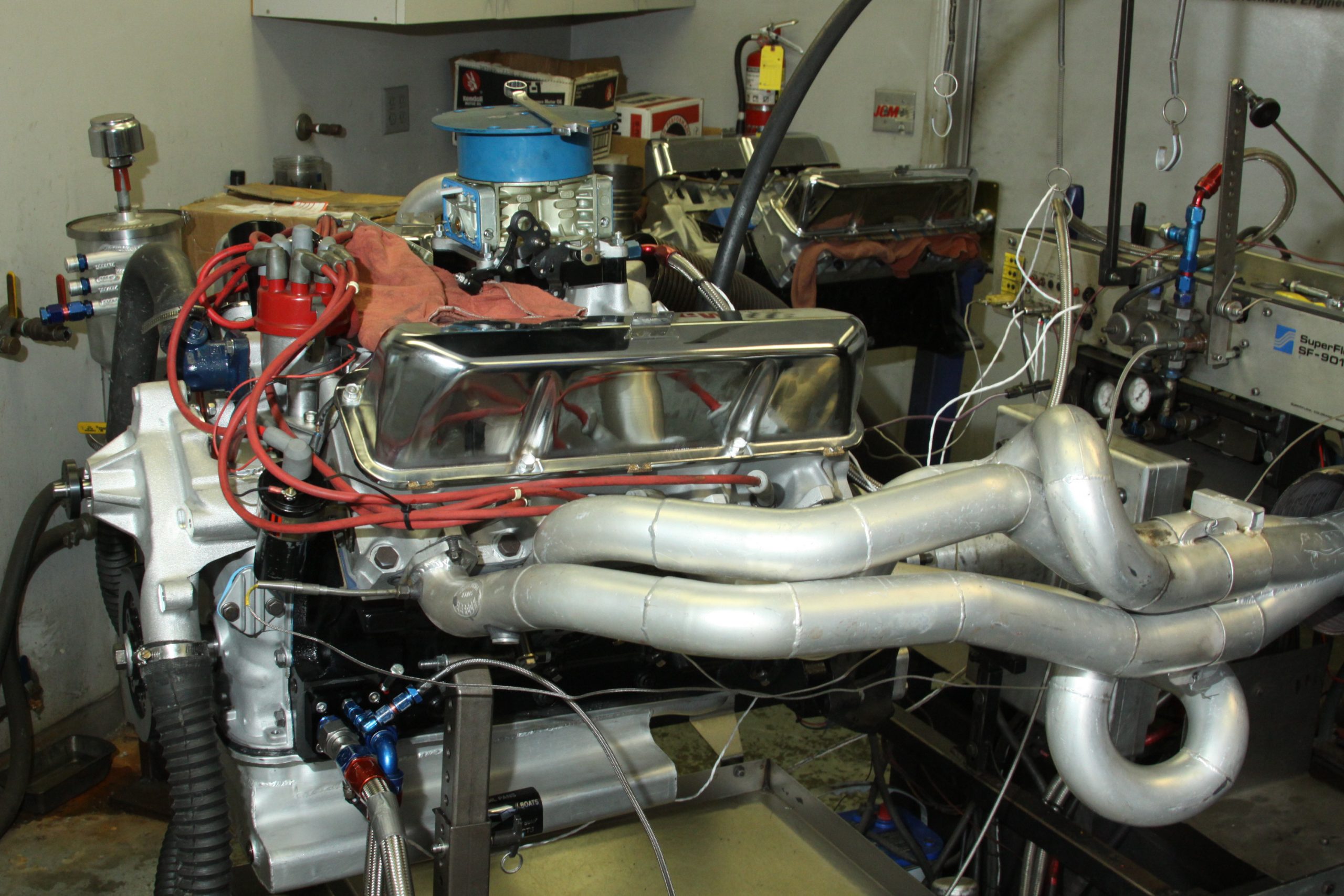
We’re at JGM Performance Engineering in Valencia, California covering a unique 427 Side Oiler from one of those historic 427 Shelby Cobras—the real thing (CSX 3147) from Shelby’s racing facilities in Southern California a lifetime ago. It is a rare privilege to be invited into the JGM shop to cover a build like this. What makes this 427 build unique aside from the obvious is its limited production “PROCESS FD” aluminum cylinder heads, which were produced in 1964-65 as a C5AE casting number and considered Medium Riser cylinder heads available over the Ford parts counter for a very limited time.
This 427 FE build gave us the opportunity to explore the Side Oiler block and get a closer look at the limited production PROCESS FD aluminum heads, which were a rarity at the time as Detroit became familiar with aluminum casting techniques. Before us was a genuine 427 Side Oiler that had lived in a production 427 Cobra since 1965. Seeing the “CSX 3147” hand stamped in the block casting gave us goosebumps. So did the “C5AE” casting numbers. This 427 had a front row seat for American automotive history in a sports car known to be the fastest production automobile in the world at the time. Not bad for raw American iron that also won Le Mans.
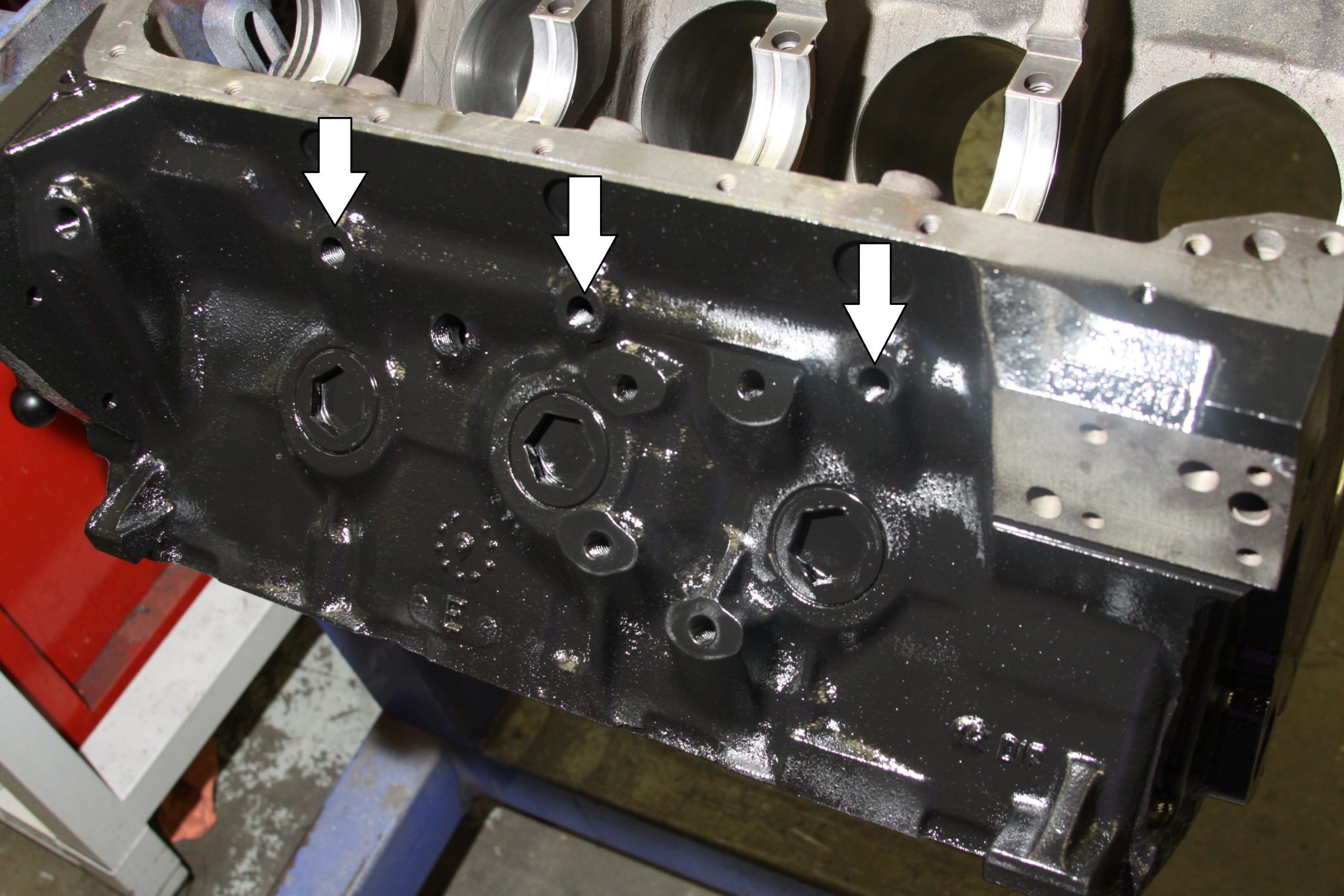
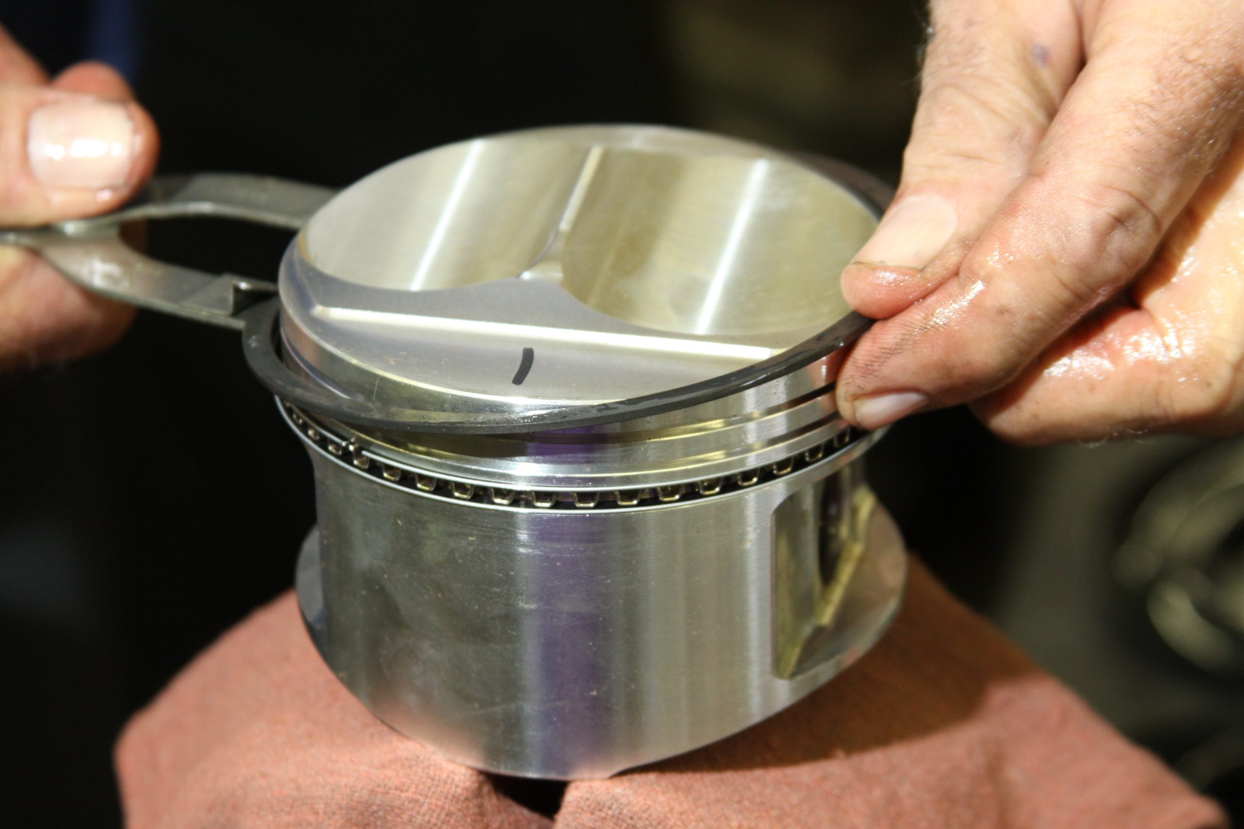
The bowels of a cross-bolted Ford 427 Side Oiler born for the legendary 427 Shelby Cobra. Three cross-bolted main caps coupled with a block-long duo of oil galleys to keep the bottom end lubed at 7,500 rpm. H-Series bearings will handle the demands of this guy on a racetrack. (Image/Jim Smart)The quickest way to identify the 427 Side Oiler block is the three oil galley plug passages on the left hand side of the block along the pan rail. (Image/Jim Smart)Because JGM is building an authentic period Cobra 427, everything needs to be circa 1965-66 including the flat tappet mechanical cam from COMP Cams (#33-000-5). Moly lube, Manley’s Moly Lube is applied to the lobes for proper break in and work hardening. COMP’s Engine Assembly Lube is applied to the journals. (Image/Jim Smart)Sealed Power main bearings are seated in the main saddles, taking care not to touch bearing surfaces. This is the thrust bearing in the #3 saddle. (Image/Jim Smart)JGM understands there are a couple of approaches to rear main seal end gaps. One approach is to position the end gaps away from the main cap parting surfaces with Permatex’s The Right Stuff at the seal tips and between the seal and main journals. Another is to keep the end gaps at the parting surfaces and use The Right Stuff at the seal tips. Check the seal grooves for irregularities and debris, which can cause leaks. (Image/Jim Smart)Main bearings and rear main seal are lubed with assembly lube. The seal must be fully seated in the groove with the lip turned toward the front of the block. If you install the seal with the lip pointed away from the block, you will have leakage. (Image/Jim Smart)This is an “XE” factory experimental steel crank with C-clips and oil galley plugs. Later on in production, 427 steel cranks had screw-in oil galley plugs for added security. (Image/Jim Smart)Main journals have been slotted from the oil galleys for improved oil flow. (Image/Jim Smart)Crankshaft endplay is checked and should be 0.004 to 0.008-inch. You don’t want anything beyond 0.010-inch. (Image/Jim Smart)With the main caps secured and torqued, side bolts are tightened next with 40 ft.-lbs. of torque in one-third values. Main caps have been torqued to 95 to 105 ft.-lbs. Side bolts get treated to The Right Stuff to prevent oil leakage. (Image/Jim Smart)FE Series engines have problematic rear main seals because there are so many ways for them to leak. Rear main caps side seals require close attention. Side grooves get The Right Stuff prior to seal installation. Don’t overdo it. (Image/Jim Smart)The seal is installed first with the main cap, then, this reinforcement pin is carefully driven in next. Be careful not to distort the seal. (Image/Jim Smart)This is the earliest Ford casting number you can expect to see on a Side Oiler—C5AE-H. (Image/Jim Smart)Shelby American stamped this block with the Cobra’s vehicle identification number—CSX-3147. The other characters are Ford inspector’s marks. (Image/Jim Smart)“DIF” indicates Dearborn Iron Foundry, Cavity Number 12. This engine would have been assembled at the Dearborn Engine Plant on the FE line. Look for an alphanumeric casting date code as well to confirm when the block was cast. (Image/Jim Smart)Before you can degree the cam, you must confirm true top-dead-center or nothing else will be right. Get #1 piston to top dead center using the degree wheel and dial indicator. Then, slowly turn the crank slowly each way until there’s piston movement, then, find dead center between the two points of piston movement. This is true top-dead-center. (Image/Jim Smart)Degreeing the cam is an effort to confirm actual cam specifications compared to the cam card. You may have to advance or retard valve timing depending upon your performance goals and any differences between the cam card and your findings. Based on JGM’s findings, it has chosen to retard the cam two degrees to improve high rpm horsepower numbers. This means giving up low-end torque. What we want most from the 427 is horsepower and a broader torque curve. (Image/Jim Smart)The C6AE-E Le Mans rod is exactly what the doctor ordered for the 427 in 1965-66. This brute rod was common in later 427s, then, there was a bolt change to make it compatible with the Super Cobra Jet rod. These rods have been shotpeened for strength and fitted with ARP bolts. (Image/Jim Smart)Engine builders all have their own approaches to piston ring installation. The objective is not to distort the ring whether you use a ring expander or choose to roll the ring on. These are JE custom forged pistons for this particular application. (Image/Jim Smart)Pistons should be thoroughly lubricated with SAE 30 weight engine oil or cylinder wall specific assembly lube, which is lighter than assembly lube. Smother the piston in lubrication to ensure a wet start up. (Image/Jim Smart)This is the 427 Side Oiler’s pressure relief valve as it is properly installed in the block. Spring first, then, valve piston with this pin pointed toward the screw-in galley plug. (Image/Jim Smart)If you have excessive pressure beyond 100 psi, oil is relieved to the pan. (Image/Jim Smart)Because we’re running a flat tappet Comp Cams camshaft, these lifters need moly lube on their bases for work hardening during break-in, and engine assembly lube around their circumference. Lifter bores have been honed for oil control. (Image/Jim Smart)Cylinder head to block sealing can be tricky with iron heads let alone aluminum. JGM Performance Engineering uses Permatex’s The Right Stuff in all of the FE’s leak spots. FE blocks, heads, and induction tend to weep oil here. Cylinder head torque is 110 ft/lbs for top bolts and 100 ft/lbs for bottom performed in one-third values. Although Fel-Pro says you don’t have to retorque the head, retorque the heads after a good break-in. (Image/Jim Smart)We like these limited production C5AE-6090-H PROCESS FD Ford aluminum Medium Riser heads for their rarity. Aside from good heat transfer, which enables you to run more compression, these heads offer little more in terms of performance—and they make great conversation pieces. Although these have been identified as experimental heads by the media, they’re little more than production Medium Risers with 2.180/1.720-inch intake/exhaust valves. They’re short on quench value. (Image/Jim Smart)Although these PROCESS FB castings have been identified as experimental heads, they’re little more than production “Medium Riser” castings with 2.180/1.720-inch intake/exhaust valves. They’re short on quench value. (Image/Jim Smart)Heads are installed and torqued to Ford specifications. Once this engine has been good and hot on the dyno, they should be retorqued to ensure sealing. JGM has opted for the old valve springs for break-in. These springs offer less seat pressure, which is optimum for break-in. They won’t wipe the cam lobes. (Image/Jim Smart)The Right Stuff is applied sparingly around the cooling passages and along the bottom of each intake port to prevent leakage. Any irregularities along the bottoms of each port can cause oil to be drawn into the intake ports. Use sealer sparingly—super thin—to avoid any excess winding up where it shouldn’t be. (Image/Jim Smart)Fel-Pro’s Print-O-Seal gaskets do an excellent job of sealing though The Right Stuff is crucial around cooling passages to compensate for irregularities in the castings and block deck angle. Another suggestion is to port match the heads and intake where possible. This is something you can do yourself with a die grinder or have your machine shop do a quick port match. (Image/Jim Smart)Before you is a unique period dual-plane magnesium manifold for the FE big-block, which was produced for a limited time in 1966-67 for the Medium Riser head. Although this manifold is a unique conversation piece, it makes virtually no sense for your FE project. It must be carefully torqued. (Image/Jim Smart)The FE’s fully adjustable rocker arm assembly is pre-lubed with assembly lube and readied for installation. (Image/Jim Smart)The 427’s valve lash is normally 0.025-inch cold and 0.022-inch hot (30 minutes idle time, no load). (Image/Jim Smart)We like the period Le Mans bowl Holley 4150 perched atop the magnesium intake, which aids authenticity. It is being dyno tuned by JGM along with ignition timing adjustments to see how much power can be achieved. (Image/Jim Smart)Here’s a closer look at the PROCESS FD heads. Although unique for the time they were produced, the aftermarket offers better choices today. (Image/Jim Smart)Total ignition timing during our dyno tune was 34-36 degrees BTDC. JGM managed to achieve 510 horsepower at 6,200 rpm along with 503 lbs.-ft. of torque at 4,200 rpm. This was about as expected from the combination of parts JGM used with this period 427. Fit this 427 with a nice aggressive roller cam, aftermarket Trick Flow heads and intake and you can expect 600+ horsepower along with comparable torque. (Image/Jim Smart)
Jim Smart is a veteran automotive journalist, technical editor, and historian with hundreds of how-to and feature articles to his credit. Jim's also an enthusiast, and has owned and restored many classic vehicles, including an impressive mix of vintage Ford Mustangs.
Comments
8 responses to “Rebuilding a REAL Ford 427 Side Oiler Cobra Engine: A Rarified Experience”
The story about Henry 11 being mad a enzo is true to a point but not correct.
According to Mrs Ford she was at dinner with Henry 11 and he was telling her he peoduced the finest racing engines in the world.
She replied that he didn’t and he asked her why not.
She then said that he hadn’t beaten Ferrari yet.
That is the real story of why Ford went after Ferrari.
i am in the process of rebuilding a 1966 427 side oiler and truly appreciate this write up and pictures as well as there is not alot of factual info on these somewhat rare engines.
I am Al at Heartbreaker Race Engines Chicago, I am in the process of building another 427 this time it is a brand new side oiler block I’ve been saving for many years now. I got it out the back door of a Ford dealer where my cousin worked 50 years ago. I like this ad and it’s info which is quite accurate and informative. The authors research and the photos are great. I commend the writer and this publisher. By the way: My side oiler is going into a 427 Cobra Coupe re-pop. Keep up the good work guys!
Jim — Thanks for the memories! While I never got into the nuts and bolts, I did tune, service and redline this engine back in 1968 when it had 8V and powered Shelby’s “Sports Car” street Cobra CSX 3147. I bought this “narrow hip” roadster on 2Jan68 from Larsen Ford in White Plains, NY. If the CSX 3147 chassis still runs and someone can get me in touch with the current owner, I have some interesting early history on this REAL 1966 427 Cobra.


The story about Henry 11 being mad a enzo is true to a point but not correct.
According to Mrs Ford she was at dinner with Henry 11 and he was telling her he peoduced the finest racing engines in the world.
She replied that he didn’t and he asked her why not.
She then said that he hadn’t beaten Ferrari yet.
That is the real story of why Ford went after Ferrari.
I love it… Great story…
i am in the process of rebuilding a 1966 427 side oiler and truly appreciate this write up and pictures as well as there is not alot of factual info on these somewhat rare engines.
I agree – as much as we want to include a lot of details – there is always information overlooked and forgotten.
I am Al at Heartbreaker Race Engines Chicago, I am in the process of building another 427 this time it is a brand new side oiler block I’ve been saving for many years now. I got it out the back door of a Ford dealer where my cousin worked 50 years ago. I like this ad and it’s info which is quite accurate and informative. The authors research and the photos are great. I commend the writer and this publisher. By the way: My side oiler is going into a 427 Cobra Coupe re-pop. Keep up the good work guys!
Tremendo trabajo tremendo profesional
Mencanto ese trabajo que iso
Mencantan esos motores
Tenia uno de esos
great information and photos.. the explanation of every step will help me proceed with my build .
Jim — Thanks for the memories! While I never got into the nuts and bolts, I did tune, service and redline this engine back in 1968 when it had 8V and powered Shelby’s “Sports Car” street Cobra CSX 3147. I bought this “narrow hip” roadster on 2Jan68 from Larsen Ford in White Plains, NY. If the CSX 3147 chassis still runs and someone can get me in touch with the current owner, I have some interesting early history on this REAL 1966 427 Cobra.
Cordially,
S. “CS” C.