Ford’s 289 High Performance V8, introduced in the 1963 Fairlane, is something of folklore and legend. It was factory rated at 271 horsepower at 6,000 rpm with mechanical flat tappets and was a delightful mill right off the assembly line.
Yet, much has been made of “rare” 289 Hi-Po parts, with enthusiasts paying outrageous sums of money for these components. However, you don’t have to buy Hi-Po parts to get high-performance. Everything you need to build a high-performance Ford small-block can be easily found from your favorite speed shop.
The only thing “high-performance” about the 289 High Performance V8 was a hot mechanical flat tappet cam, cast iron exhaust headers, larger 3/8-inch connecting rod bolts, a slide-on counterweight, wider harmonic damper, hand-picked Brinell-tested “1M” crank, stiffer valve springs, and unique cylinder head castings designed for high-rpm operation.
The 289 High Performance cylinder heads have exactly the same valve and port sizing as your mother’s grocery getter 289 2V or 4V engine. The rest are hand-picked and prepared parts you can assemble yourself.
Starting the Performance 289/302 Build
We’re going to show you how to build an affordable 289 High Performance engine without the expense of those rare Ford Hi-Po parts.
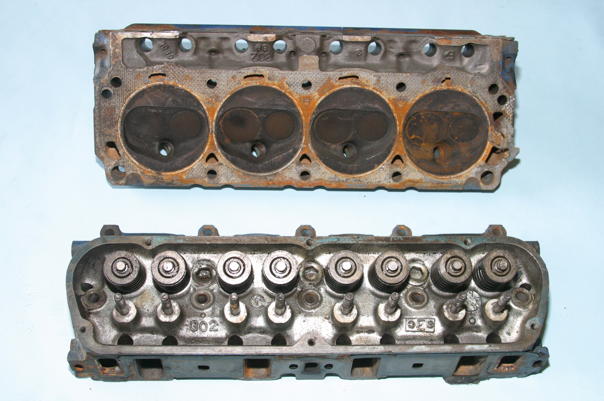
The best cylinder head to use is the 1960s 289 head casting with 53cc or 57cc chambers for the best quench and compression. Our subject engine is a 1967 289 with ’69 302 truck heads, which have larger 64cc chambers. These heads have been milled 0.010-inch, which will put us around 10.0:1 compression. With earlier 53cc/57cc chambers you’ll be at 10.5:1. They have also been CNC-ported and fitted with larger 1.940/1.600-inch Chevrolet valves for improved flow. These heads have been machined and fitted with screw-in rocker studs with guide plates.
We’re working with a 289 with some fundamental issues stemming from a previous rebuild. (The builder was decidedly sloppy.)
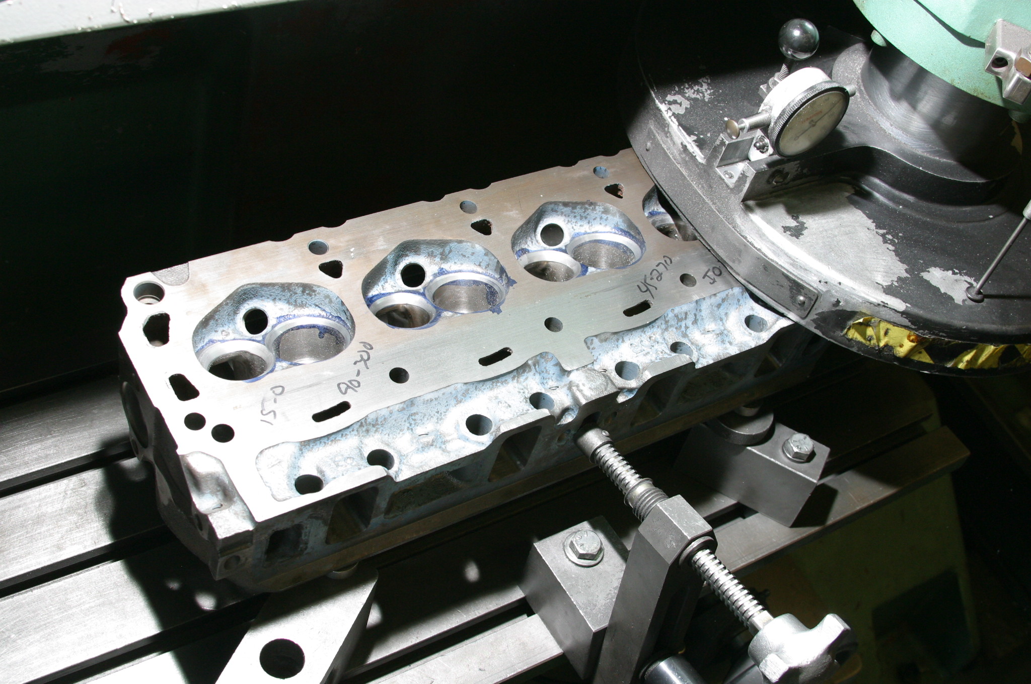
Because the cylinders were over bored, with excessive piston-to-cylinder clearances, we’re going to have to take these bores to 4.040 inches, which is as large as you want to go with a small block Ford. The line bore had to align-honed again to get it square. The decks were milled, but at an improper angle rendering the block almost useless. That causes intake manifold-to-cylinder head mating issues to where coolant and vacuum leaks have been a problem. This calls for tricky machine work on the heads and intake manifold to get things plum. At best, it is a dicey process.
JGM was able to get the decks true.
Although the factory 289 High Performance engine was fitted with a flat tappet mechanical camshaft, you have the option of an aggressive Comp Cams hydraulic roller that will give you a choppy idle and come on strong with rpm. The period-correct Comp Pro Magnum 1.6:1 rocker arms deliver low friction performance and the same exciting chatter you get with a mechanical cam, which will make your 289/302 sound like a 289 High Performance V8.
Finishing Up & Dyno Testing
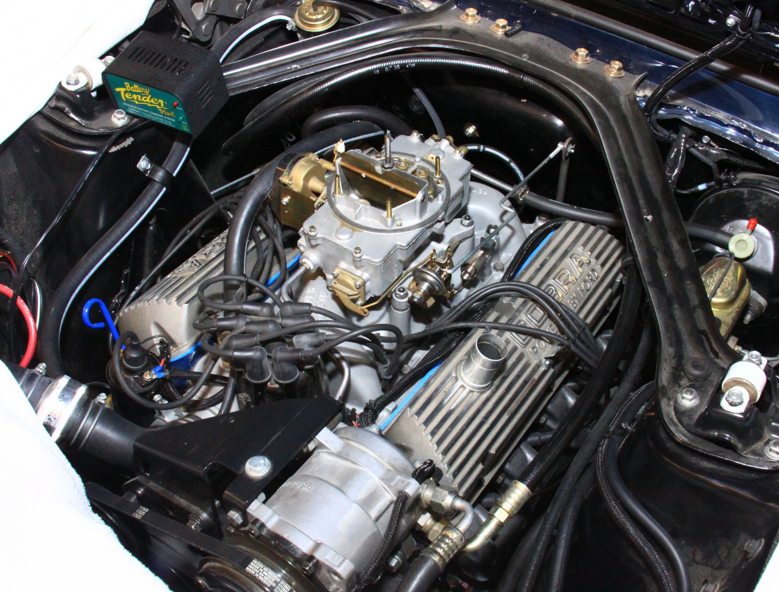
During final assembly, this hydraulic roller 289 was fitted with a Tony D. Branda reproduction Cobra high-rise dual-plane manifold and valve covers, and was fitted with an Autolite 4100 much as the ’66 Shelby GT350s were with automatic transmission.
On the dyno, this engine made 320 horsepower and comparable torque with a Holley 650cfm with vacuum secondaries and a stock Autolite distributor with a Pertronix retrofit and long tube headers. Not bad for what is basically a stock 289.
Check out the huge image gallery below for a visual walkthrough of the job.
***
Engine Bottom End & Rotating Assembly
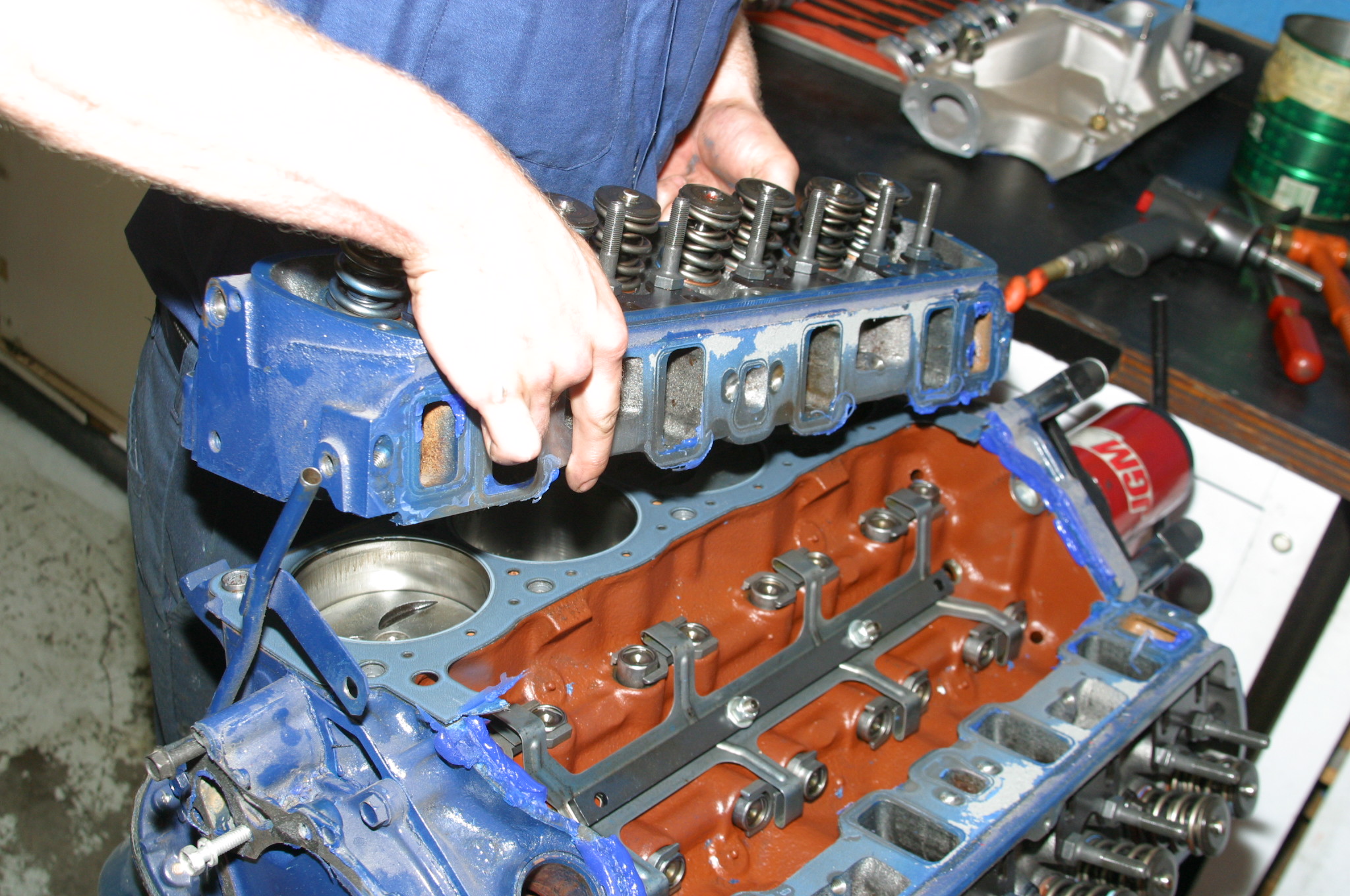
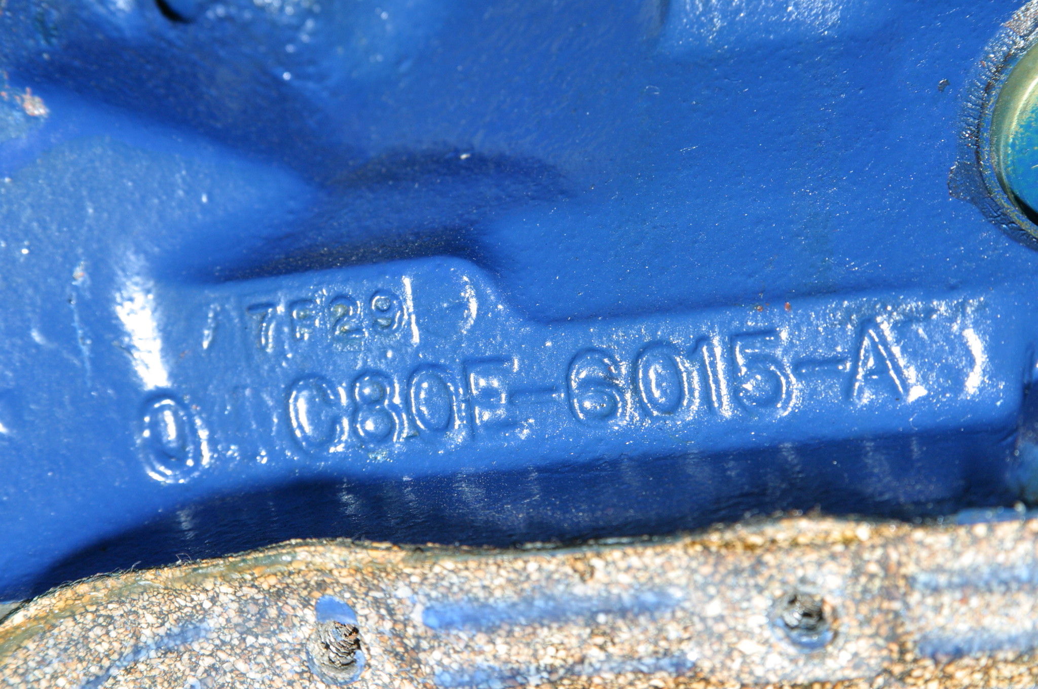
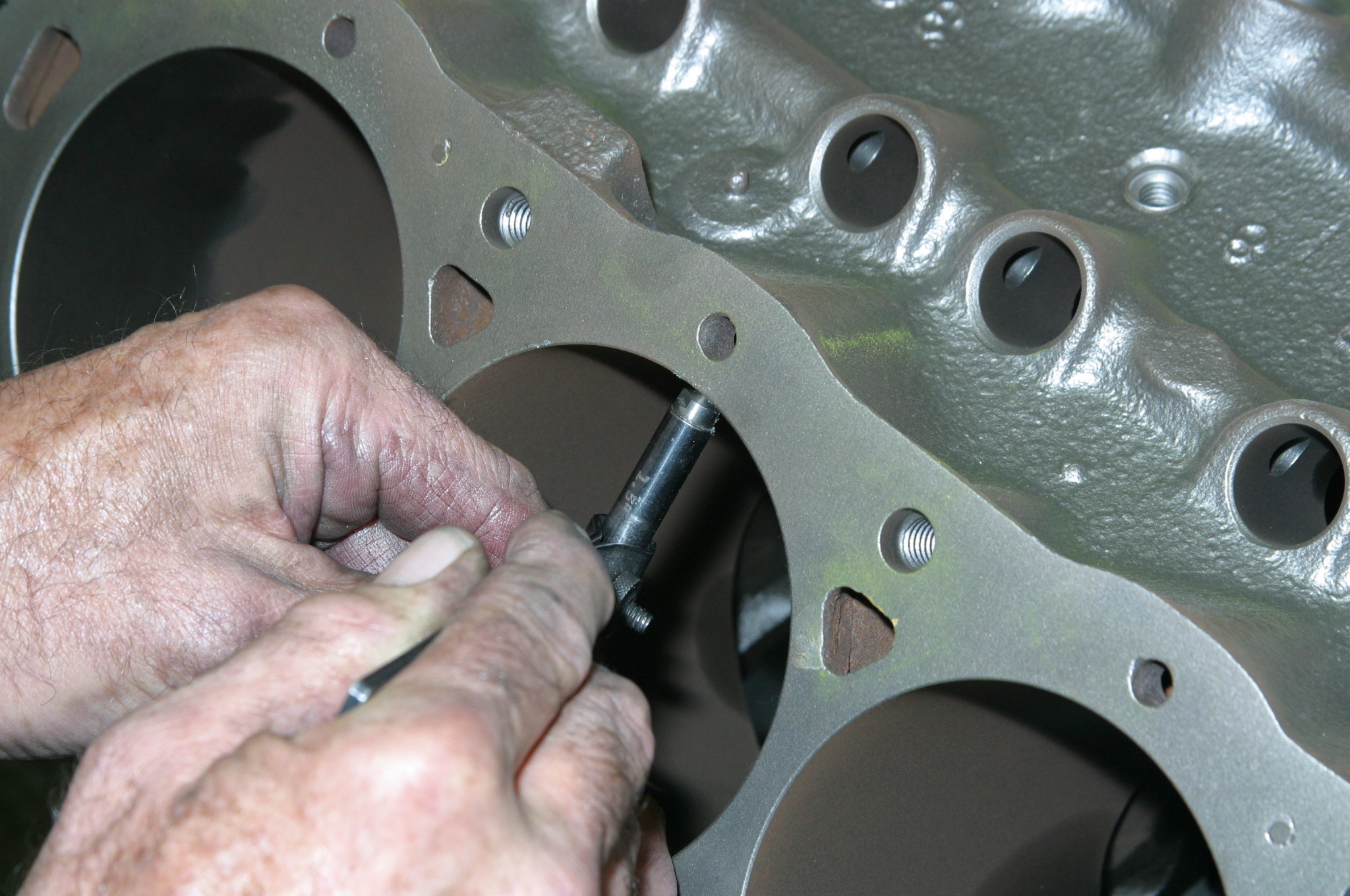
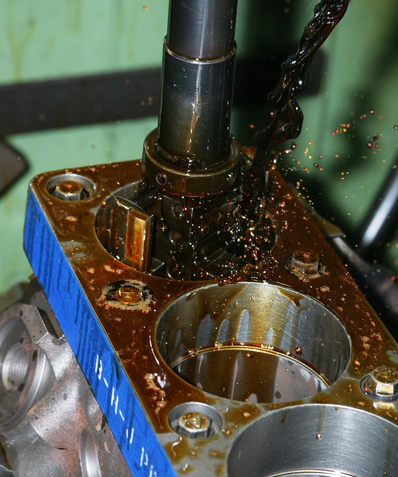
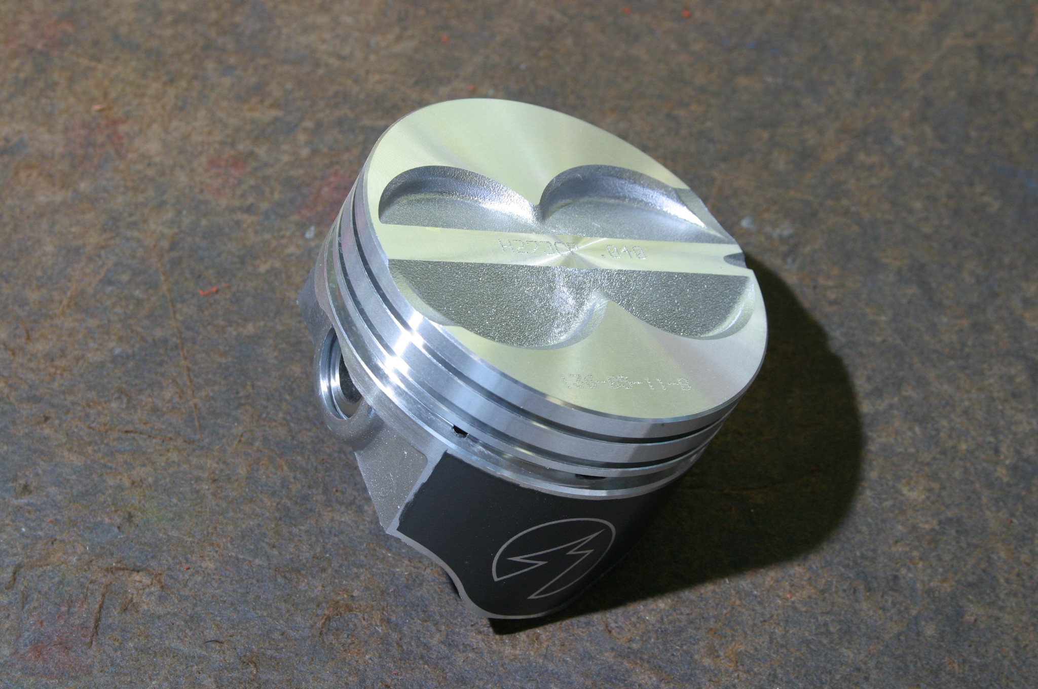
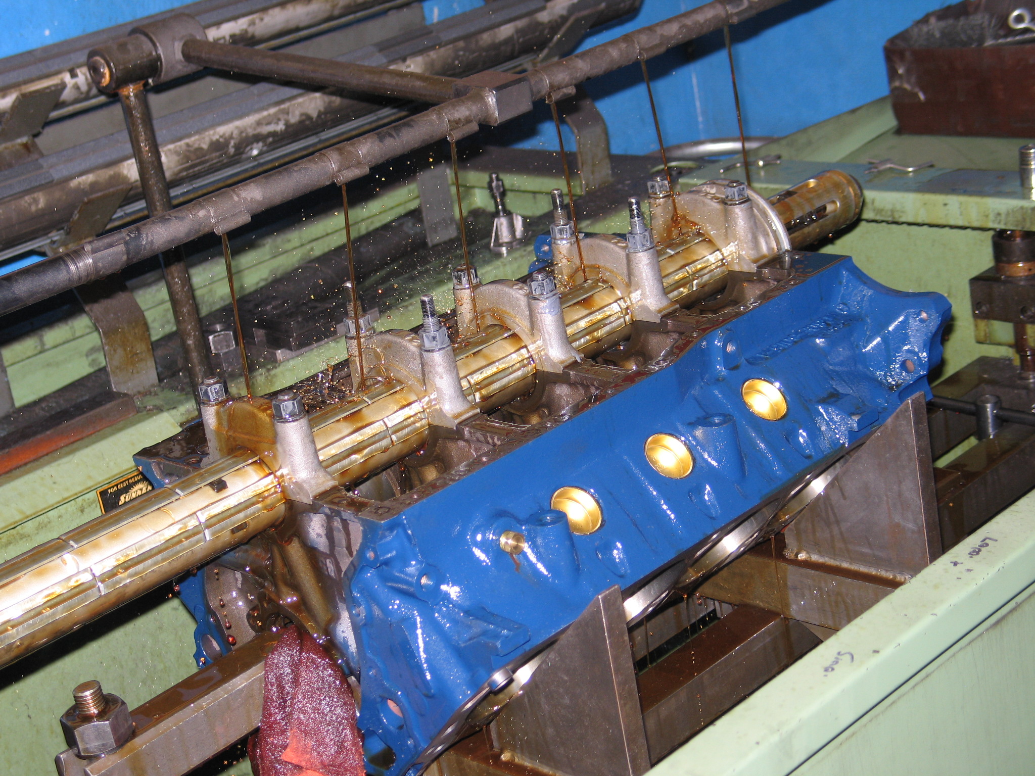
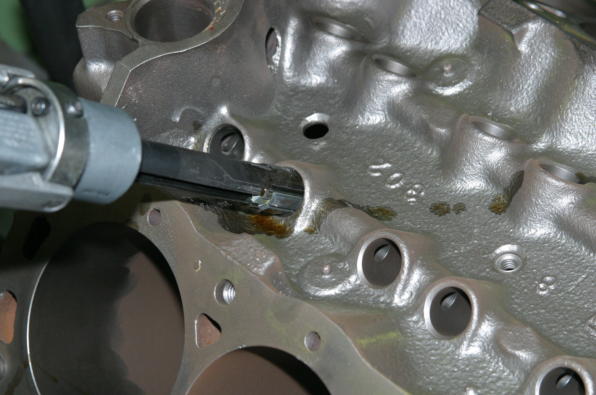
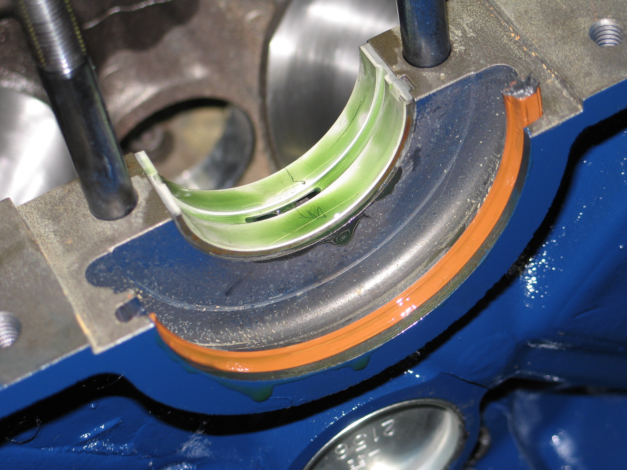
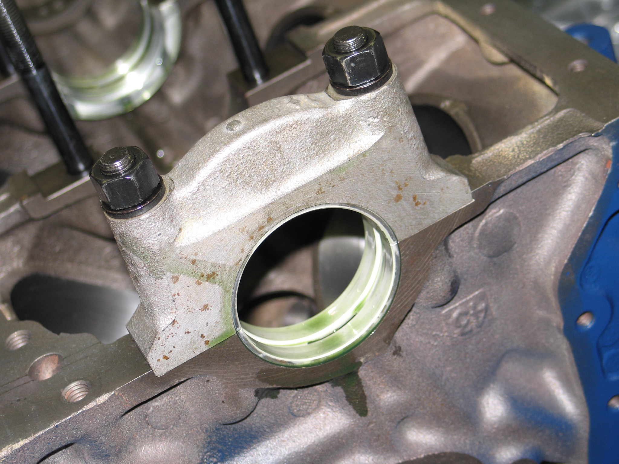
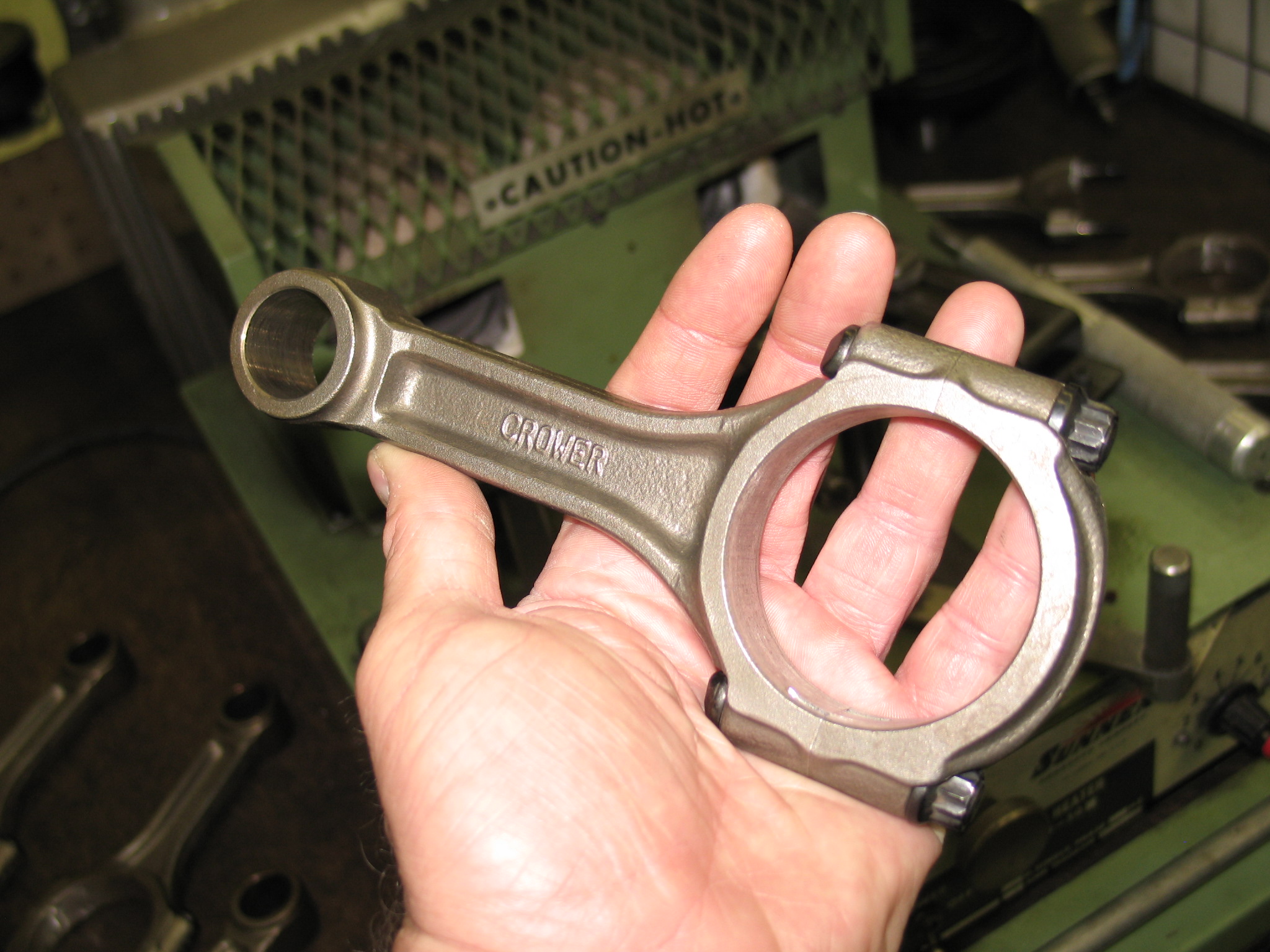
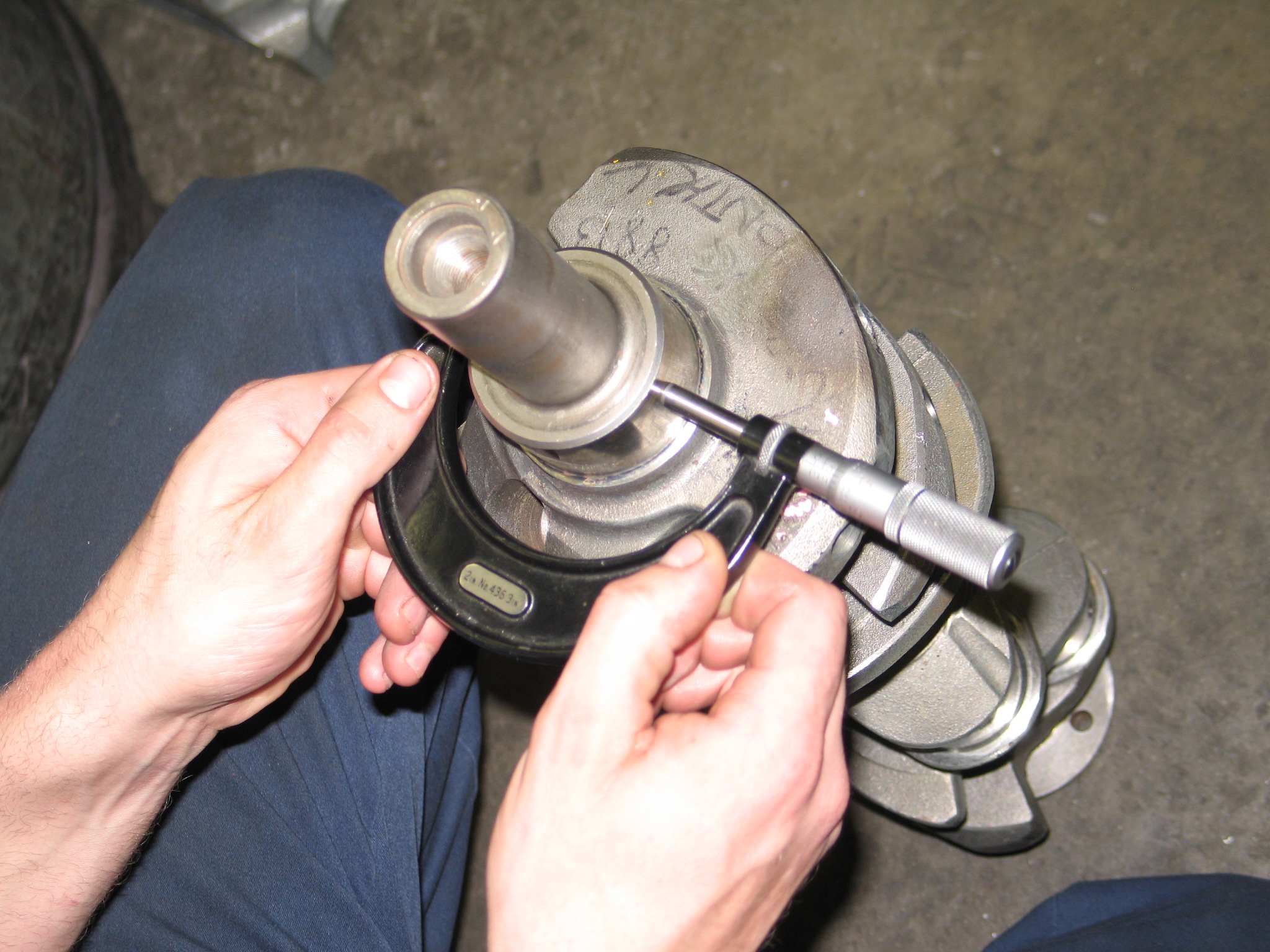
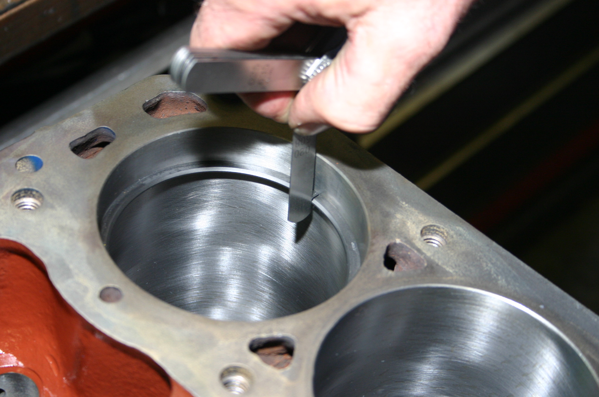
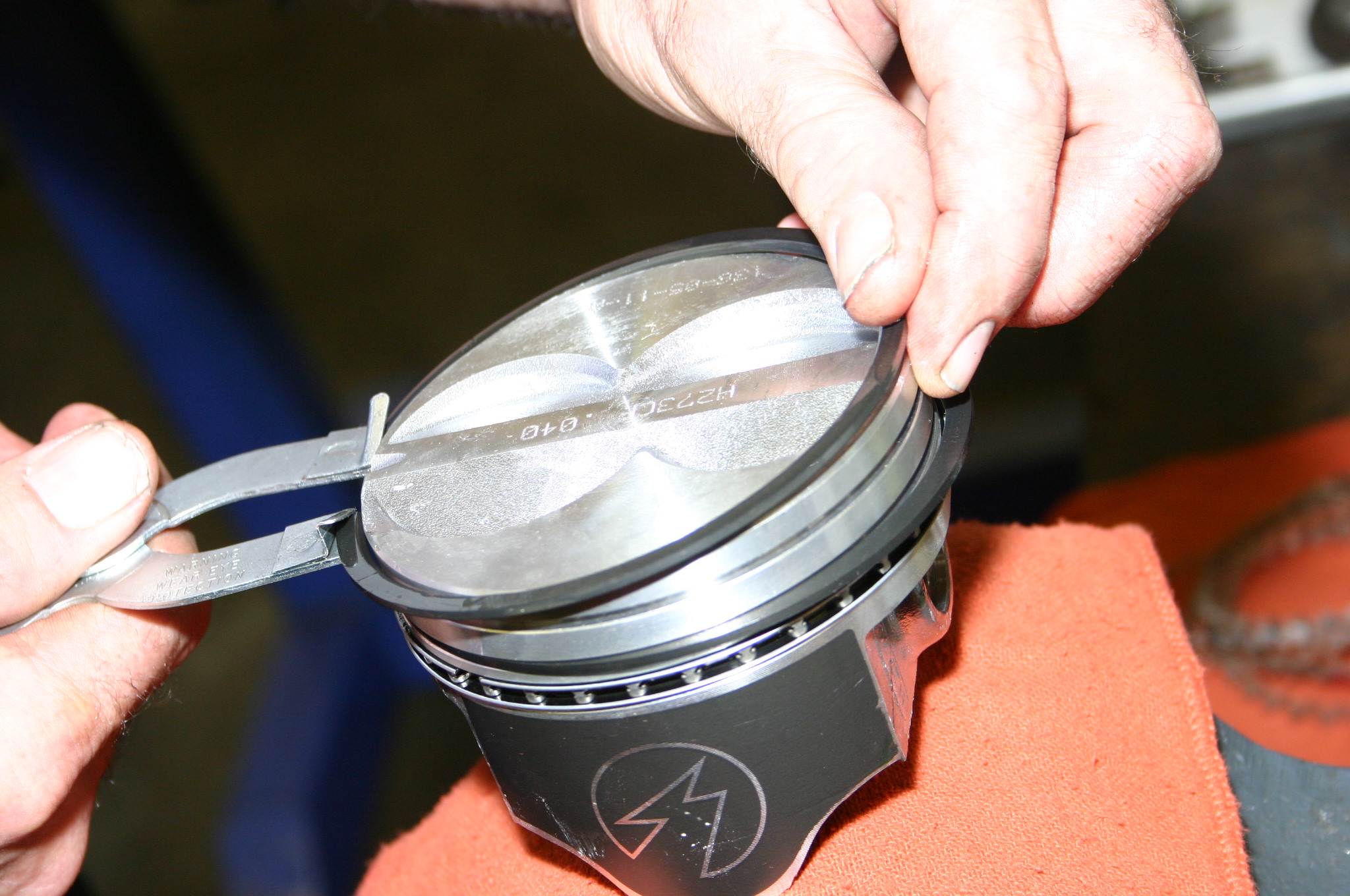
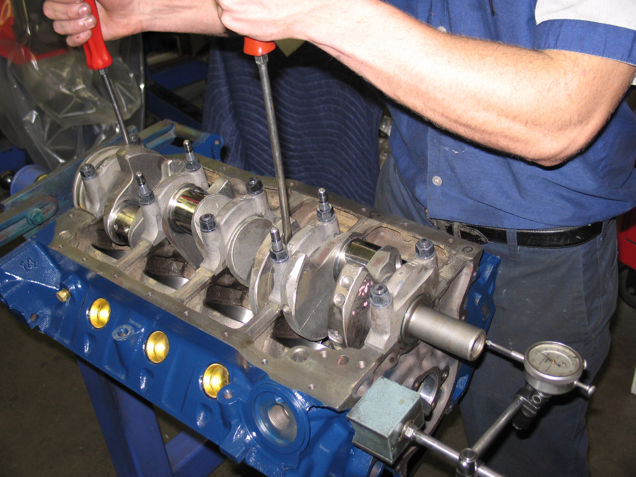
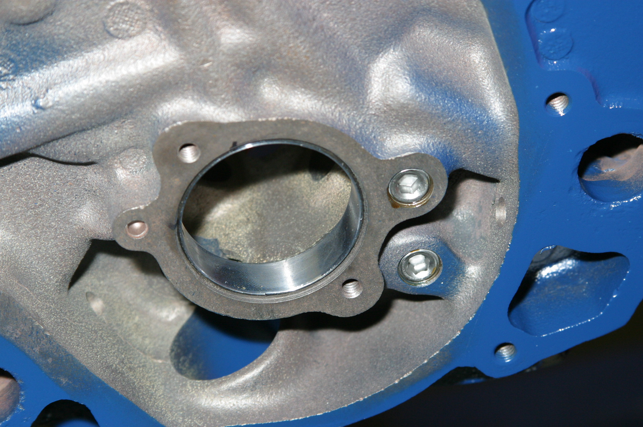
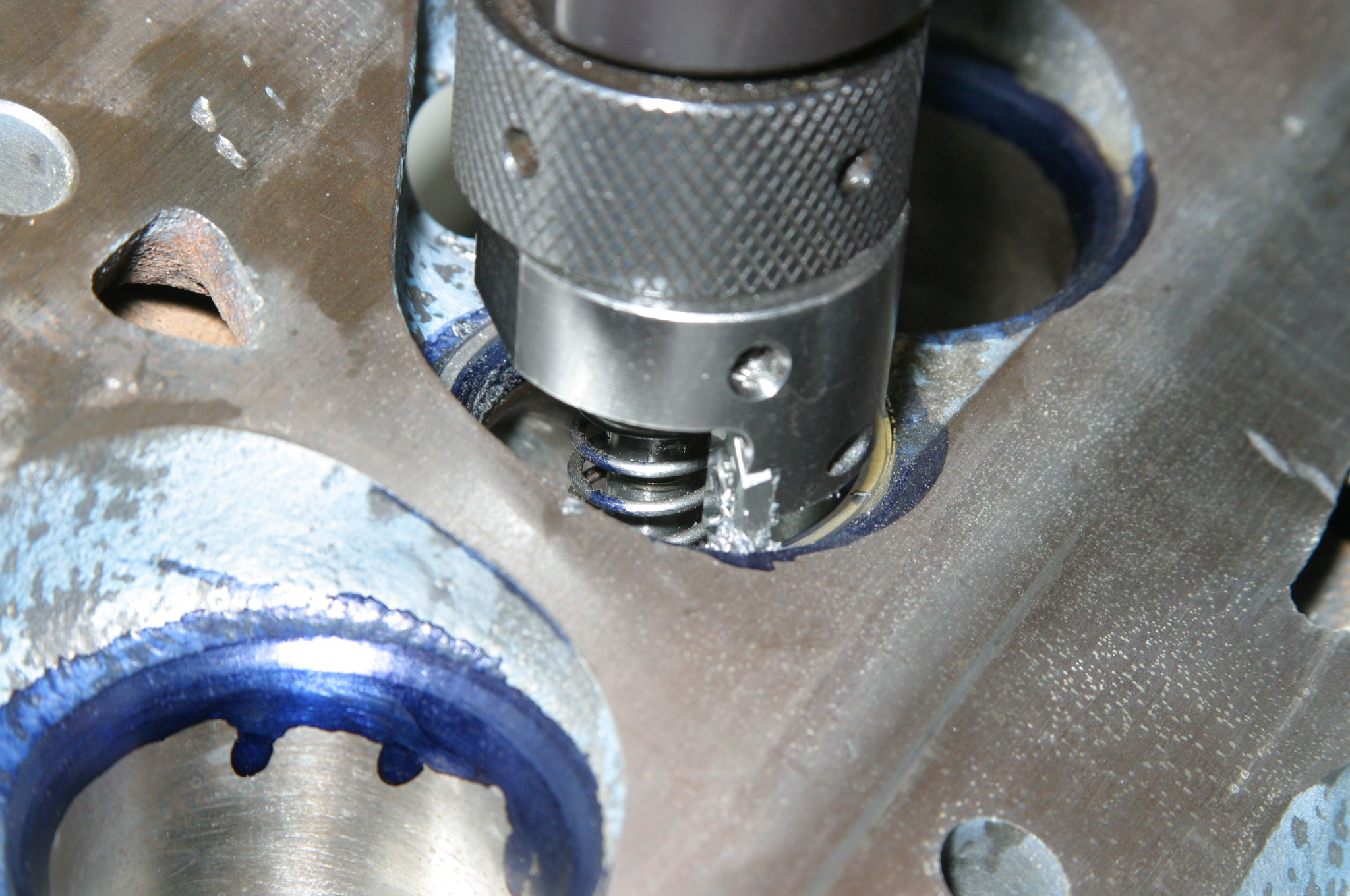
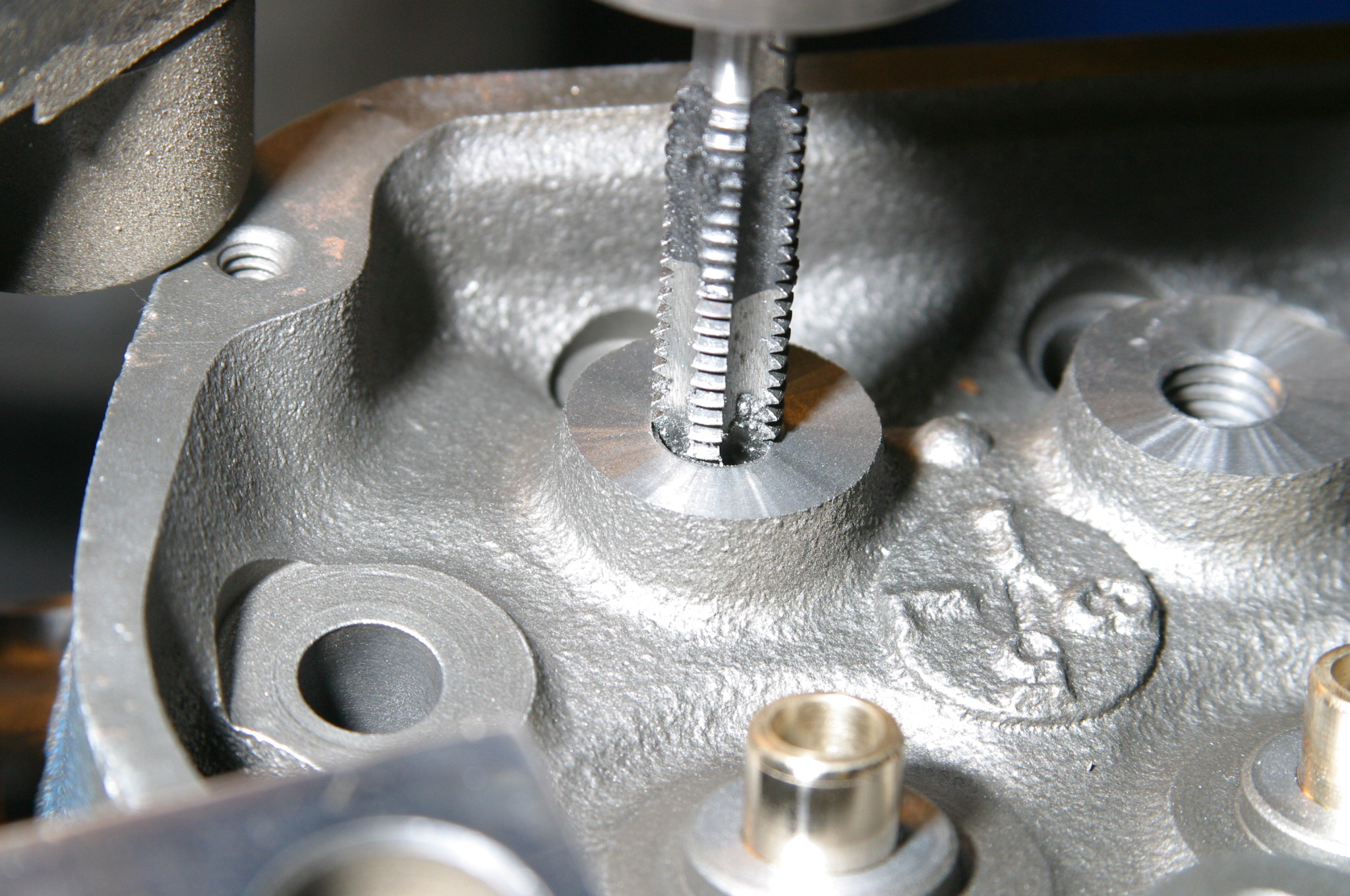
Our 289 had its share of operational issues, which called for an immediate teardown to determine what had gone wrong in the previous build. We’re at JGM Performance Engineering for a forensic look at what’s going on inside. (Image/Jim Smart)This is an unusually early 1968 302 block factory assembled as a 289. The 302 block has slightly longer cylinder skirts to accommodate the 302’s 0.013-inch longer stroke. The “7F29” casting date code means June 29, 1967 at Ford’s Cleveland foundry. The “C8OE-6015-A” indicates a 302 block. (Image/Jim Smart)Cylinder bores milled larger than acceptable for a 4.030-inch bore with excessive piston-to-cylinder wall clearances. JGM had to go 0.040-inch over to clean them up. (Image/Jim Smart)Cylinder walls cleaned up at 4.040-inch with a nice crosshatch finish hone. (Image/Jim Smart)JGM ordered a set of Speed Pro hypereutectic and coated pistons from Summit Racing, which were in stock and ready for delivery. (Image/Jim Smart)When JGM checked the line bore, it had suffered from poor machine work, which called for a fresh align hone to get the main saddles back where they belong. (Image/Jim Smart)JGM honed the lifter bores to both improve tolerances and get oil control in check with a good crosshatch pattern. (Image/Jim Smart)This is the Fel Pro FEL-2901 Performance two-piece rear main seal for the Ford 289/302 (prior to 1982). Builders all have their own approaches to installation. JGM likes to stagger seal ends to keep them away from main cap-to-block seams. Put a dab of Permatex’s The Right Stuff at each end. Did you know you can turn a two-piece rear main seal into a one-piece? Ask your machine shop about this. (Image/Jim Smart)Even if you’re building a stocker, opt for ARP main studs for added main cap security. (Image/Jim Smart)Although the stock Ford rod reconditioned with ARP Wave-Loc 3/8-inch bolts can withstand upwards of 400 to 500 horsepower, Crower I-beam Sportsman rods give you an added measure of protection. The previous builder opted for the Crower connecting rods. (Image/Jim Smart)JGM mikes the main and rod journals, which have already been turned .010-inch under. Journals look good, have been micro-polished, and are ready for a return to service. Everything has been dynamic balanced. (Image/Jim Smart)Piston ring end gaps must always be checked even if you have a set of pre-gapped rings. With our 4.040-inch bore times 0.0045—ring end gaps should be 0.018-inch. If you’re running mild boost no greater than 15 pounds, 0.022-inch. (Image/Jim Smart)There’s always the endless debate regarding piston ring installation—rolling on versus using an expander. As long as you don’t distort the rings, either approach is acceptable. The minute you distort the ring, it becomes scrap iron. (Image/Jim Smart)We’re running a Comp hydraulic roller cam (31-412-8) with 0.480/0.480-inch valve lift and 260/260 duration at 0.006-inch on 110 lobe centers for good street torque (300 lbs./ft.) and 320 horsepower at 6,000 rpm. The journals and lobes need Comp Cams engine assembly lube (not molybdenum-zinc) on the journals and lobes. This is a good street/strip cam with good low-end torque. (Image/Jim Smart)Crankshaft endplay is checked before anything else is installed. Endplay should be 0.004 to 0.008-inch. Closer to 0.008-inch if you’re running a lot of power. We opted for ARP main studs for solid security. There’s always the option of a main stud girdle for rigidity. (Image/Jim Smart)From the factory, Ford uses press-in oil galley plugs. JGM taps these galleys and installs screw-in plugs. (Image/Jim Smart)Our completed 289 short block is ready for heads, Melling high-volume oil pump with ARP shaft, baffled front sump pan, timing cover, heads and induction. Note the dual-roller timing set with an oil slinger. Do not use the Ford oil slinger with a dual-roller timing set. (Image/Jim Smart)
Cylinder Head Work
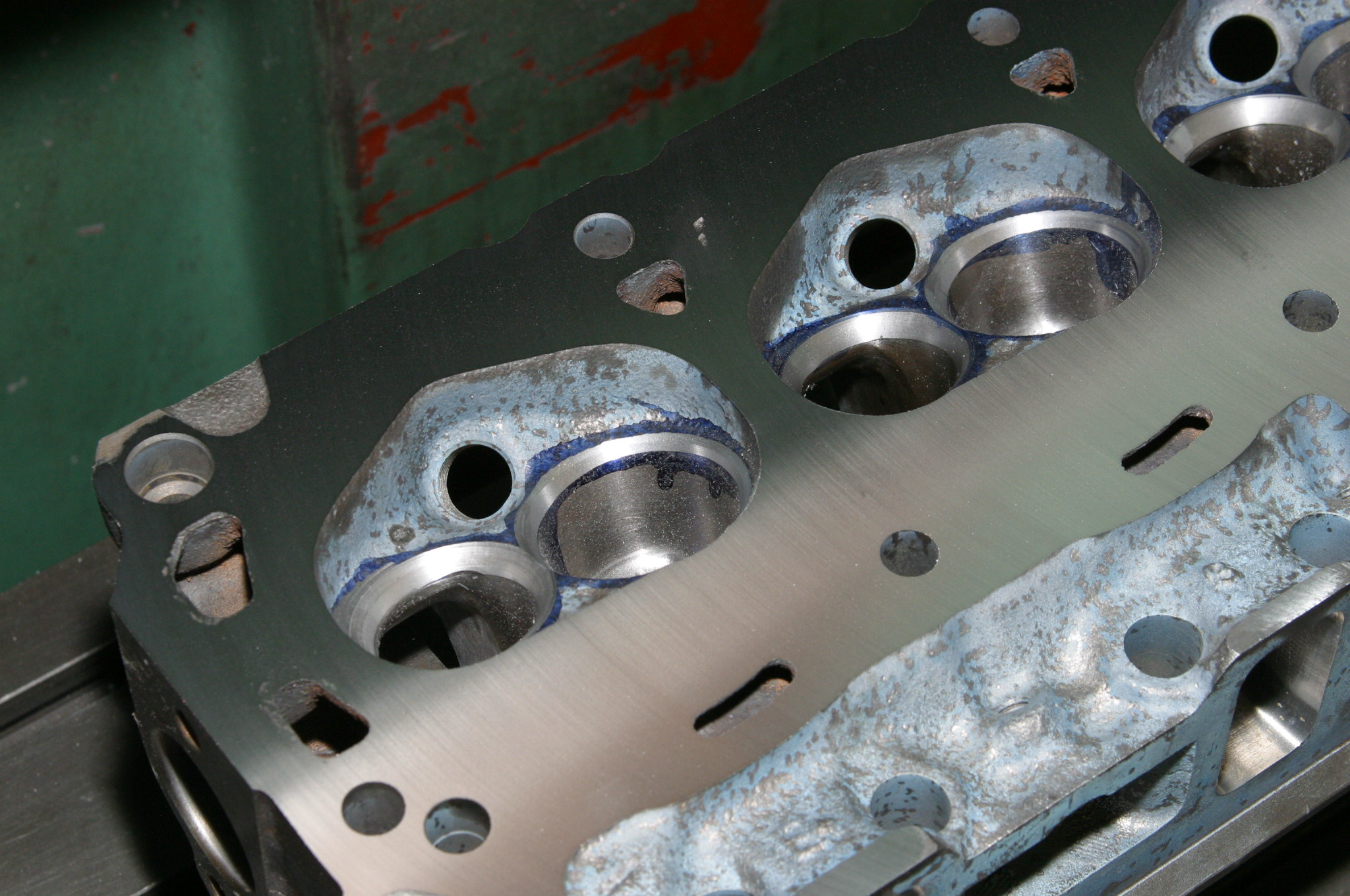
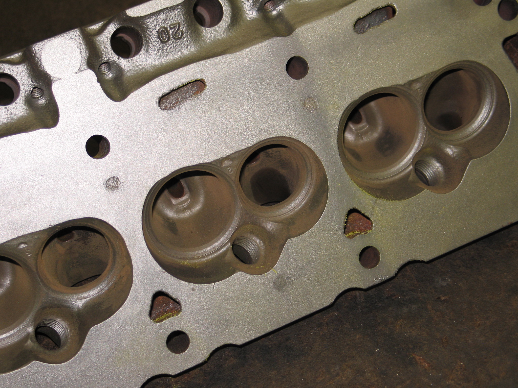
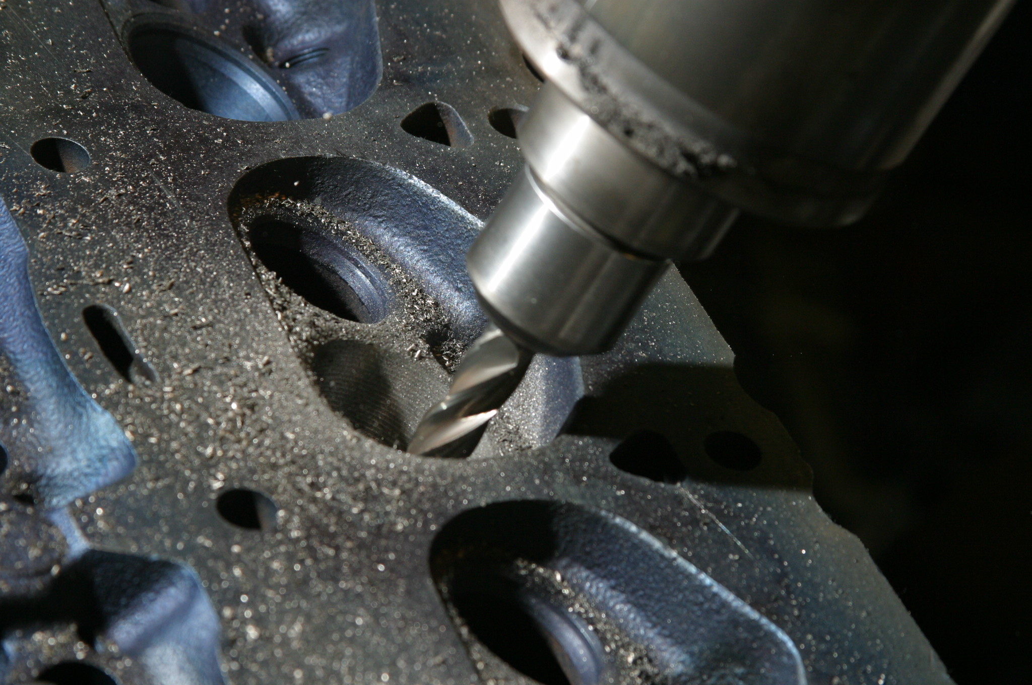
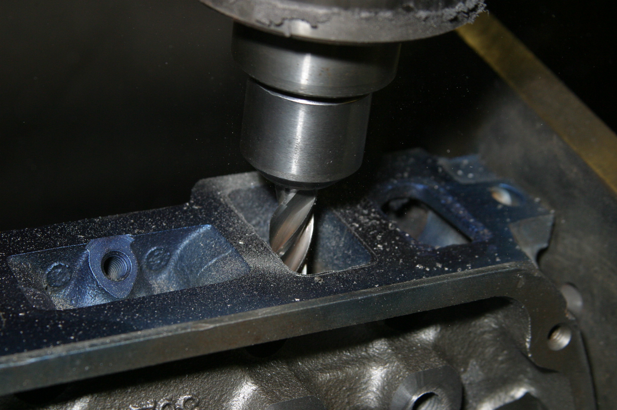
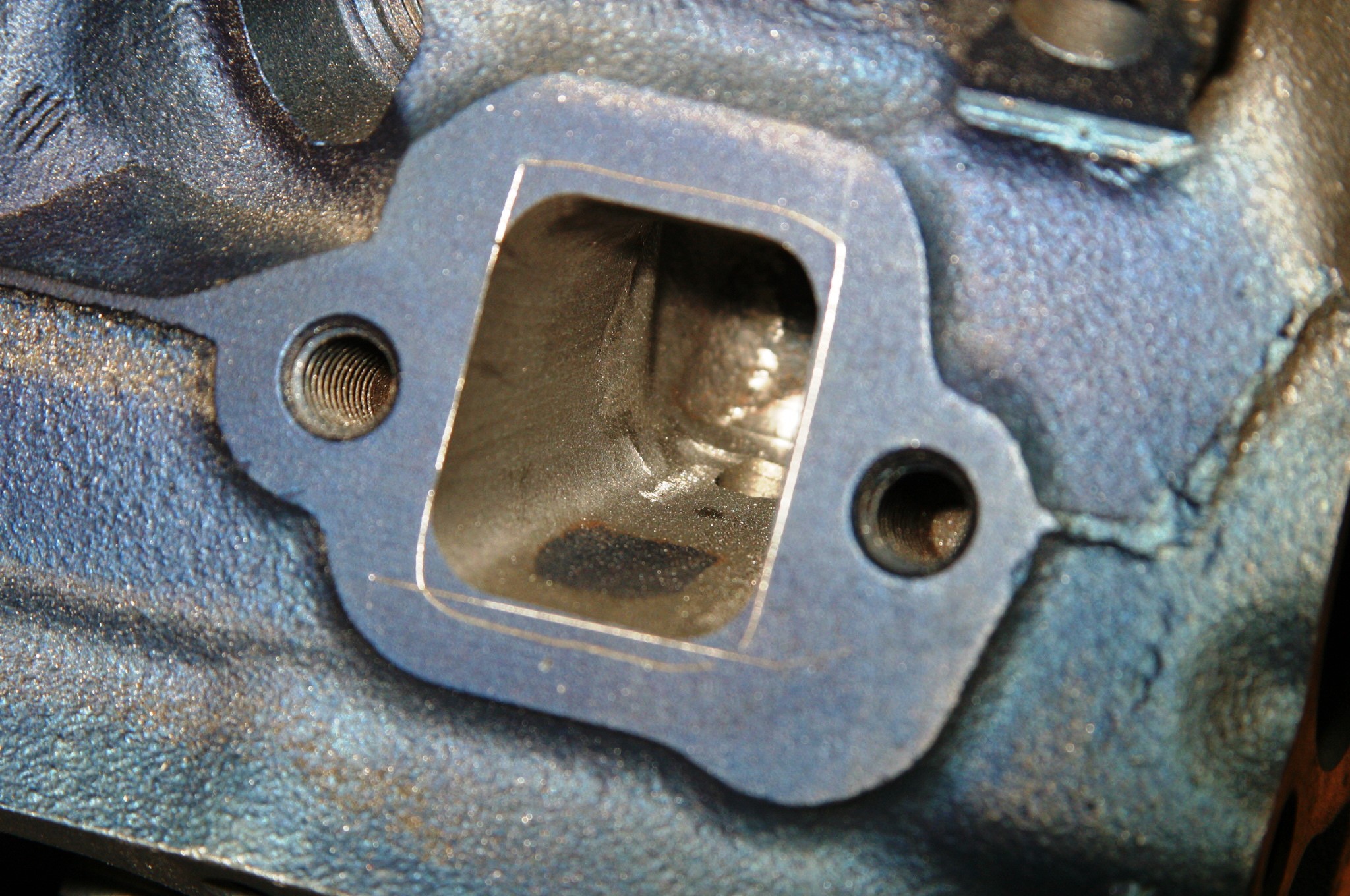
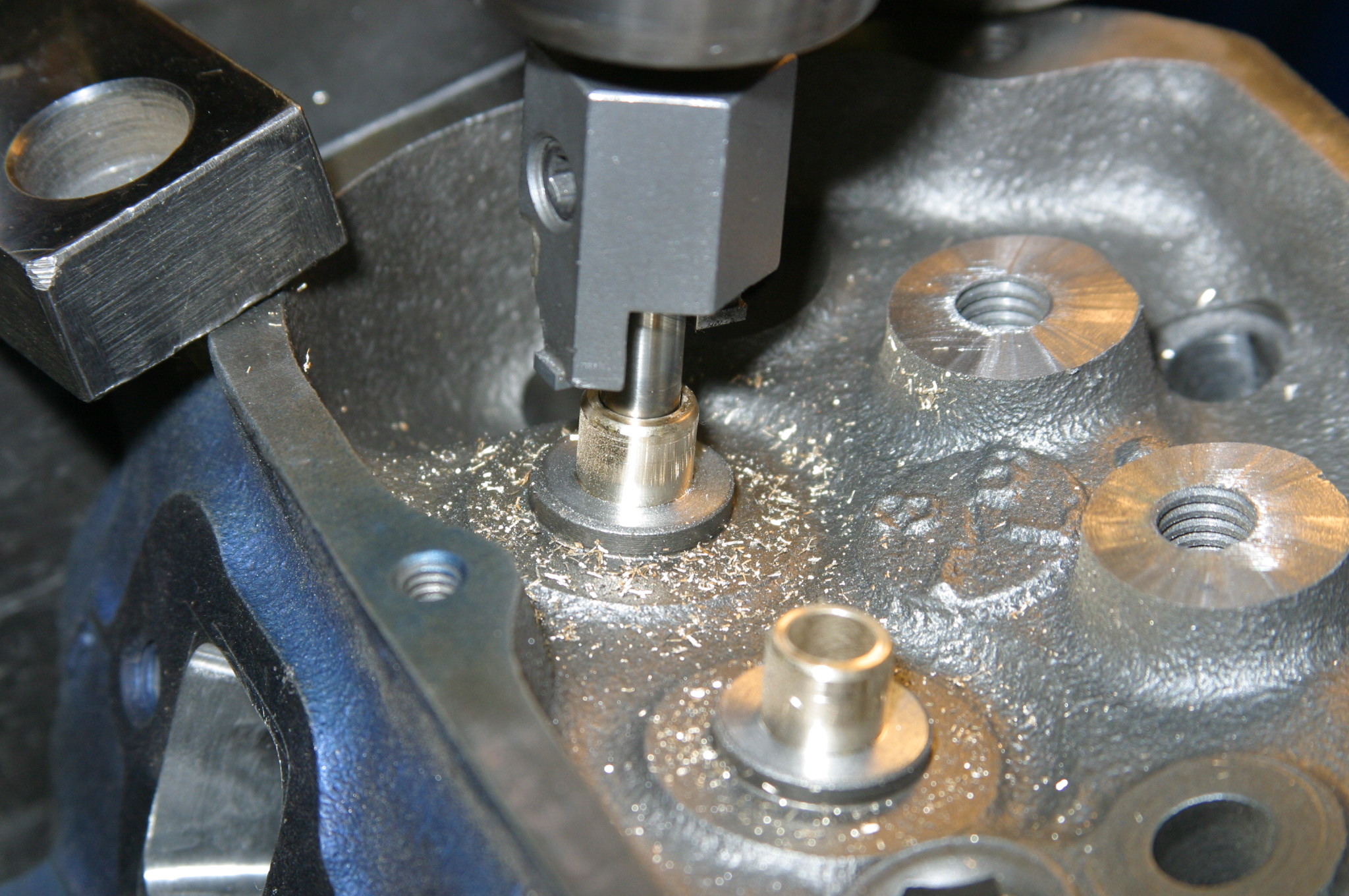
We opted for these C9OE 302 truck heads with 64cc chambers from Mustangs Etc. in Van Nuys, California, which will be ported for improved flow. The optimum Ford cylinder head to use is the early (1969-71) 351W head or the mid-1960s 289 head with 53 or 57cc chambers to get the compression. Ford never made a great small-block cylinder head because port sizing was always too conservative. (Image/Jim Smart)The 1969 302 truck head sports 64cc chambers, which makes them conservative compression wise. We’ve had CNC port and bowl work performed on these castings, which will improve flow. They have been milled .010-inch to improve compression. (Image/Jim Smart)This is the smaller 53cc chamber found with both the 289 High Performance head casting and the super rare 1968 302-4V head, which is virtually impossible to find. These petite chambers yield plenty of compression and exceptional quench. (Image/Jim Smart)Port work begins with precision CNC machine work, which does the initial cutting, then, hand-massaged port work. (Image/Jim Smart)Once bowl work is complete, intake and exhaust ports get the primary cut, then, hand-porting finish work. The question to be asked here is—do you rework stock heads or invest in Trick Flow aluminum heads. Trick Flow heads yield all the improvements you want in a cylinder head, for roughly the same amount of money as port and bowl work on a factory casting. Because they are aluminum and dissipate heat better than iron, you can cheat and run more compression. (Image/Jim Smart)Exhaust ports have been opened up, which improves exhaust scavenging. Remember—exhaust flow is just as critical as intake flow. Ford heads suffer from limited exhaust flow from those tiny ports. This is what hinders power at high rpm. (Image/Jim Smart)You have two options when it comes to getting iron cylinder heads unleaded fuel ready. Your machine shop can cut the stock iron exhaust valve seats and install hardened steel seats. A money saver is the use of stainless steel valves from Summit Racing, which won’t harm iron seats and will wear well over time. (Image/Jim Smart)With new exhaust valve seats and guides, we’re ready for valve lapping and head assembly. (Image/Jim Smart)To get the compression up, JGM has decided to mill .010-inch off the head deck. This reduces chamber size and gets the head true. Sometimes, the manifold contact deck has to be milled to get it compatible with the intake manifold. (Image/Jim Smart)The 302 head’s stock press-in studs have been removed and are replaced with screw-in ARP rocker studs and Comp Cams guide plates. Pedestals have been milled the thickness of the guide plates. (Image/Jim Smart)Valve guides must be machined down for Viton valve seals. Those old rubber umbrella seals are old school. The Viton valve seals will last the life of the engine. (Image/Jim Smart)
Final Assembly
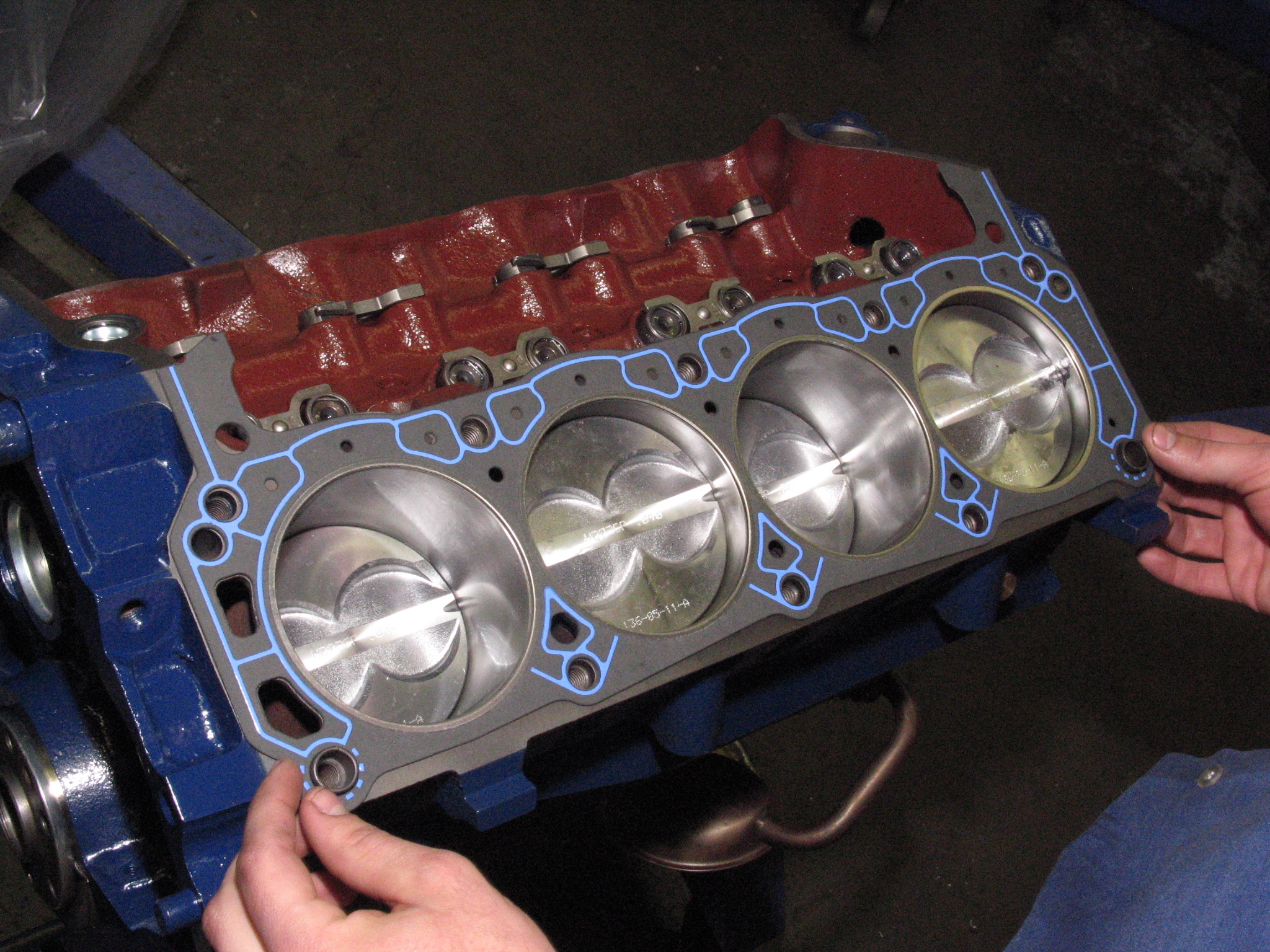
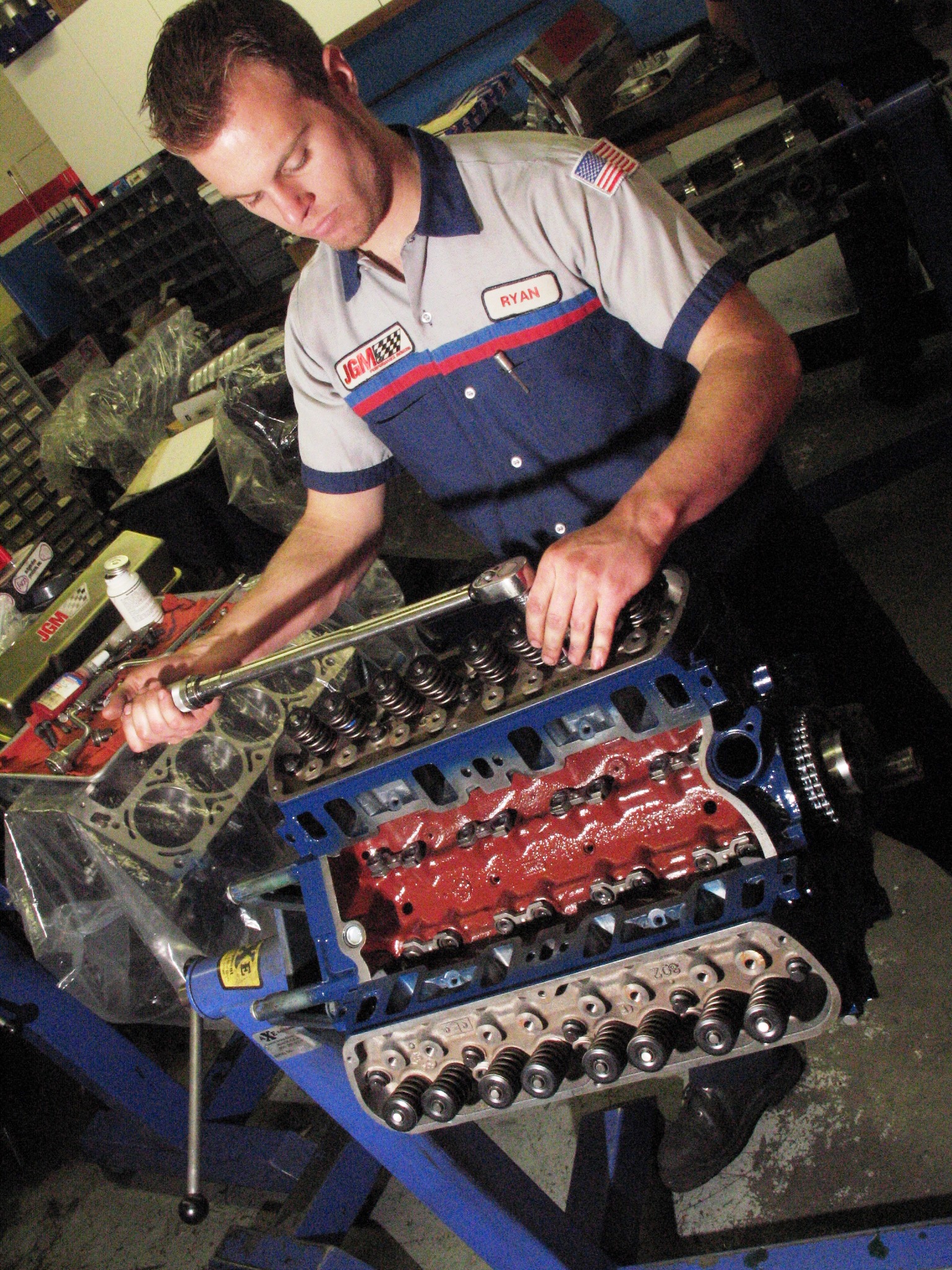
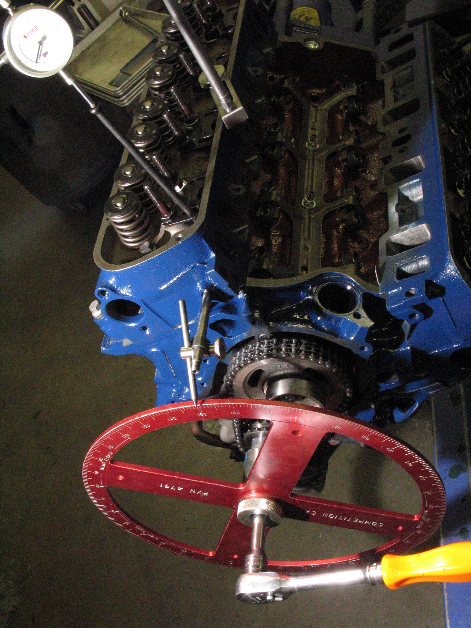
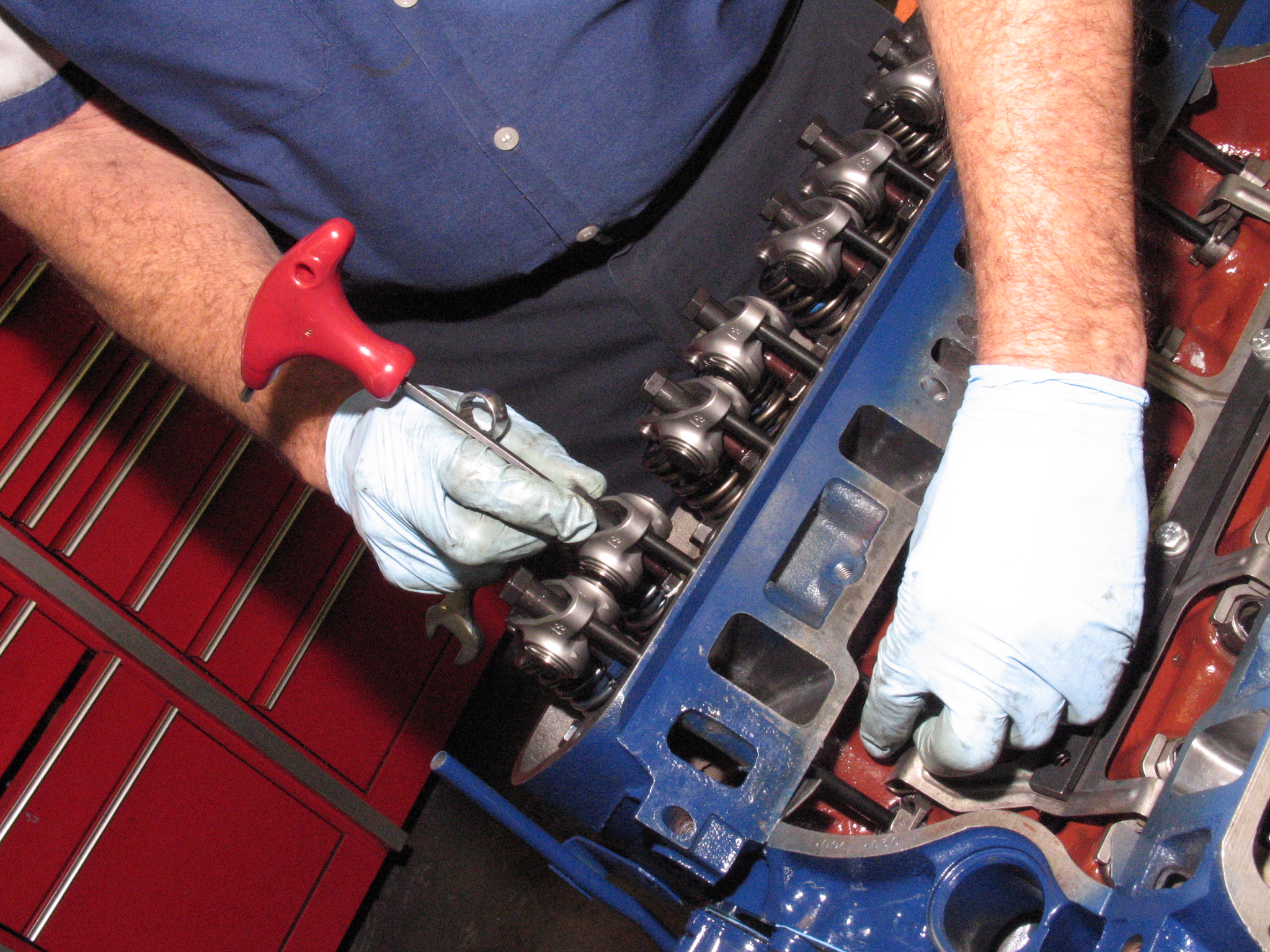
Fel-Pro’s Print-O-Seal cylinder head gasket is a nice affordable gasket for mild street and high-performance engines. We have used untold numbers of these head gaskets with great success. If you’re boosting or running nitrous, you’re going to need Fel-Pro’s PermaTorque® MLS head gaskets. (Image/Jim Smart)Few things are more important than hospital-clean mating surfaces and proper torque. Always follow Ford’s lead on the order tightened and torque values. Gently torque your head bolts in one-third values—65 to 72 ft./lbs. total. This means 24 ft./lbs. the first time, 48 the second round, and finally 72. Then, check your torque numbers on all fasteners. (Image/Jim Smart)We’ve opted for the spider retrofit from Comp Cams. You may also go with linked roller tappets and eliminate the spider, which is your best choice. Use a thread locker on the spider fasteners. (Image/Jim Smart)Although we’ve already installed the cylinder heads, it is best to degree the cam before you install the heads. True top-dead-center on #1 cylinder must be confirmed first, or the entire process is a wash. Then, degree the cam and compare your findings with the Comp cam card and advance or retard valve timing accordingly. If you are stumped, consult with Comp’s tech professionals. (Image/Jim Smart)Engine builder Jeff Latimer has presented us with the best approach. Do valve lash adjustment one bank at a time—hand-crank the engine in its normal direction. Watch the exhaust valve on the cylinder you’re adjusting.
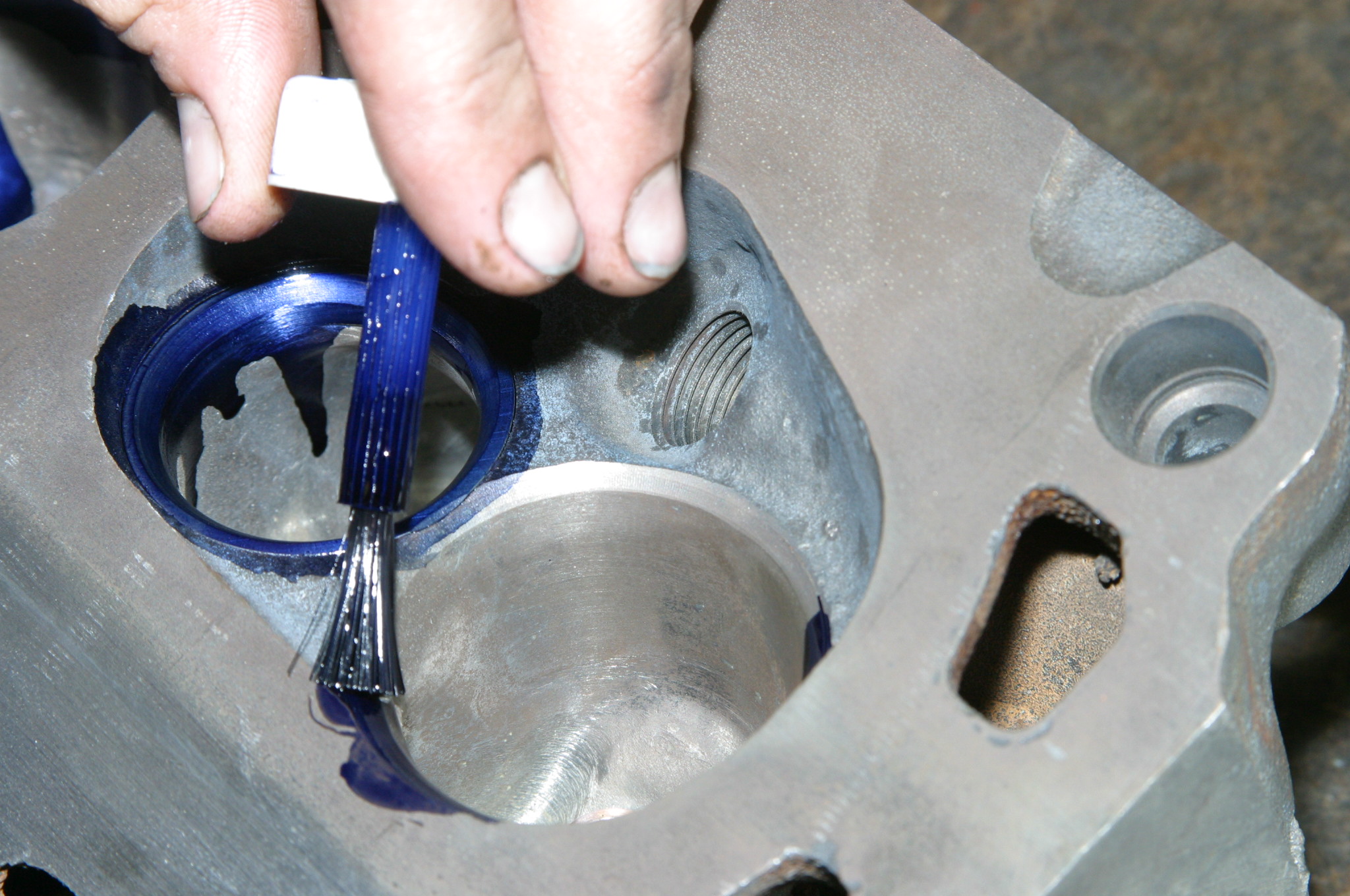
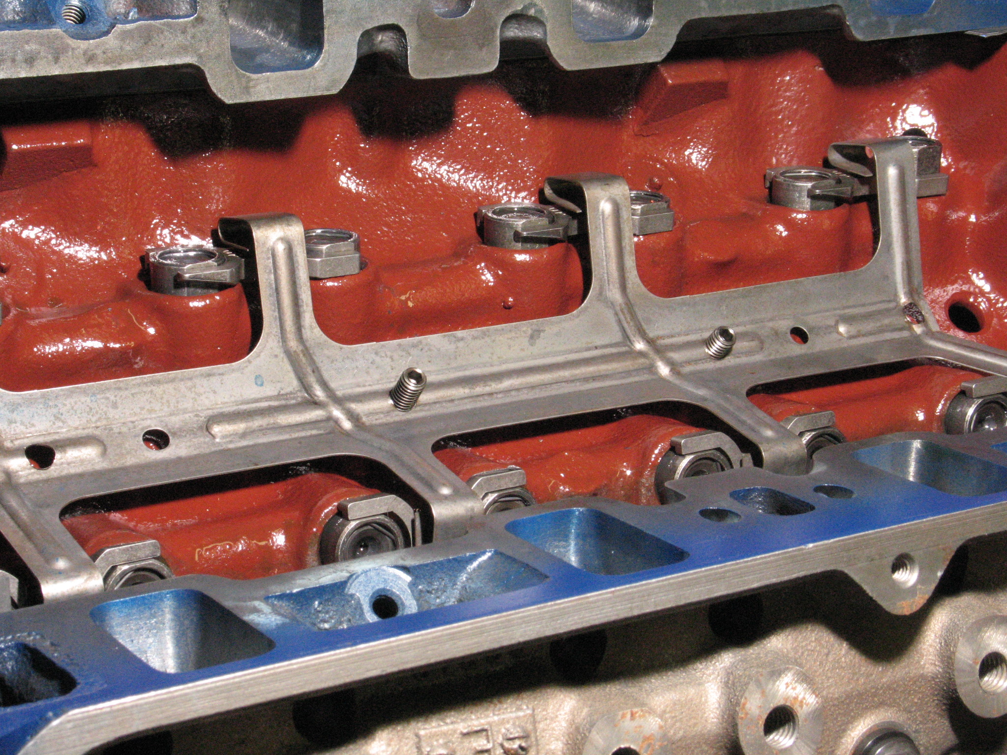
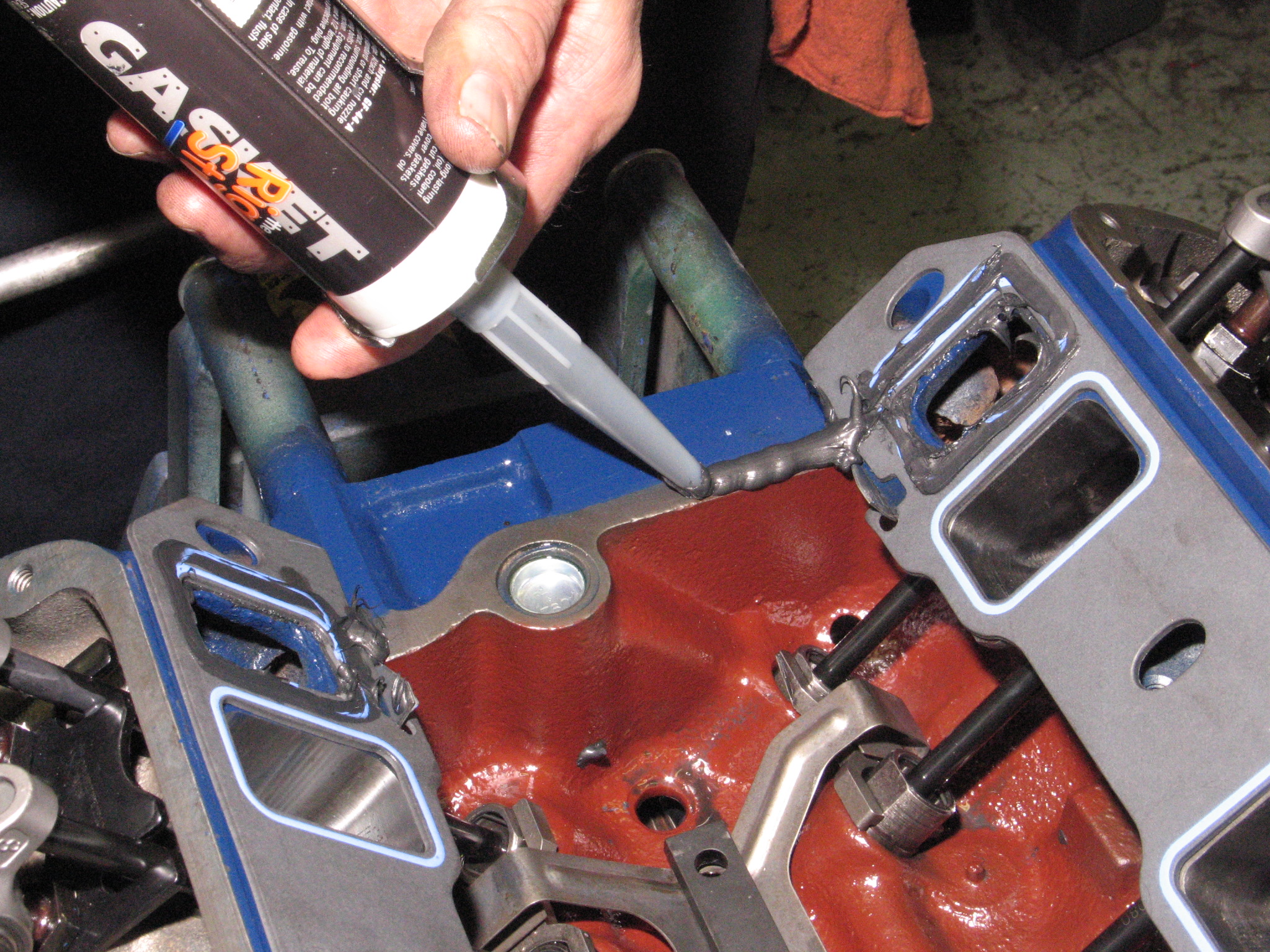
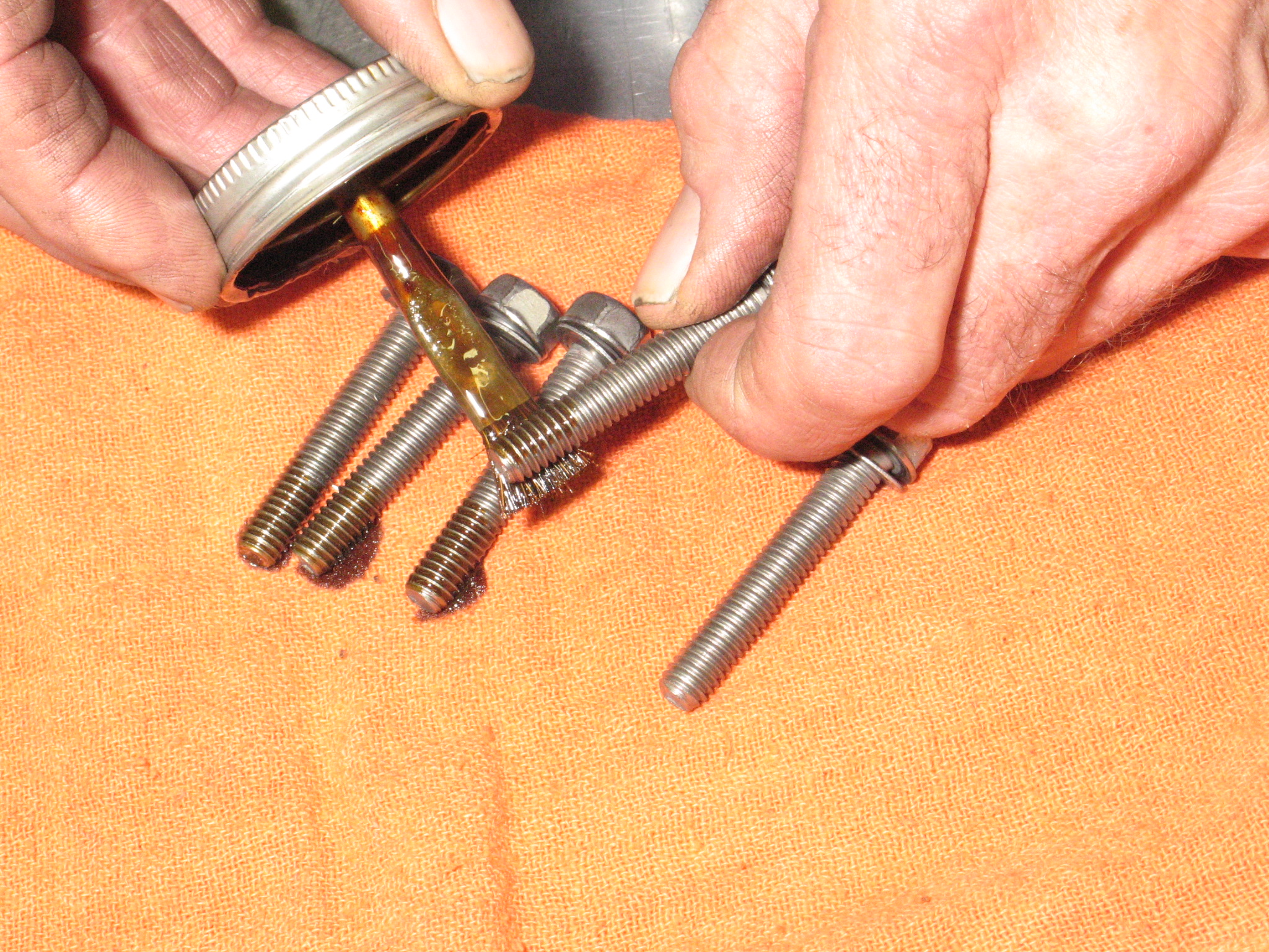
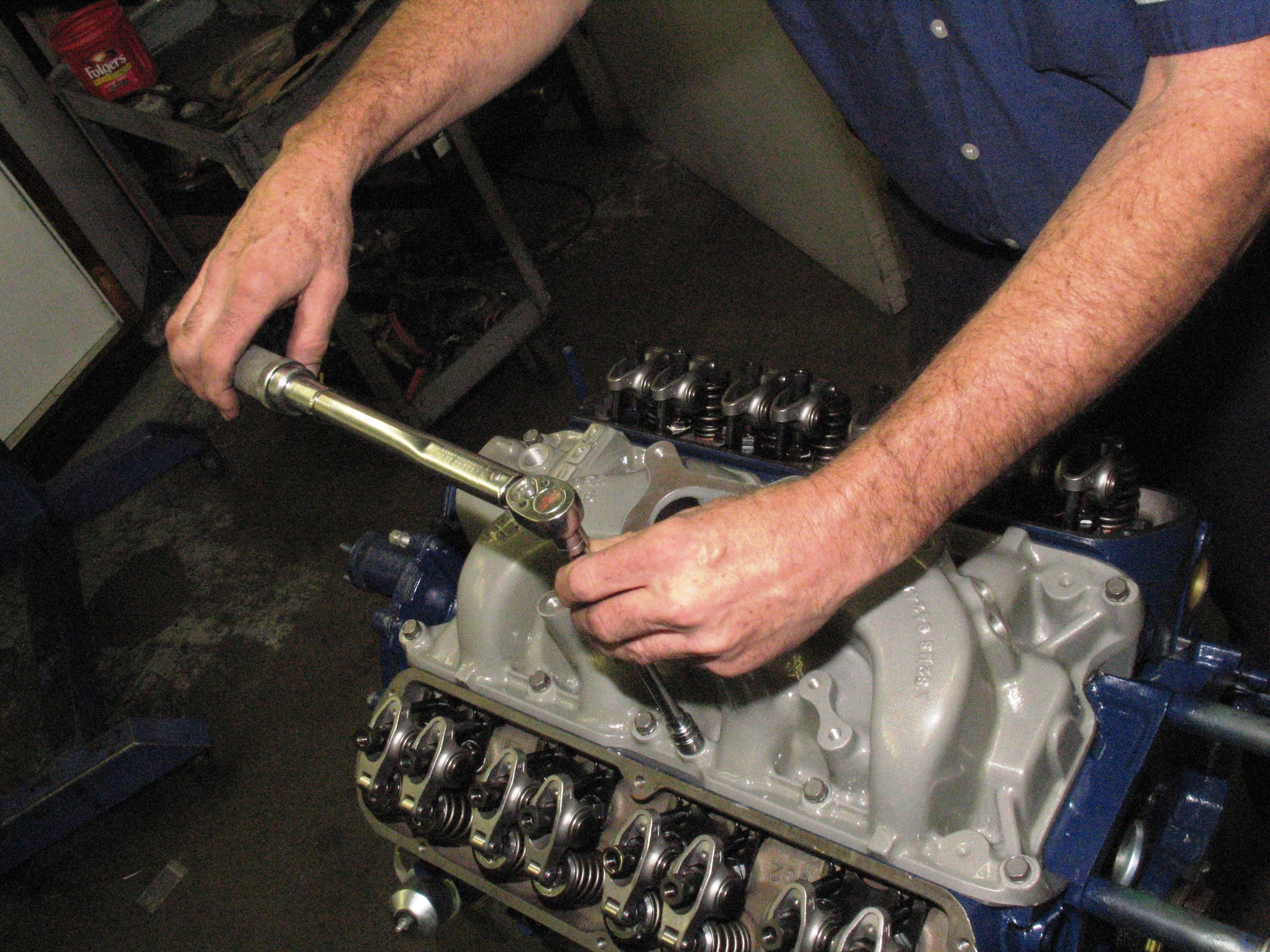
“When the intake valve is at maximum lift, adjust the exhaust valve lash,” Jeff comments, “Then, hand crank the engine until the exhaust valve is halfway to maximum lift. Adjust the intake valve lash. Please do not confuse thinking if the valve is open it is time to adjust the closed valve. Otherwise, you’re not on the heel of the cam lobe and your adjustment will be incorrect.” (Image/Jim Smart)One thing we see time and time again is excessive use of sealer where very little is required. Cooling passages call for a thin film of Permatex’s The Right Stuff. End rails depend upon how large the gap is. Be prepared to do a wipe down once the intake manifold is seated. (Image/Jim Smart)Intake manifold bolts should receive Permatex Form-A-Gasket to seal the valley and keep oil inside. Form-A-Gasket is old school, however, it works exceedingly well on bolt threads and areas requiring very little sealant. (Image/Jim Smart)Intake manifolds require very little torque—23 to 25 ft./lbs. in crisscross fashion in one-third values. Recheck the torque when you are finished and resist the urge to tighten the bolts any further. (Image/Jim Smart)
Jim Smart is a veteran automotive journalist, technical editor, and historian with hundreds of how-to and feature articles to his credit. Jim's also an enthusiast, and has owned and restored many classic vehicles, including an impressive mix of vintage Ford Mustangs.
Comments
7 responses to “Building Affordable Ford 289/302 Power!”
I am using 1965 289 heads 54cc 1.94 ans 1.60 valves. The heads have been milled.0i5. I think compression is close to 11 to 1. I have the heads on a 347 stroker. The cam is 488 lift 290 duration with solid lifters. We can only run a 500 Holly two barrel however we can run a cast iron 4 barrel I am running a 1865 4 barrel. Stock exhaust.Can you give me a guess on my horsepower ?
How Much do these ford motors cost to build..I’m really thinking about putting a 350(400hp) on t.it..They are much cheaper to build and I can make it fit..But how much would the 302 cost to build?
Gotta remember the way they rated output in the old days was without accessories on ,measured at the flywheel. Now, all the accessories are on and some are measured at the back of the transmission.
JIM PLEASE ADVISE ON A RETRO ROLLER CAM FOR A 289 – TO GET TO THE 300 OR 320 HP YOU MENTION.
CRANE , ISKY , COMP? NERVIOUS ON FLAT TAPPET HAVE HEARD MANY BAD STORIES ON QUALITY OF BILLET, AND ALSE SEVERE WEAR IN RUNNING IN – EVEN WITH LUBE. STEVE


I am using 1965 289 heads 54cc 1.94 ans 1.60 valves. The heads have been milled.0i5. I think compression is close to 11 to 1. I have the heads on a 347 stroker. The cam is 488 lift 290 duration with solid lifters. We can only run a 500 Holly two barrel however we can run a cast iron 4 barrel I am running a 1865 4 barrel. Stock exhaust.Can you give me a guess on my horsepower ?
How Much do these ford motors cost to build..I’m really thinking about putting a 350(400hp) on t.it..They are much cheaper to build and I can make it fit..But how much would the 302 cost to build?
275
I have 1985 302..But it was rated at 140hp..I want to get it up to 325hp..For my 2011 Ford F150..
Gotta remember the way they rated output in the old days was without accessories on ,measured at the flywheel. Now, all the accessories are on and some are measured at the back of the transmission.
JIM PLEASE ADVISE ON A RETRO ROLLER CAM FOR A 289 – TO GET TO THE 300 OR 320 HP YOU MENTION.
CRANE , ISKY , COMP? NERVIOUS ON FLAT TAPPET HAVE HEARD MANY BAD STORIES ON QUALITY OF BILLET, AND ALSE SEVERE WEAR IN RUNNING IN – EVEN WITH LUBE. STEVE
Hey Steve, you might want to check out this article by veteran automotive journalist Jeff Smith. He dispels a lot of the myths surrounding the alleged problems with flat tappet cams.