


Engines produce vacuum, and over the past 120 years, engineers have contrived ingenious ways to harness its power to the engine’s induction system. Through a labyrinth of small-bore drillings in the carburetor, the vacuum draws a potent mixture of air and fuel. So formidable is the mixture, it empowers naturally aspirated full-bodied 500-cubic-inch race cars to speeds in excess of 213 miles-per-hour in a distance no greater than 1,320 feet!
Although its fumes ignite, gasoline won’t burn and produce energy in its liquid form. Instead it needs to be emulsified (mixed with air), atomized, (separated into fine particles) vaporized (transformed to a gaseous state) and compressed in order for it to produce energy.
That’s where the carburetor comes into play.
In Carb Tuning Tips, Part 1, we provided a brief overview of the carburetor, including some basic carburetor anatomy. In Part 2, Demon Carburetion helps us identify a few more chief components of the modular, square-bore carburetor, acquaint you with common problems that can arise, and tell you how to prevent them.
Basic Carb Function
The carburetor takes responsibility for the emulsification and atomization of fuel, while the vaporization occurs in the induction tracts. In addition, the carburetor must meet the air-fuel ratio requirements of the engine.
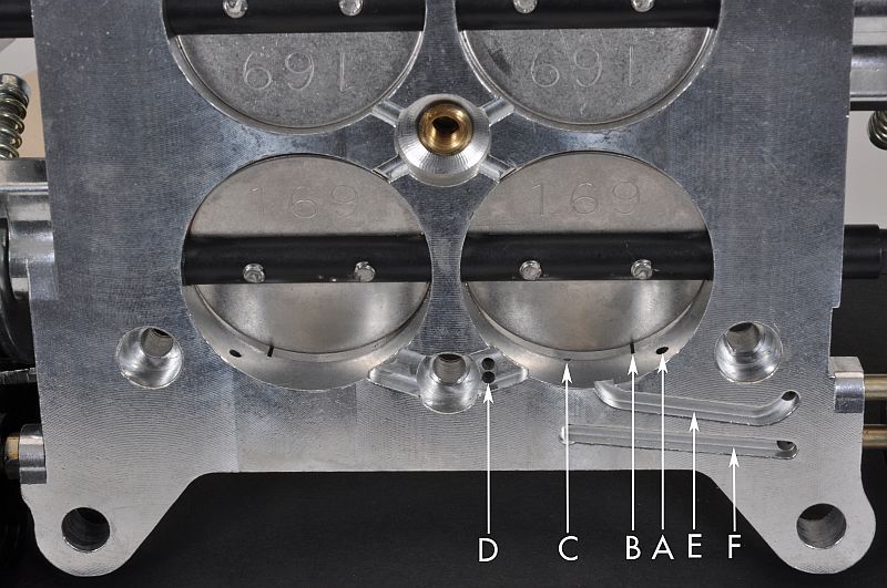
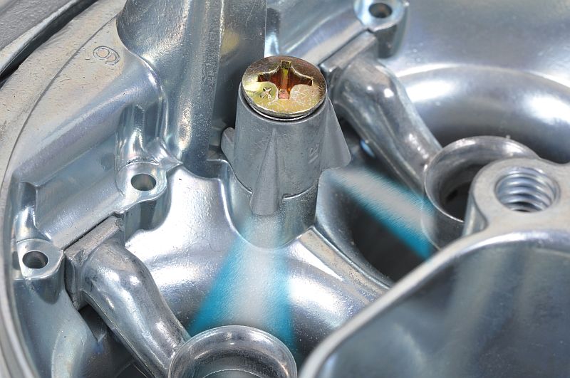
To emulsify the air and fuel, small-bore drillings are placed in the air entries on the top of the carburetor. They are known as air bleeds. The emulsified mixture is then drawn rapidly through a multitude of small passageways and distributed into the fast moving air stream in the carburetor’s throttle bores for atomization. It is discharged through a dozen small ports, three in each throttle bore. They are known as idle, transfer slot, and boost venturi.
The idle discharge ports and transfer slots are located in the throttle bores of the base plate and draw their source of fuel from the fuel bowls via the carburetor’s idle wells. The boost venturis and their discharge ports are positioned near the top of the carburetor and discharge into the narrowest part of the upper throttle bores. Boost venturis draw their source of fuel from the fuel bowls via the main wells.
The #1 Tuning Problem: Sloppy Idle-Speed Adjustment
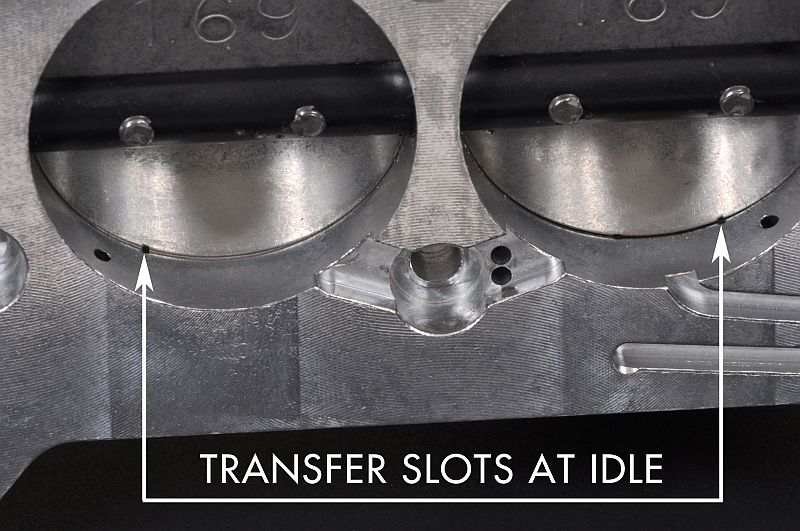
The top cause of carburetor troubles is the overexposure of the transfer slots at the idle condition. When increasing the idle speed of a four-barrel modular carburetor, adjust both the primary and secondary throttle blades. If you adjust the idle speed with the primary throttle blades only, you could upset their position relative to the transfer slots. Some of the adverse effects of an overexposed transfer slot at idle are hesitation, excessive richness, or poor running; it can even negate the idle circuit completely. In the idle condition, when the throttle blades are closed, the transfer slots should give the appearance of a small square when viewed from underneath the base plate.
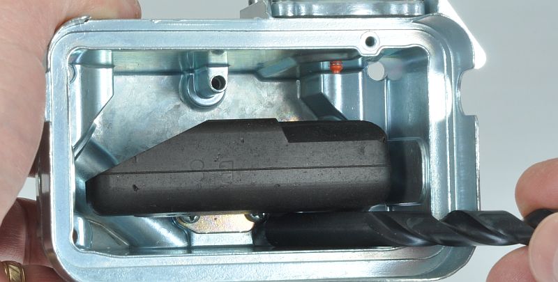
Demon Carburetion even created a special component to ease the complications associated with idle-speed adjustment. This device, known as Idle-Eze, can introduce an extra source of idle air to the engine without disrupting the critical relationship between the idle-speed adjustment screws, the throttle blades, and the transfer slots. The Idle-Eze has access to air above the throttle blades and can transfer it beneath them, if necessary. This introduces an extra source of air to the engine that can alter the idle speed by as much as 500 rpm without touching the idle speed adjusting screws.
Setting the Idle Mixture: Patience Pays Off
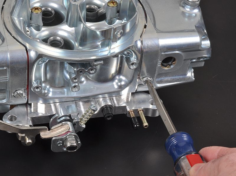
Set the idle mixture to the highest vacuum by using a vacuum gauge connected to the constant-vacuum port of the carburetor base plate. Slowly adjust the first idle-mixture screw. Make one adjustment only to the first screw. The adjustment should be no more than an eighth or quarter turn. Then leave sufficient time for the carburetor to respond and move to the next adjuster screw. Gradually work your way around the carburetor, making just one, small, slow adjustment to each screw.
Float Levels and How to Set Them
After setting the idle mixture, it’s time to check the float levels. With the motor running the fuel level should be in the middle of the glass window of the fuel bowl. If it isn’t, loosen the lock screw on top of the bowl and adjust the nut clockwise to lower the float level and counter-clockwise to raise the float level. Make the adjustment by one flat of the nut at a time and wait until the carburetor has had a chance to respond.
The ‘dry setting’ is accomplished by removing the fuel bowl and, with it turned upside down, set the dimension between the inside top of the bowl and the top of the float at approximately 0.375-0.0400 inches.
Pump Shooters (Squirters): Bigger Can Be Better
Installing larger pump shooters often eradicates a hesitation at off-idle, but frequently the fault lies not with the pump shooters at all but with incorrect ignition timing.
There are at least two ways of reaching the off-idle position, either gently or suddenly. If the throttle is eased into the off-idle position and the motor stumbles, the idle circuits and the transfer slots are probably too lean. To cure this condition, either slightly undo all four idle-mixture adjusting screws to enrich the system or enlarge the idle-feed restrictors in the metering blocks. On the other hand, if the hesitation occurs under rapid acceleration, increase the size of the pump shooters. The pump shooters only serve to provide the initial shot of fuel, and together with the idle circuits and transfer slots, they provide the predominant fuel supply to the motor until the main circuits are operating through the boost venturi.
The pump shooters are also particularly useful during cold starts. One or two depressions of the throttle pedal provide sufficient fuel for starting. A variety of orifices are available, ranging from 0.025-inches to 0.052 inches. Usually, larger engines use larger orifice pump shooters.
Air Bleeds: Big Risk, Big Reward
Replaceable high-speed air bleeds aid in tuning the fuel curve. These tiny bleeds work in conjunction with the main jets, emulsifying the air and fuel. The smaller the air bleeds, the richer the mixture, which is the opposite reaction when compared with main jets. As air bleeds are reduced in size, the carburetor draws more aggressively and adds additional fuel. But installing incorrect orifices in the air bleeds will bring you bigger trouble than their jet sizes. It pays not to touch them unless you have access to a dynamometer and can analyze the test results.
I have a Wonderful Wife!
With the primary transfer slots set, do you recommend adjusting idle with only the secondary plates? Well written article either way!
Assuming you have a progressive throttle linkage, and assuming your primary setting slightly exposes (primes) the transfer slot, then YES, use the secondary to adjust the idle speed as long as the adjustment is not excessive. You can jam the linkage by over adjusting the secondary. If you need lots more throttle opening (big cam), you should drill (4) holes on the outboard side of butterflies. Start with 1/8”. Or if you have an idle air bypass system (like the Holley XP) you don’t need to drill air holes. If you have a 1 to 1 linkage, you should set the throttle to slightly expose the transfer slots on both pri and sec then use drilled butterfly holes or an idle air bypas system to dial in your desired idle speed.
No. as for messing with the secondary idle. Just the primary side, you don’t want to “un-cover” the transfer slot too much more than what’s shown when messing with an idle setting. When you do, you’re no longer working / relying on the idle circuit to do it’s job. Vacuum at an idle, should pull enough fuel through to feed for an idle. If not,you can try drilling out the primary throttle blades with a small drill bit. – 1/32″ … same side and in a close relation near the transfer slot. Like an 1/8″ away.
Correction: Start with 1/16” holes and work up by 1/32 to dial idle speed.
[…] Carb Tuning Tips, Part 2, we’ll talk about the importance of vacuum to your engine’s power production and how […]
How do you adjust float bowls if you don’t have glass sight plugs?
On a level surface, remove the screw on the side of the float bowl. It would be where the glass sight plugs would be. Adjust the floats by loosening the lock screw on top of the bowl and adjust the nut clockwise to lower the float level and counter-clockwise to raise the float level. Do this until the fuel is just about to spill out of the hole where the screw was.
Ok this guy knows what he is talking about. I was having trouble with a new Holley carb and I emailed the tech support , the guy never even mentioned the transfer slots. Mine were way over exposed causing a overly rich idle, and then very lean transition into main circuit. I drilled holes in throttle plates so I was able to cover transfer slots and carburetor now performs like it should. I also increased initial timing and unhooked vacuum advance which caused total timing to max at 52 degrees. Now total is at 36 degrees, and initial 14
I have a 383 with a big cam. Cannot get a good idle. I drilled holes on all 4 throttle plates. It improved a little but not enough. I can get it to idle if I expose the transfer slots but then the car runs very rich and sluggish. Would it help to go to bigger idle air bleeds? I have #65 right now. I am thinking of swapping to a #78. Other details: I am running brawler 650 cfm mechanical secondary. Main jets are 68 and secondaries are 72. I went to a 2.5 PV as the original 8 PV was making the car extremely rich. I get about 7inHG idle vacuum. I set initial timing anywhere from 18 to 27. But still having idle issues.
That PV is probably a bit on the low side…3 or 3.5 is probably closer. Do you have a wideband in the car? If not, it would be really worthwhile to do so. It makes it *much* easier to dial it all in. I wouldn’t make a big jump on the bleeds until you get one so you you can see what’s happening in real time.
You need a bigger carb…… 750cfm I’ve learned with a big cam the engine wants more fuel and air….. find out all you can about your cam. Lift and duration lobe separation tells the story. Also big cams like higher idle speed 900-1050 rpm.
Also try setting timing at 34 locked at 3500rpm
I have a mopar 360 ,mild cam 224/224 470lift.I have a wide band 02 sensor in the right bank header collector.I run a dual plane intake witha an open spacer . my A/F ratio at idle is only about 13.2 ,any leaner with the idle screws it will hardly idle .vacuum in gear is between 10 and 11 inches.[i have a2800 stall converter and 4,30 gears.] The carb is a750 vacuum secondary, Idle vacuum in neutral is about 14 inches at 900 RPM. The plugs dont look rich,power is ok but the exhaust stinks some, A/F at wide open is around 11.8 – 12.2. I have never taken the bowels off the carb.Its only a few years old. Would this carb need adj.air bleeds for the primary side?
The first thing I would do is get rid of the open spacer. In my experience the open spacer hurts power on a small block mopar with a dual plane intake. Instead go with a 4 hole spacer. You’ll notice the idle screws will be a lil bit more sensitive and it helps the signal to the carb. The air fuel at idle it’s normal to see 12.5 too 14.5 with that carb and cam combo.
With wide open throttle you are very close with 11.8 too 12.2. Yes going up 2 sizes on the air bleeds might make it happy but if they are not changeable try dropping down 2 sizes first on the primaries. If that don’t change much go down 2 on the secondary. There’s no perfect answer on jetting it turns into trial and error.
I have a Demon carburetor on my 302 Ford motor and when I turn the key on my electric pump starts running, and the carburetor fills up with fuel. I do have a fuel regulator set at 3 psi but flooding of the carburetor into the Engine cylinders if I don’t shut off my electric fuel pump. When that happens, carburetor fills my cylinders with fuel. I think it’s the float level sticking. What has to be done to repair this problem?
The trouble could include blown power valves, loose power valves, improper/bad power valve gasket; loose screws attaching throttle plate to main body,. Loose bowl screws, bad gaskets between metering block and main body.
Look for signs of fuel leakage below the throttle plates onto the intake manifold.