There is a plethora of EFI conversion kits on the market that range from universal kits that can be applied to pretty much any engine to those that are very application specific, but one thing is consistent across all kits:
Ever-improving technology is making EFI swaps simpler and the results better.
When the very first self-tuning EFI retrofit kits came out in the mid-2000s, they seemed amazing. It was kinda magical to think that your classic car could tune fuel, air, and spark on its own or be dialed in by a professional tuner via laptop.
If you were one of those early EFI conversion adopters or bought a car that has an archaic EFI system, you might be surprised by what you’re missing out on with today’s crop of refined kits. Since those early days, things have continually improved as companies have refined their approaches with vastly improved software that offers not only better baseline tunes and more precise self-learning, but also user-friendly interfaces that allow full control and tunability without the need of a laptop.
We’re in that early adopter group with a throttle body style EFI system atop a well-built 351 Windsor. Unfortunately, it fell victim to the other side of improving technology: obsolescence.
While the system is technically functional, it’s rife with drivability issues and is so old that the company that produced it has long since been bought out and the product line discontinued. That means there is no tech support available, including instructions, forums, or even tuning software. That last part is important because the original CD-ROM is corrupt and we can no longer access the ECU.
Time for an upgrade.
While a new throttle body EFI kit would be the easiest solution, Edelbrock’s bolt-on ready Pro-Flo 4 port EFI kit for the Ford 351 Windsor kit (PN: 35950) caught our eye. The latest and greatest version of their robust Pro-Flo fuel injection kit offers an all-new ECU with improved self-learning and tuning as well as tons of advanced tuning options. Tuning happens via a Bluetooth enabled E-Tuner app that is loaded with base calibrations developed on Edelbrock’s dyno.
That means no laptop is required, you just need a smartphone or tablet.
Once you answer a few questions, the Pro-Flo 4 will choose the base calibration that best suits your engine. After you fire up the engine and confirm sensors operation and base timing, the Pro-Flo will self-adjust while you drive to dial in the tune. While that concept isn’t new, the quality of the resulting tune certainly is.
If your setup needs a little more advanced tuning, the Pro-Flo 4 ECU allows full control via the app and Edelbrock has a robust network of support from both user forums and Edelbrock directly. We’re excited to have that much support to finally get our project running right again.
Follow along to see how easy it is to get modern port injection style EFI on a vintage 351 Windsor!
KNN-E-1650 – K&N Washable Lifetime Performance Air Filter (optional)
The EFI Conversion Walkthrough
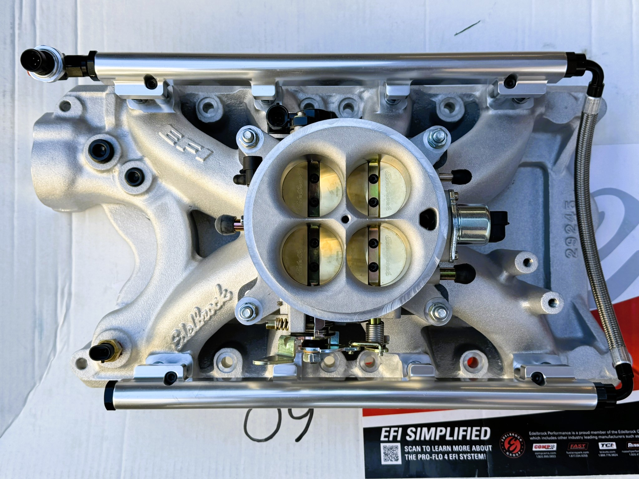
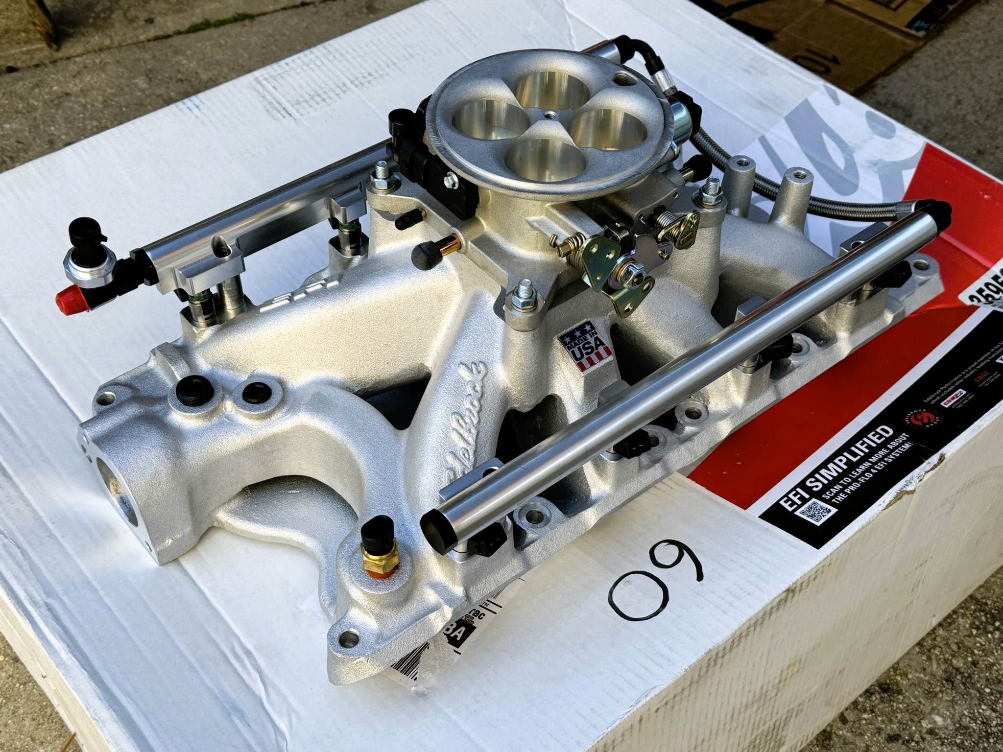
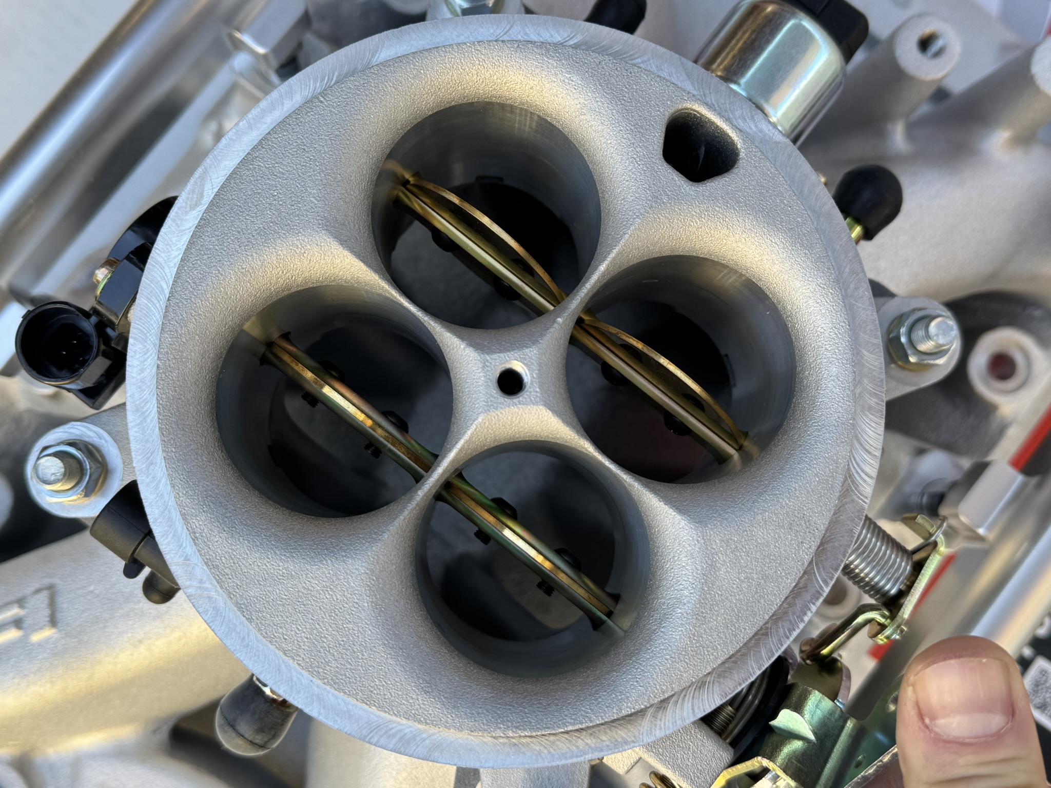
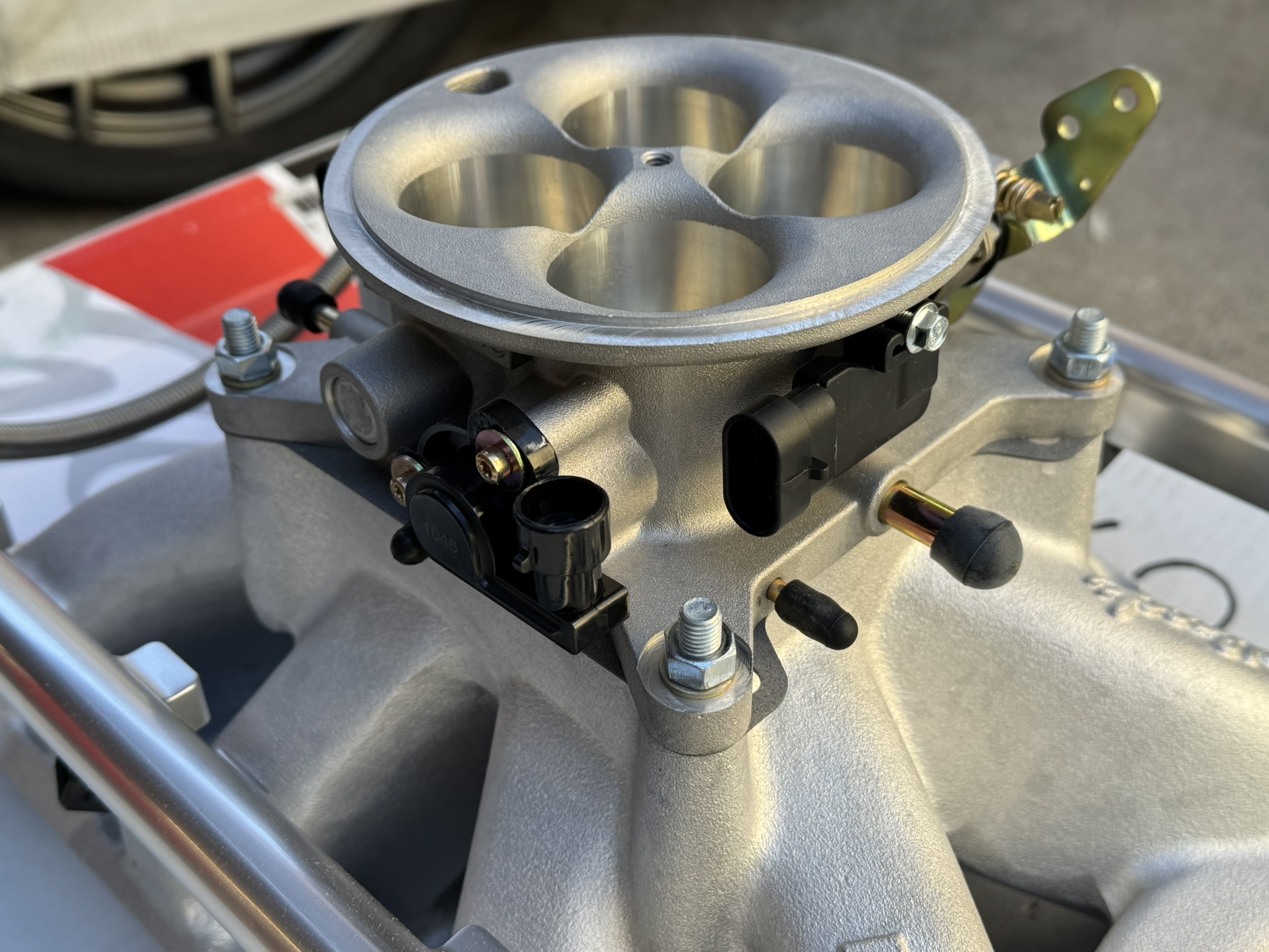
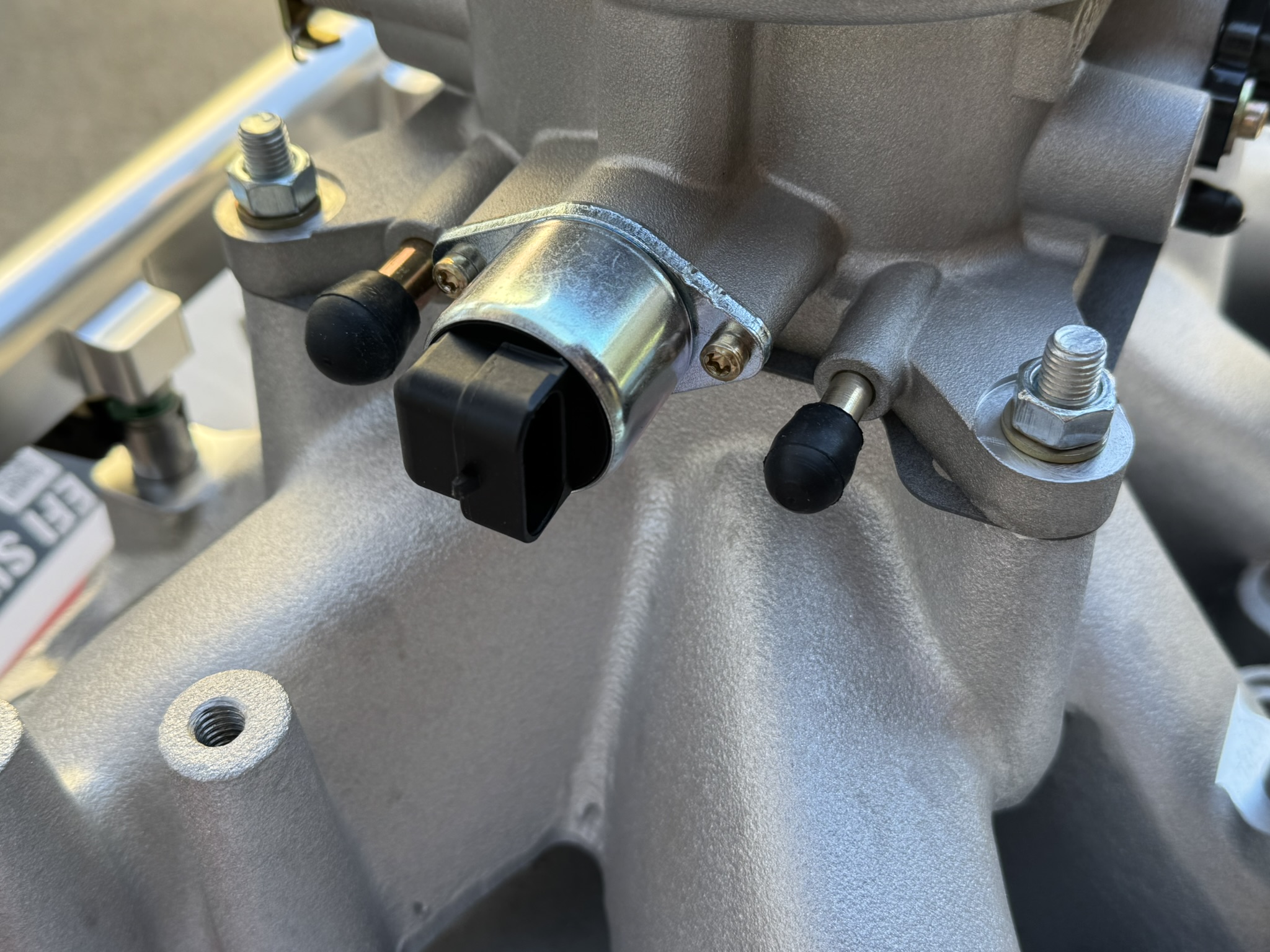
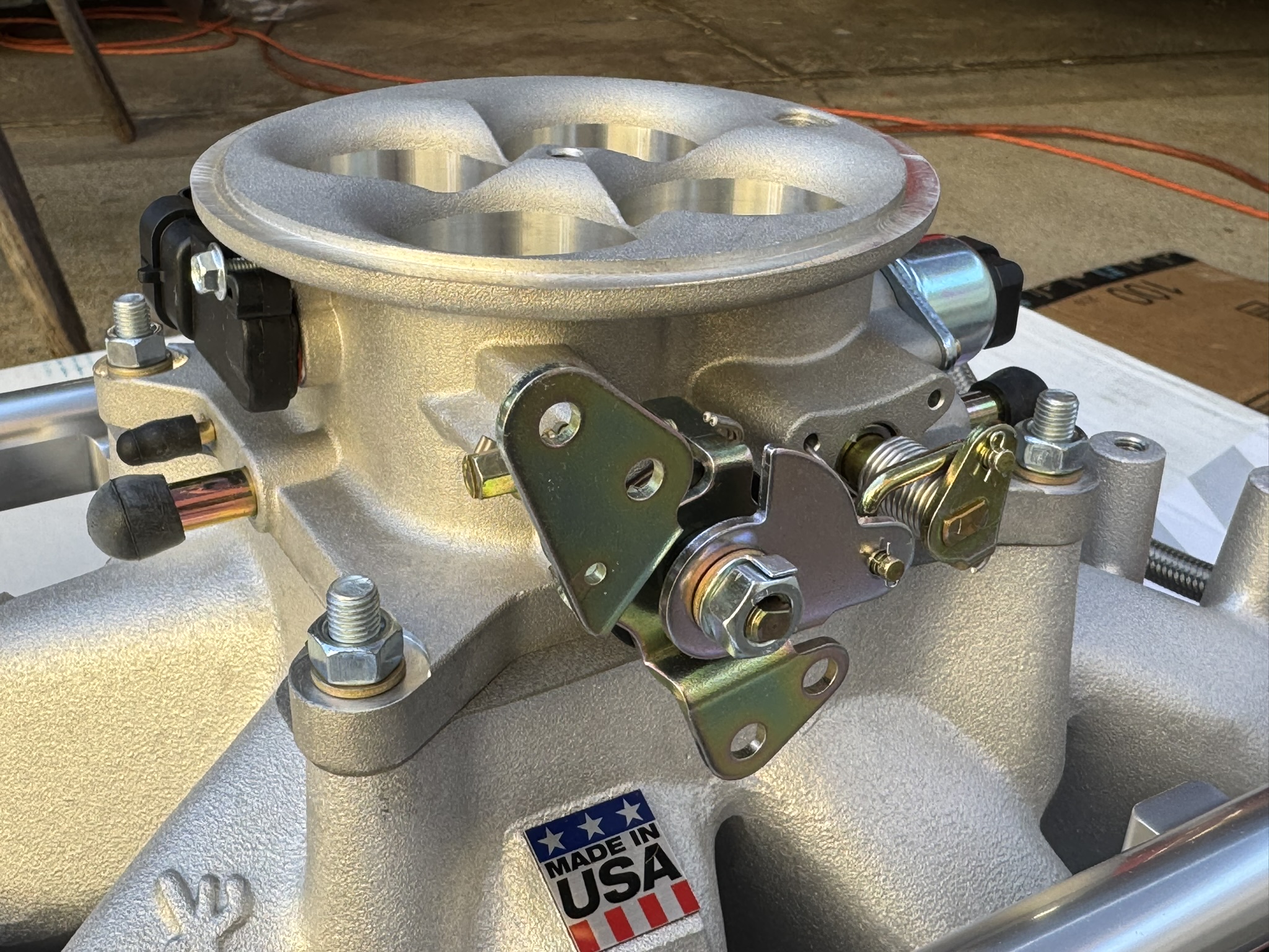
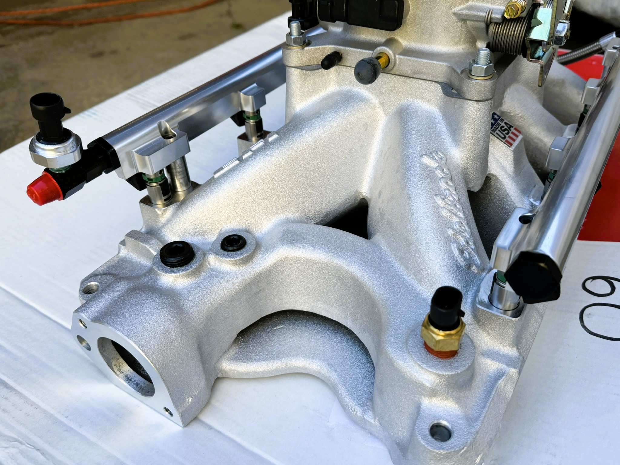
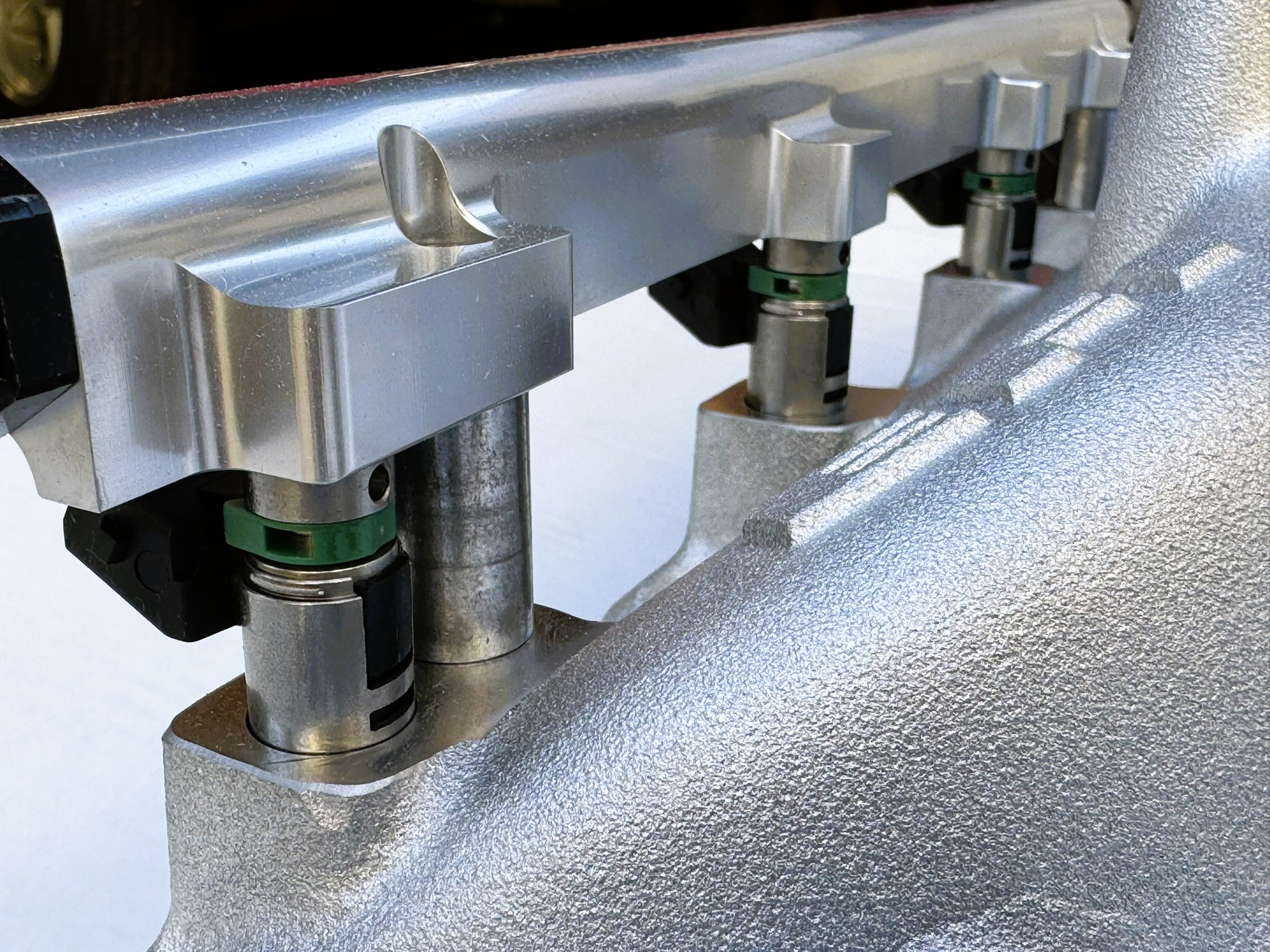
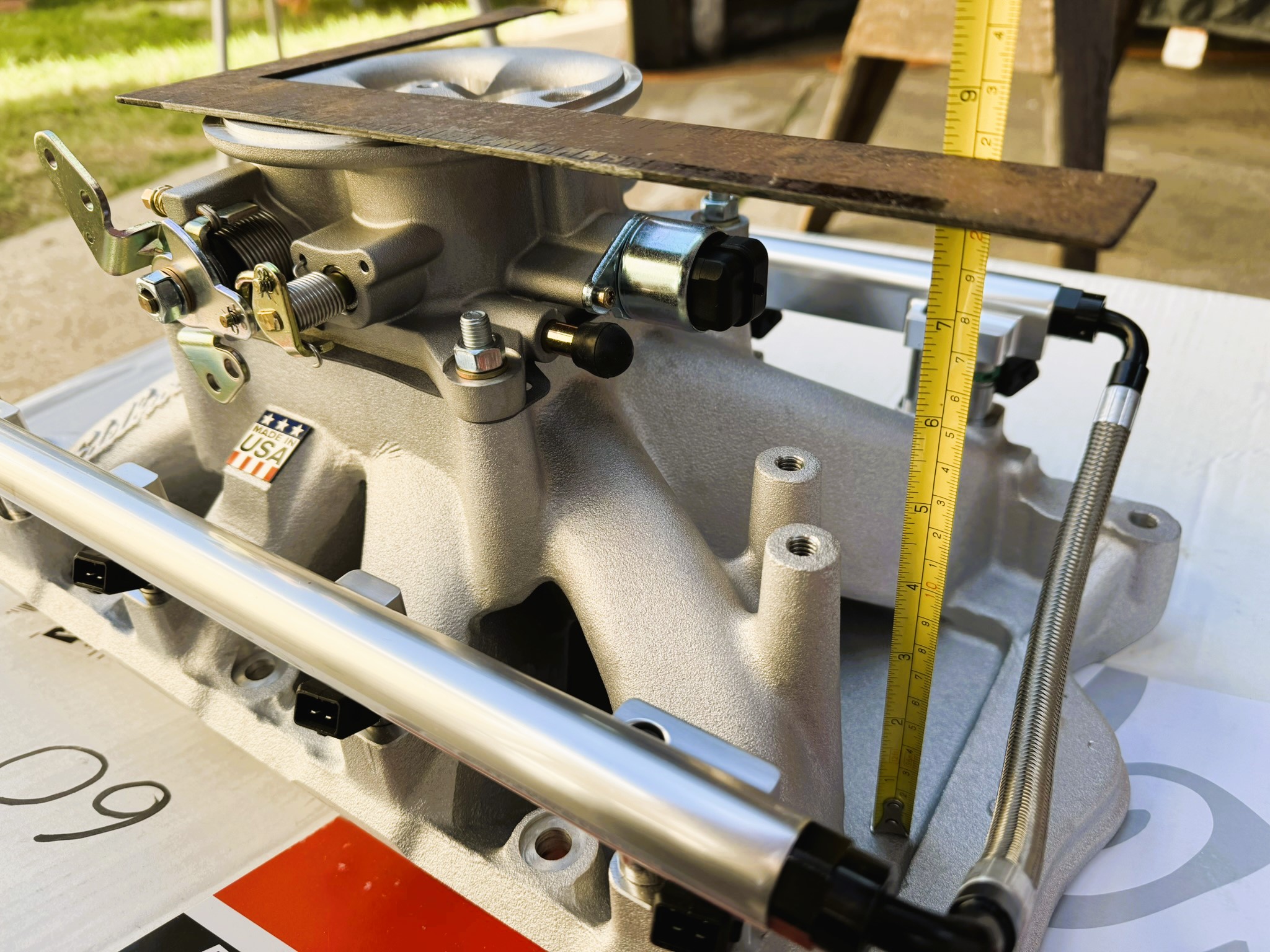
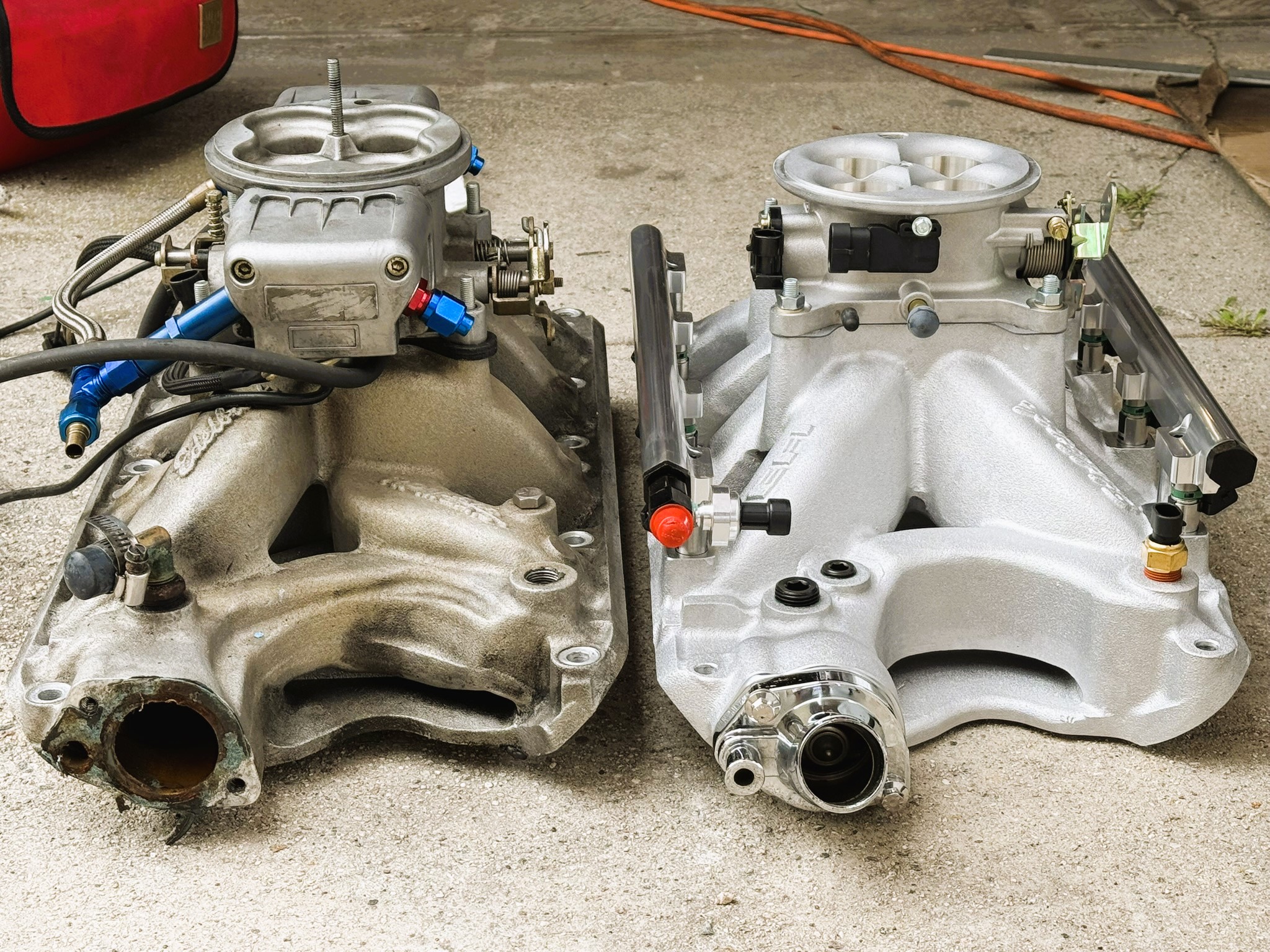
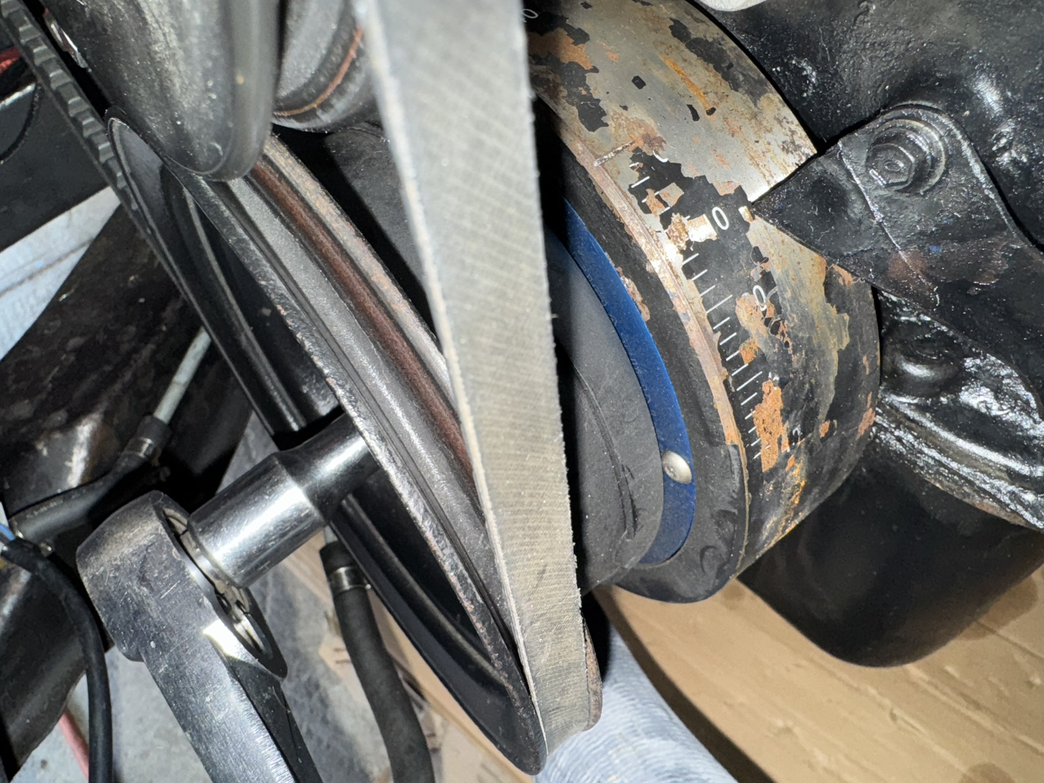
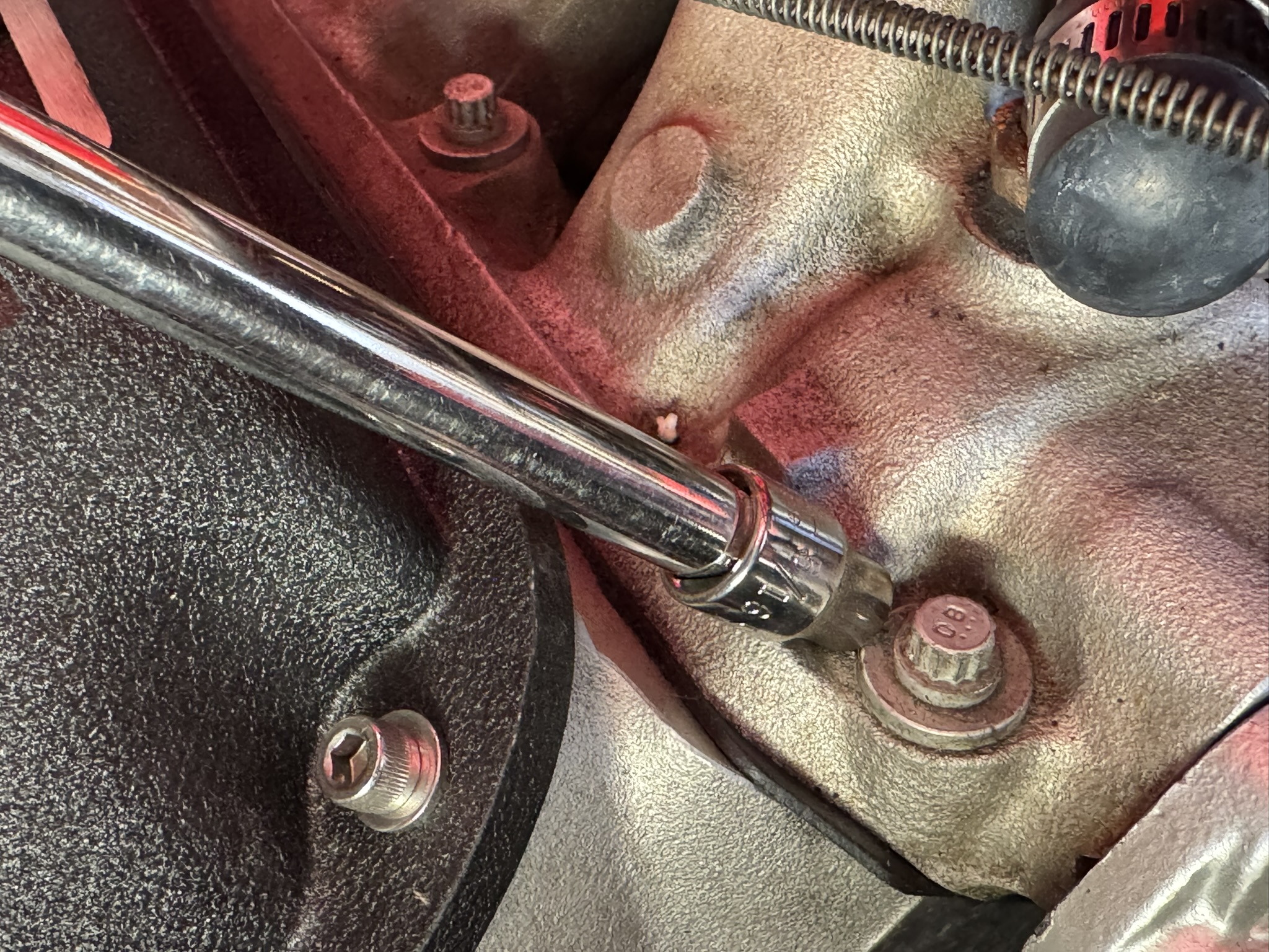
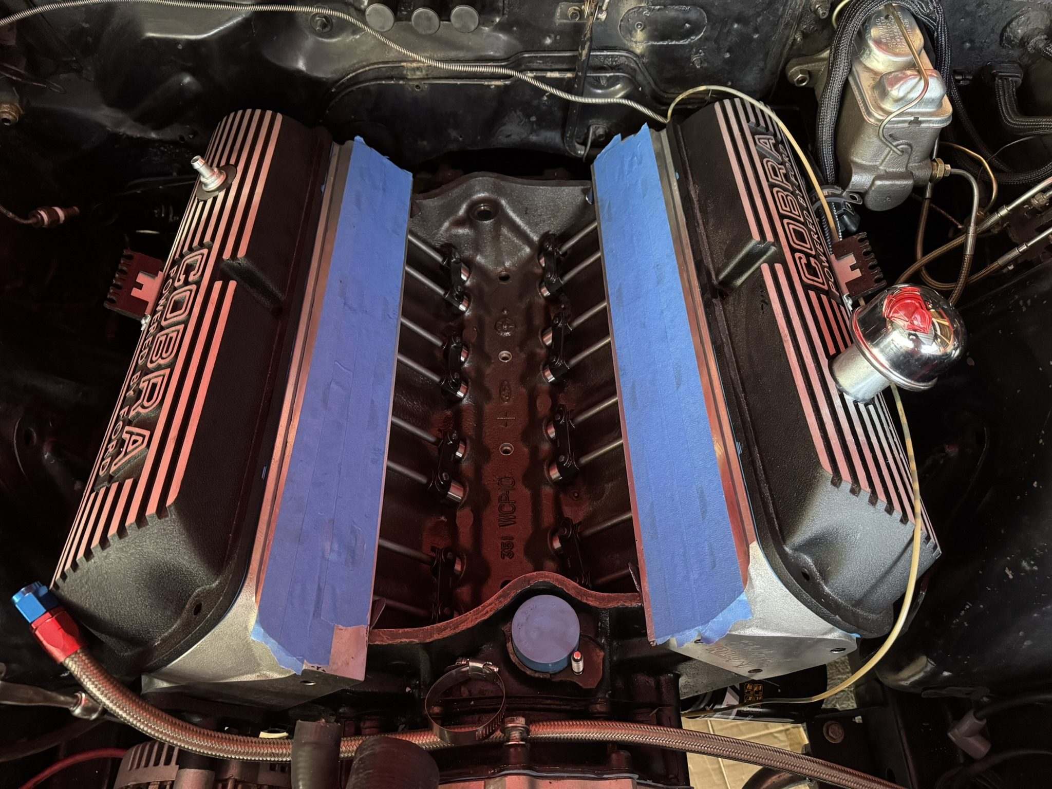
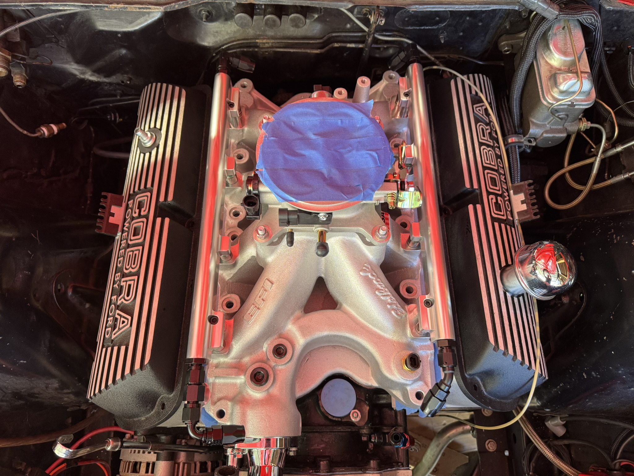
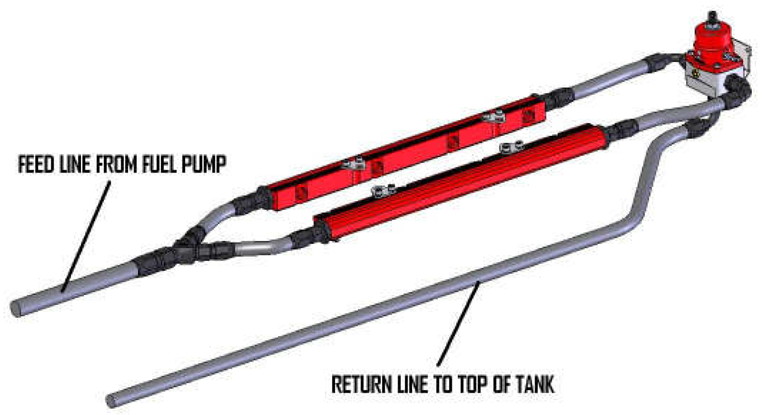
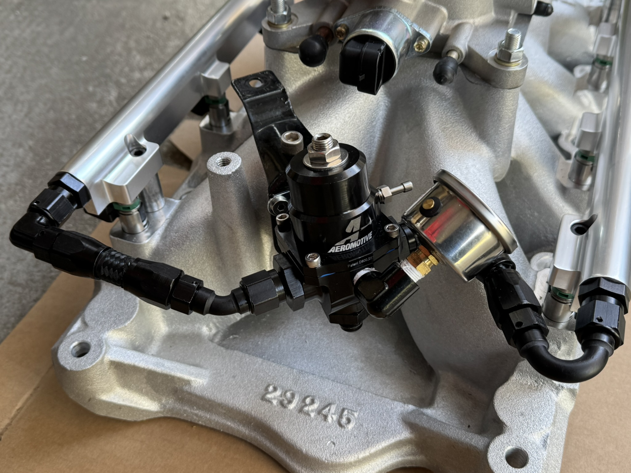
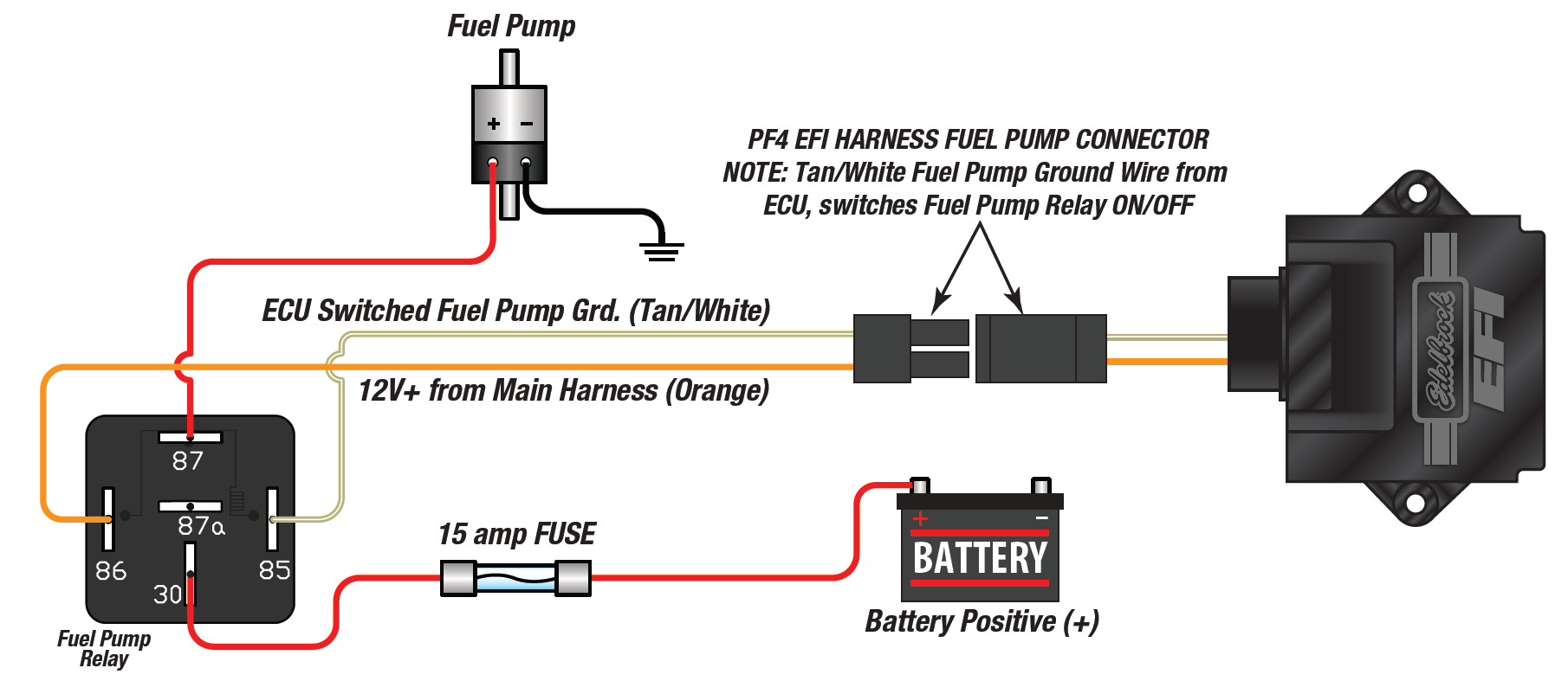
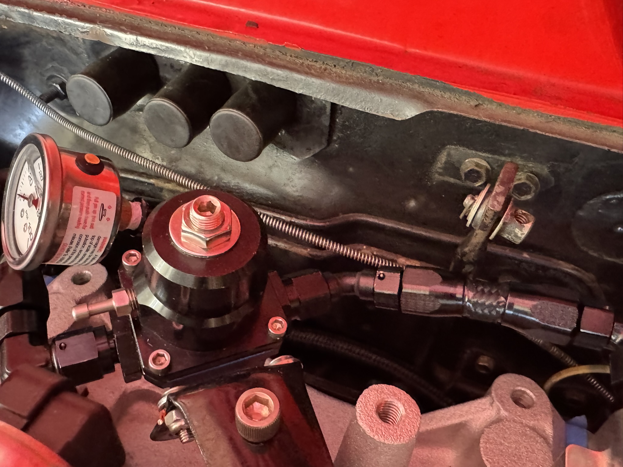
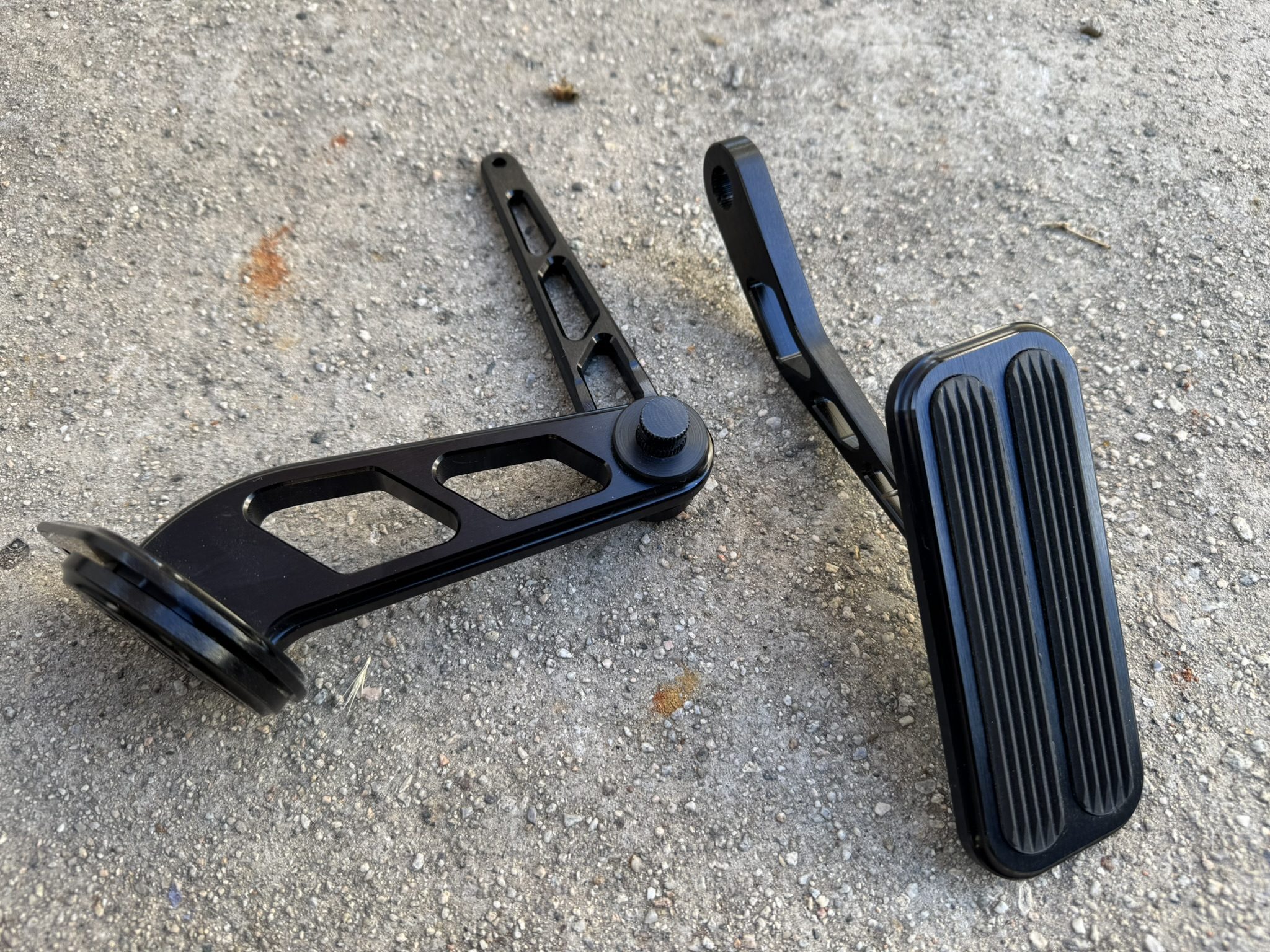
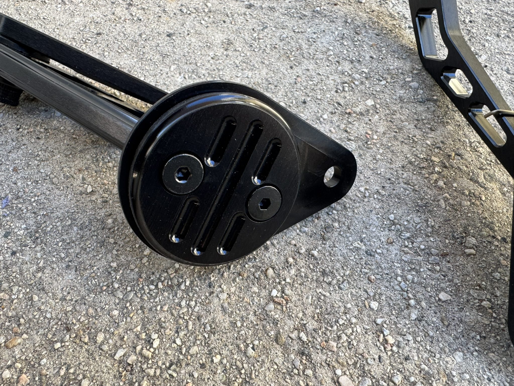
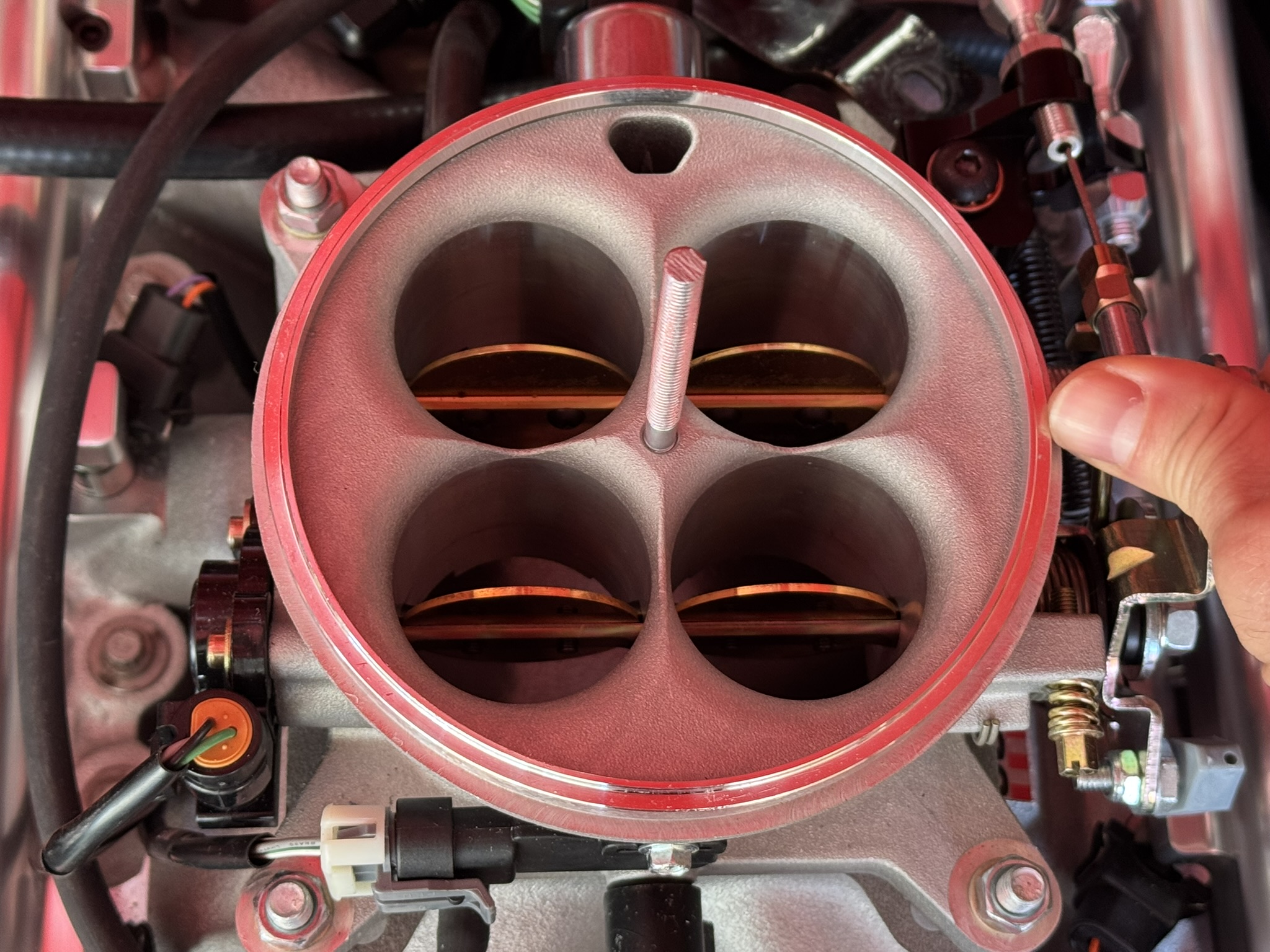
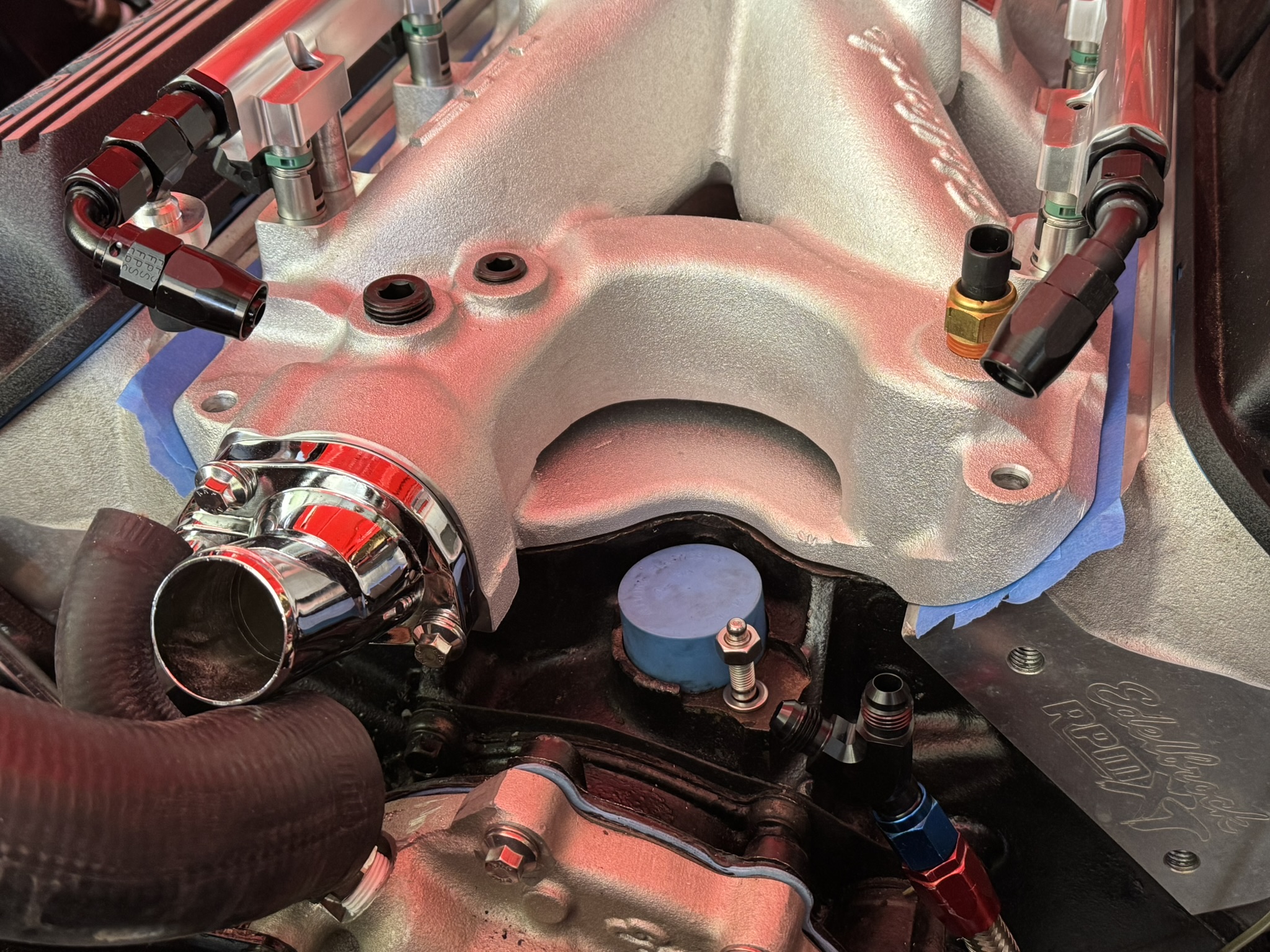
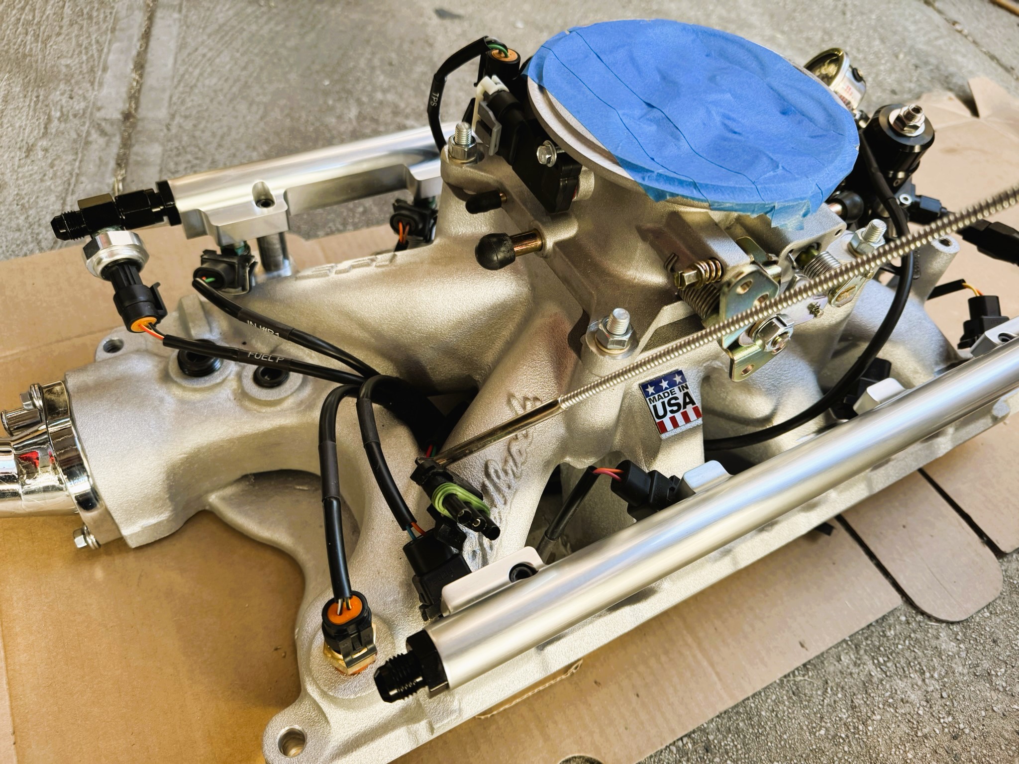
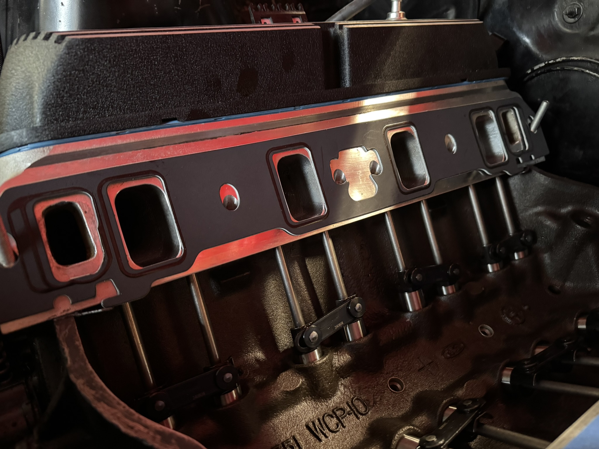
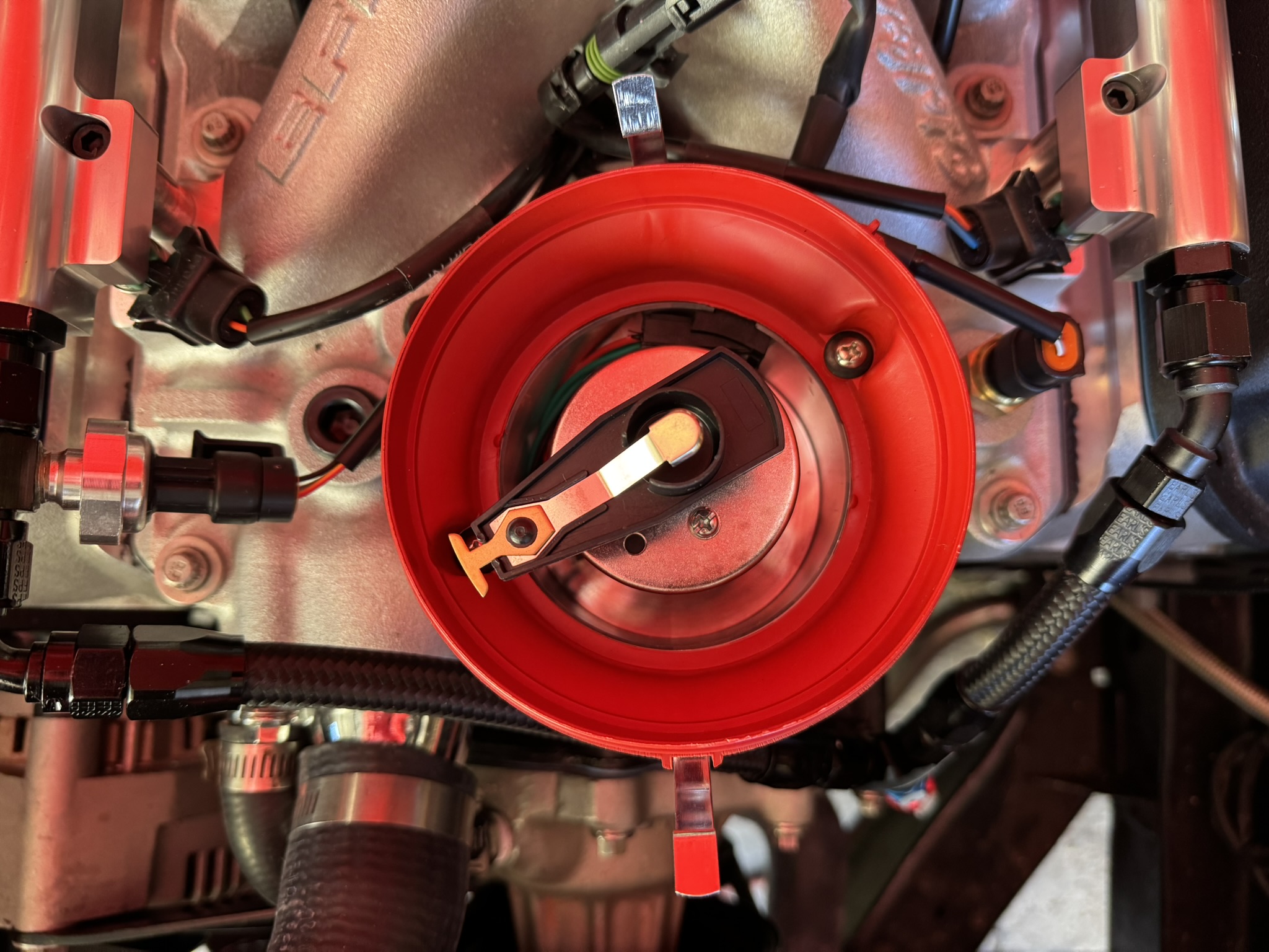
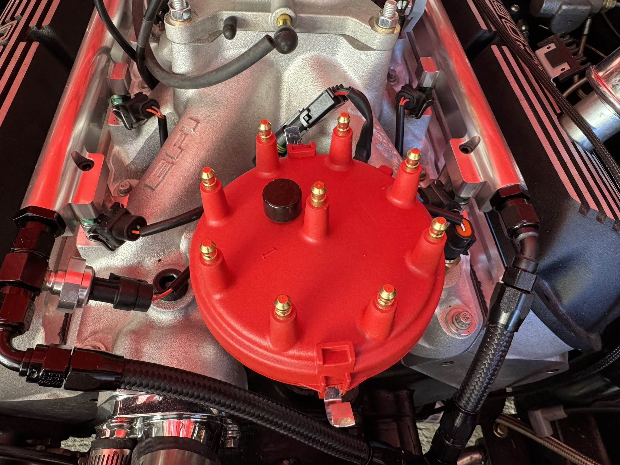
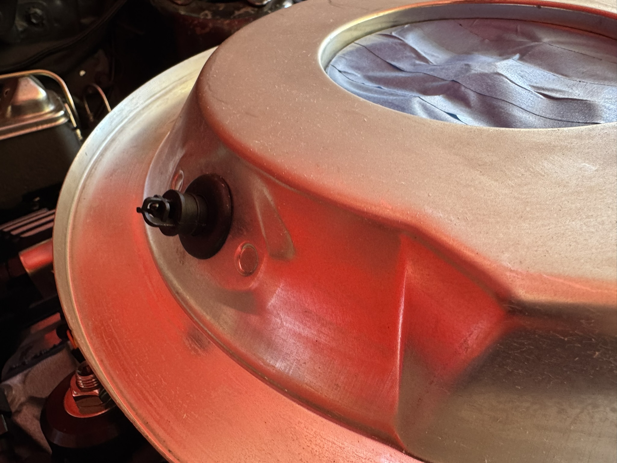
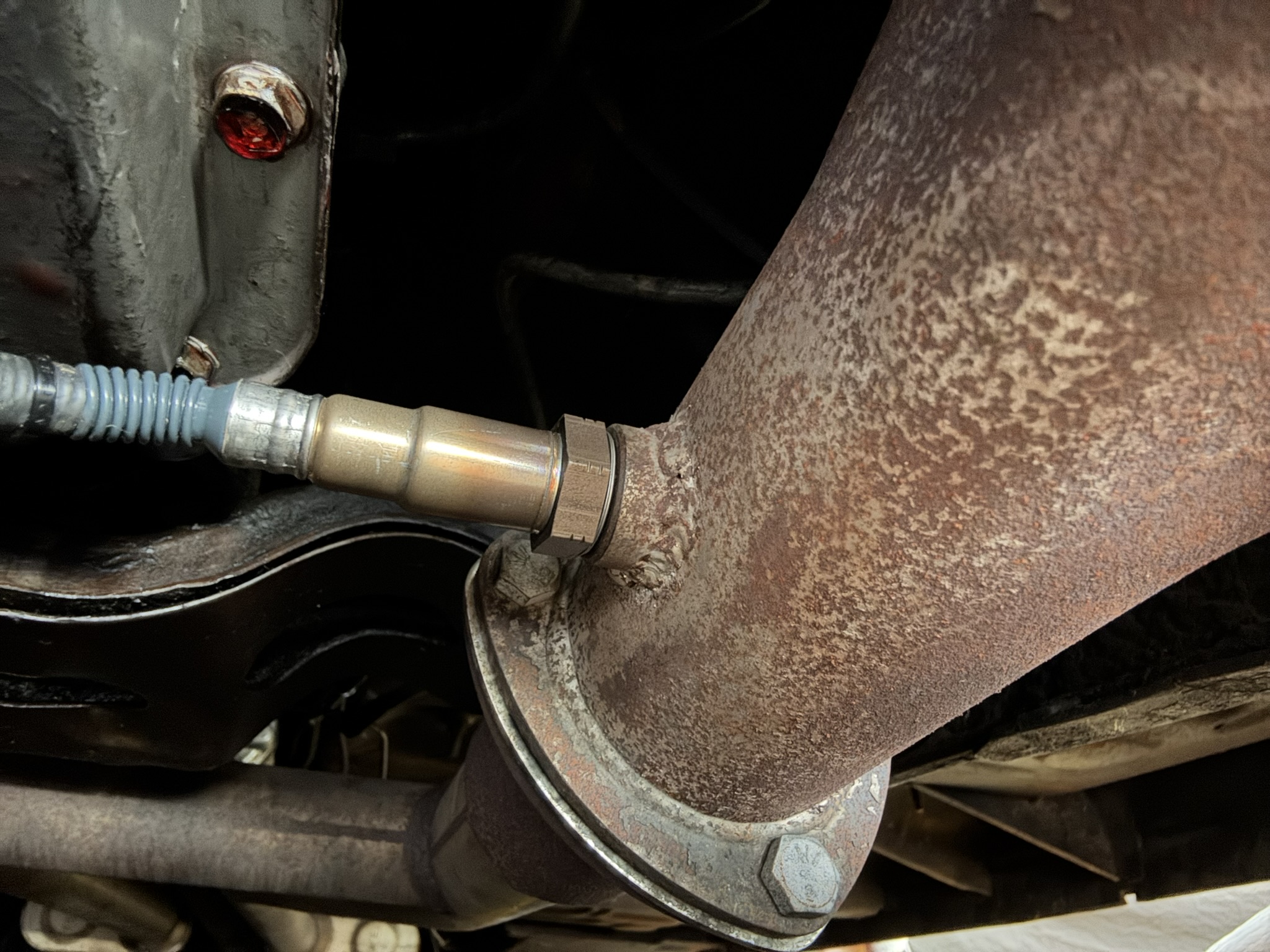
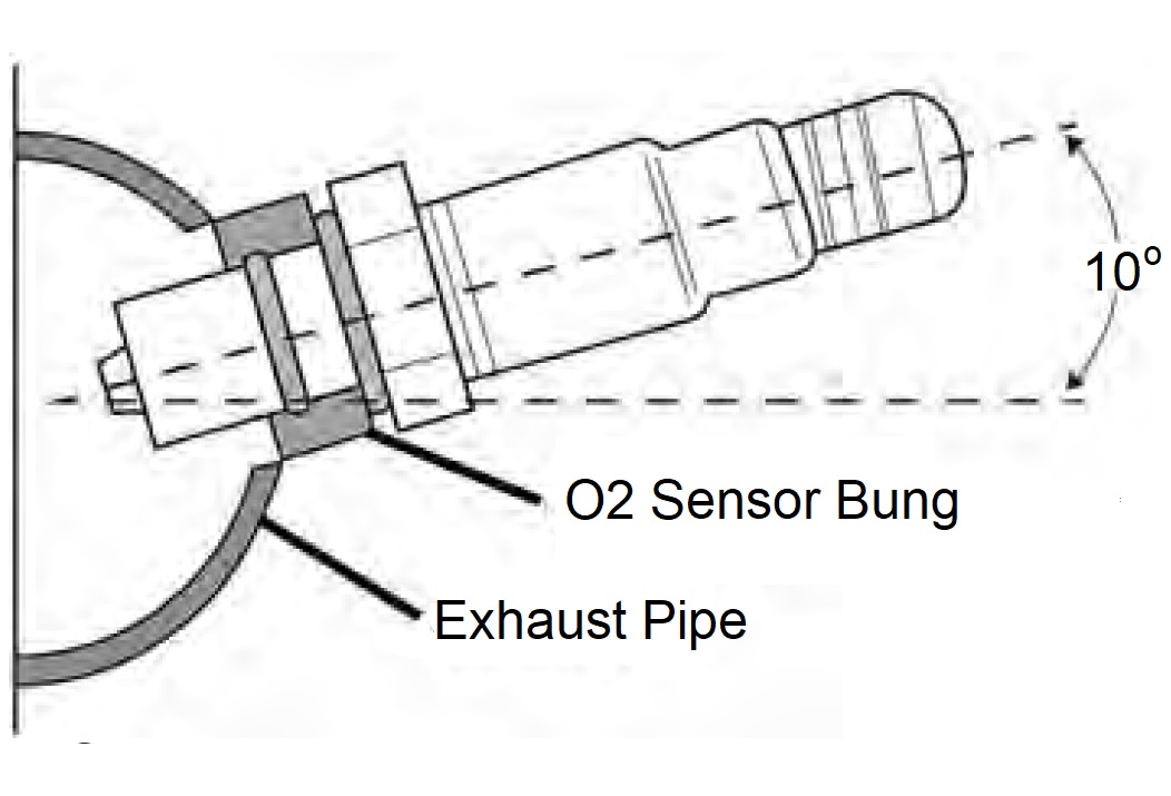
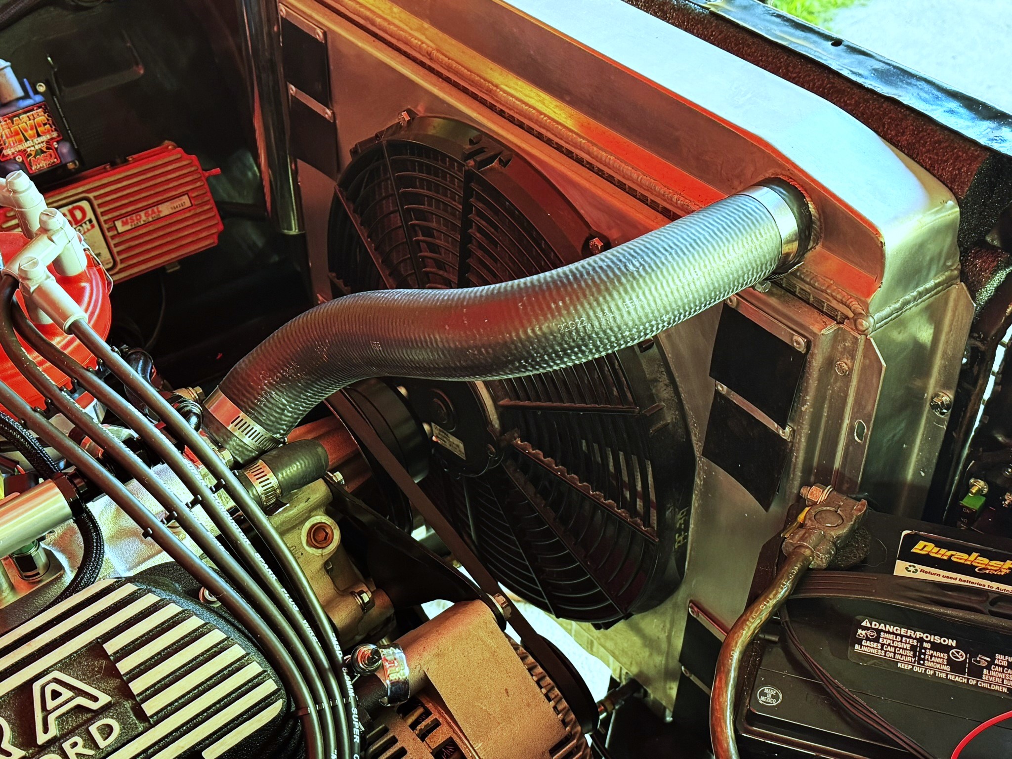
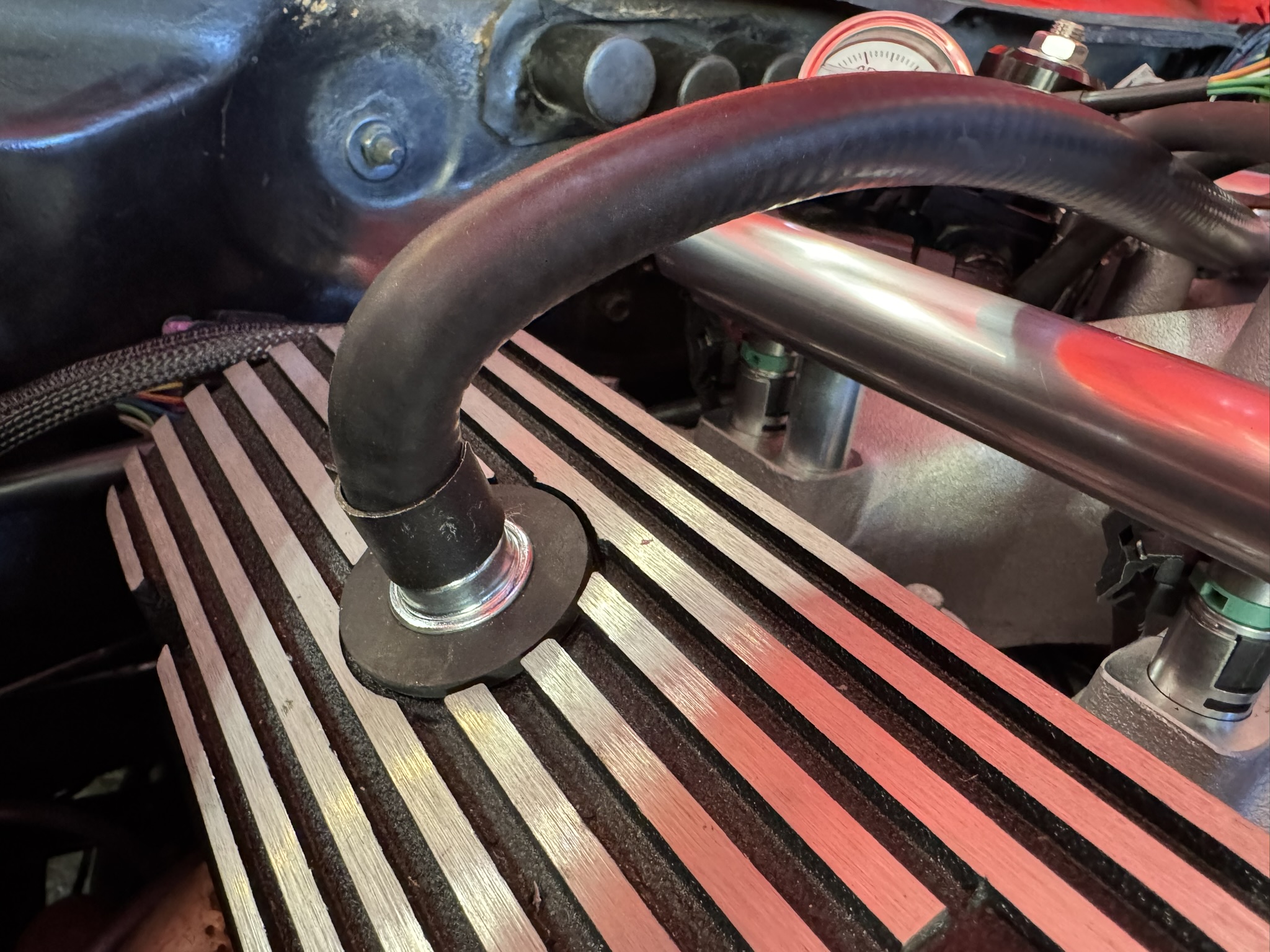
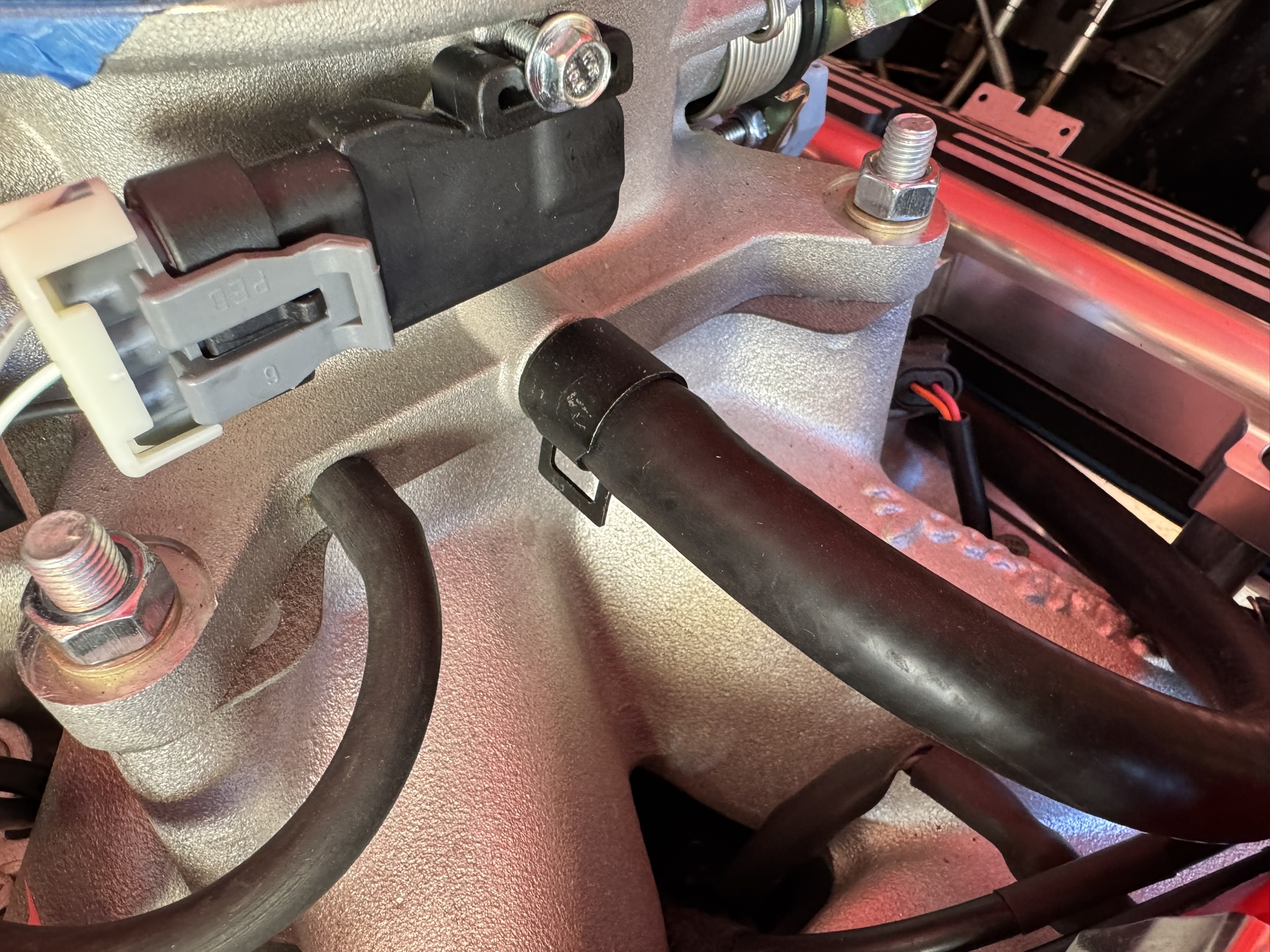
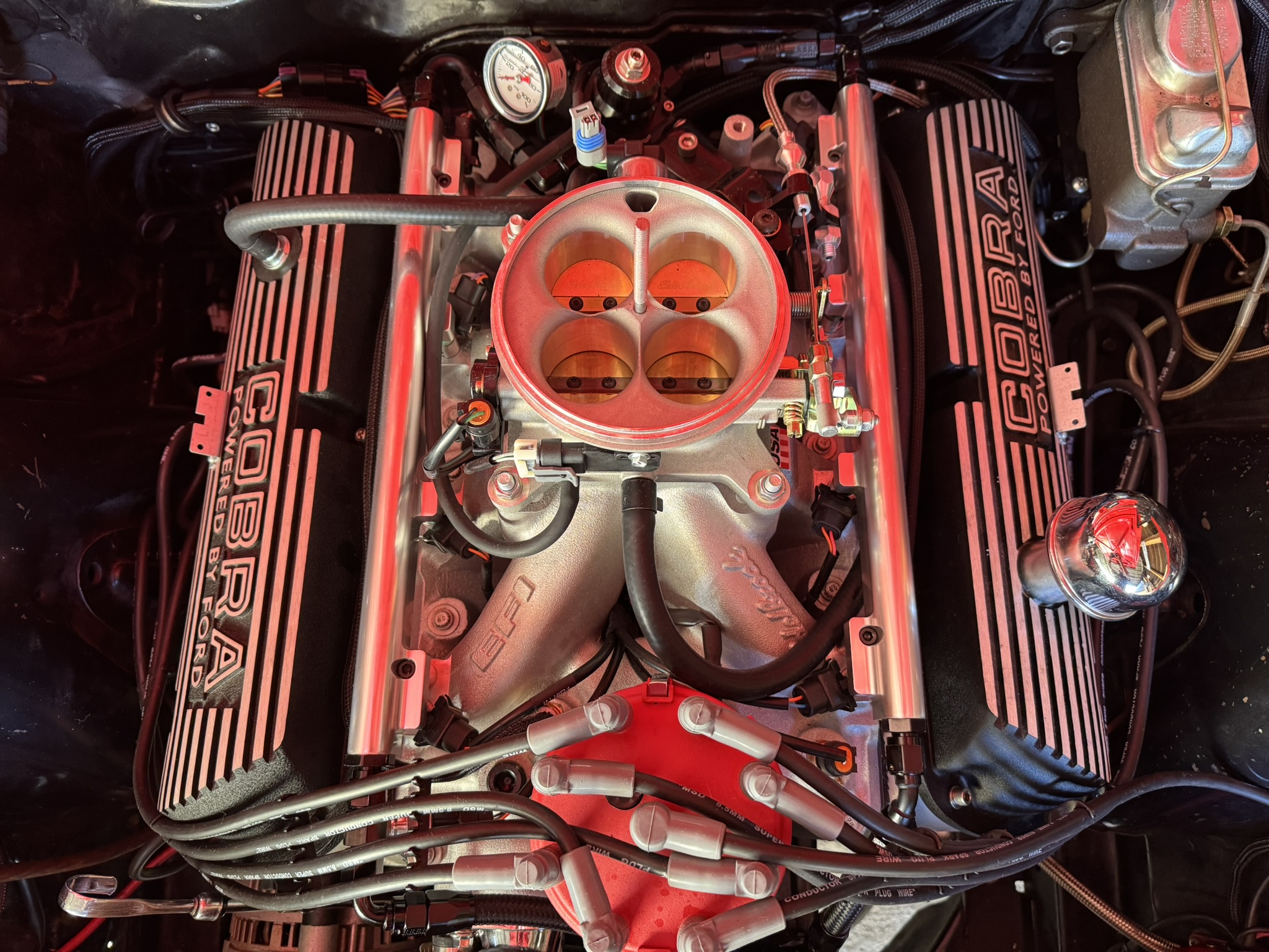
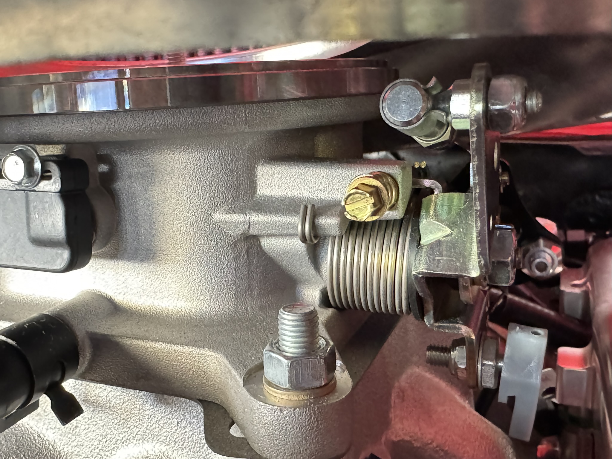
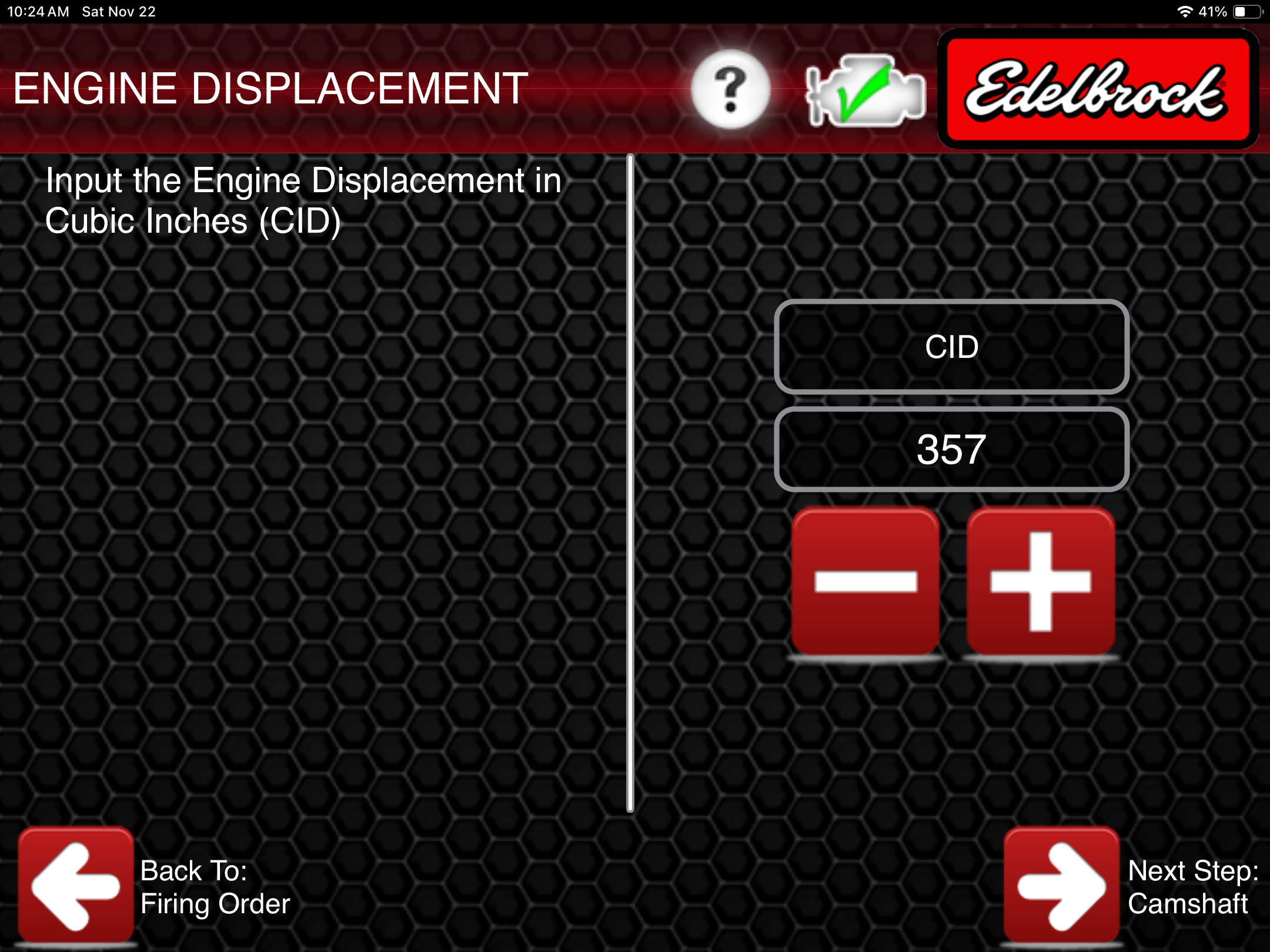
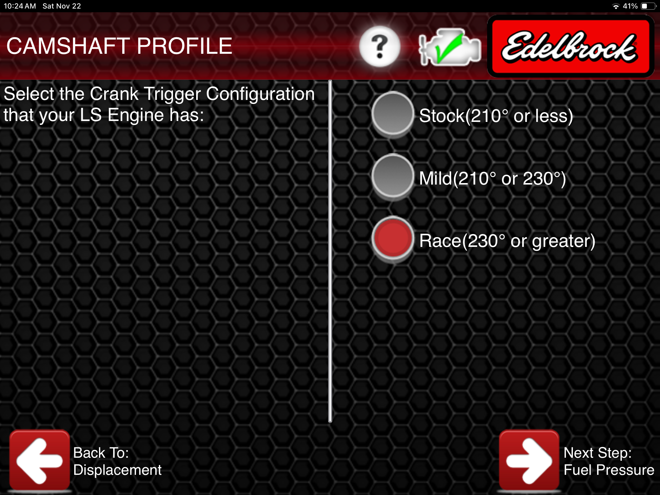
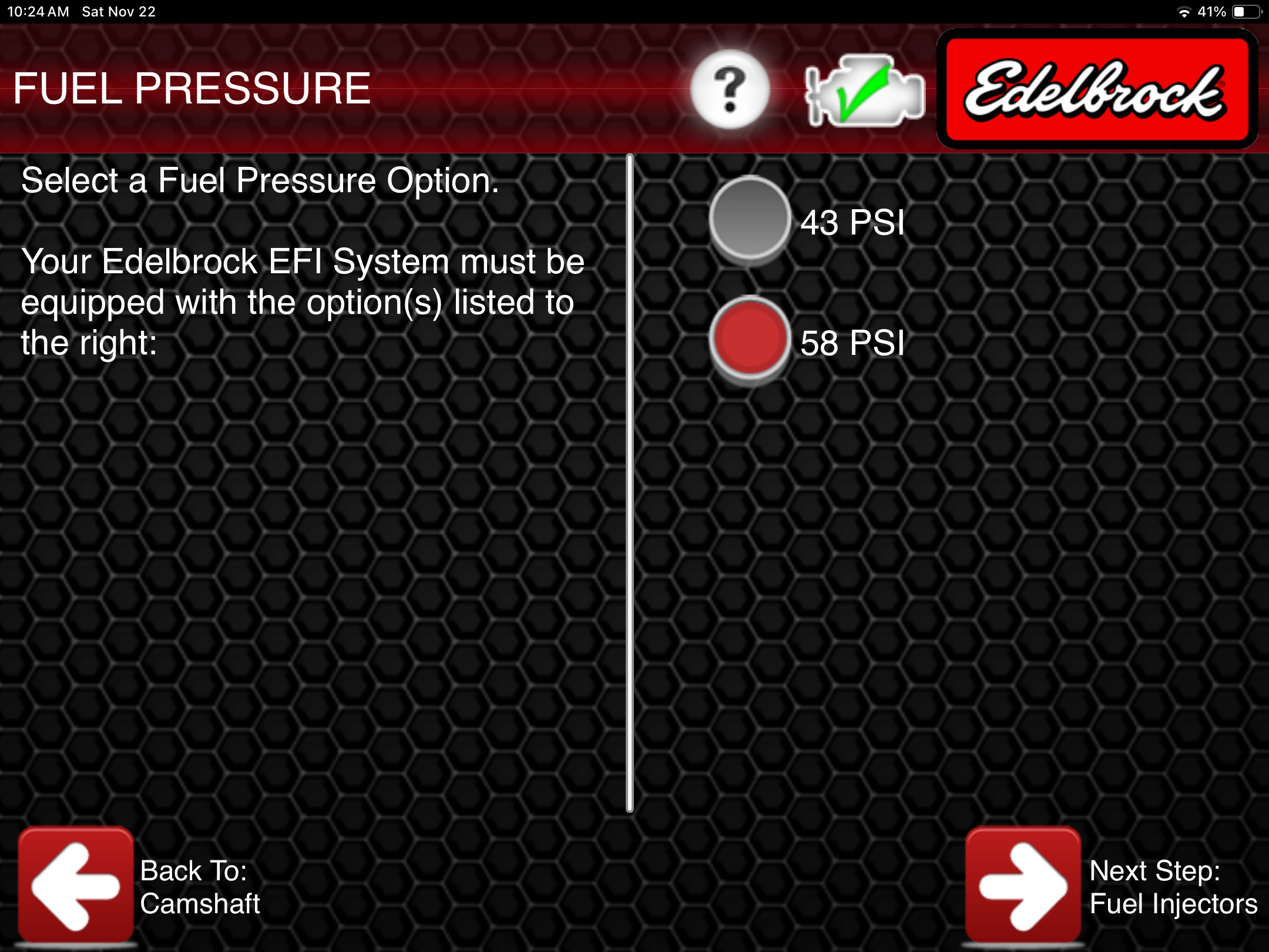
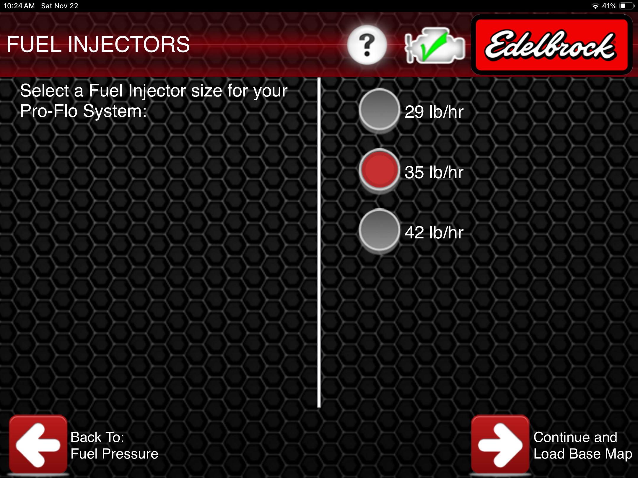
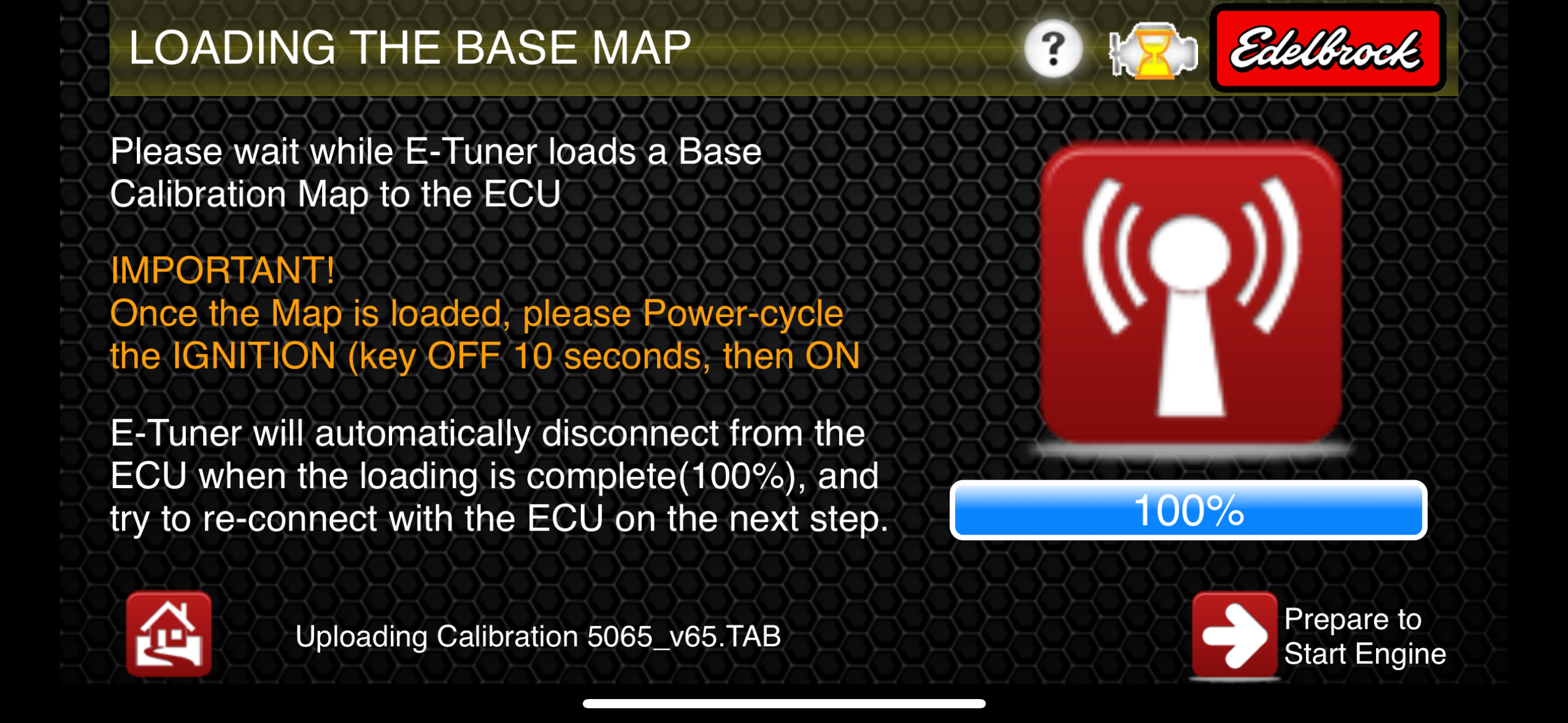
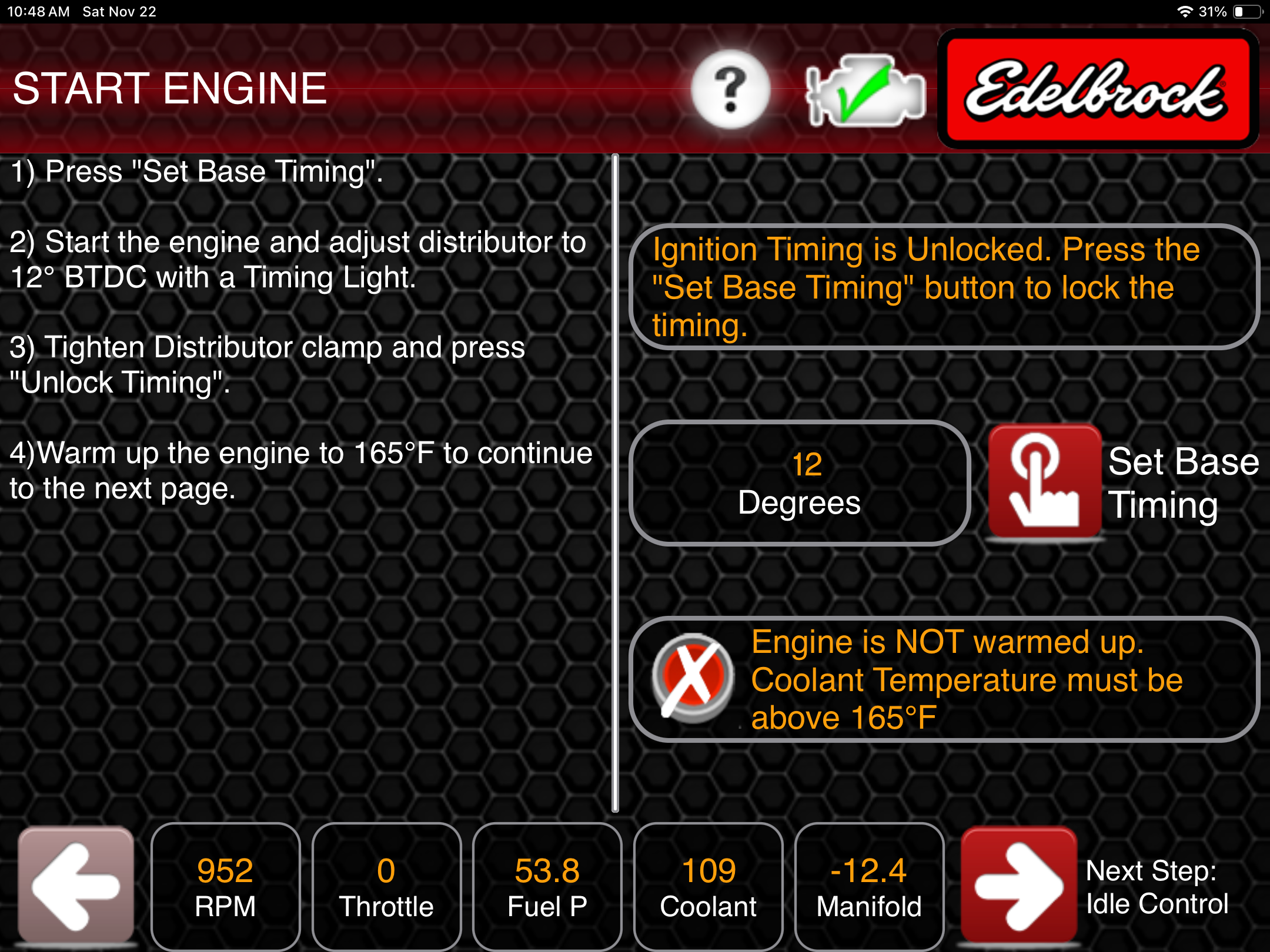
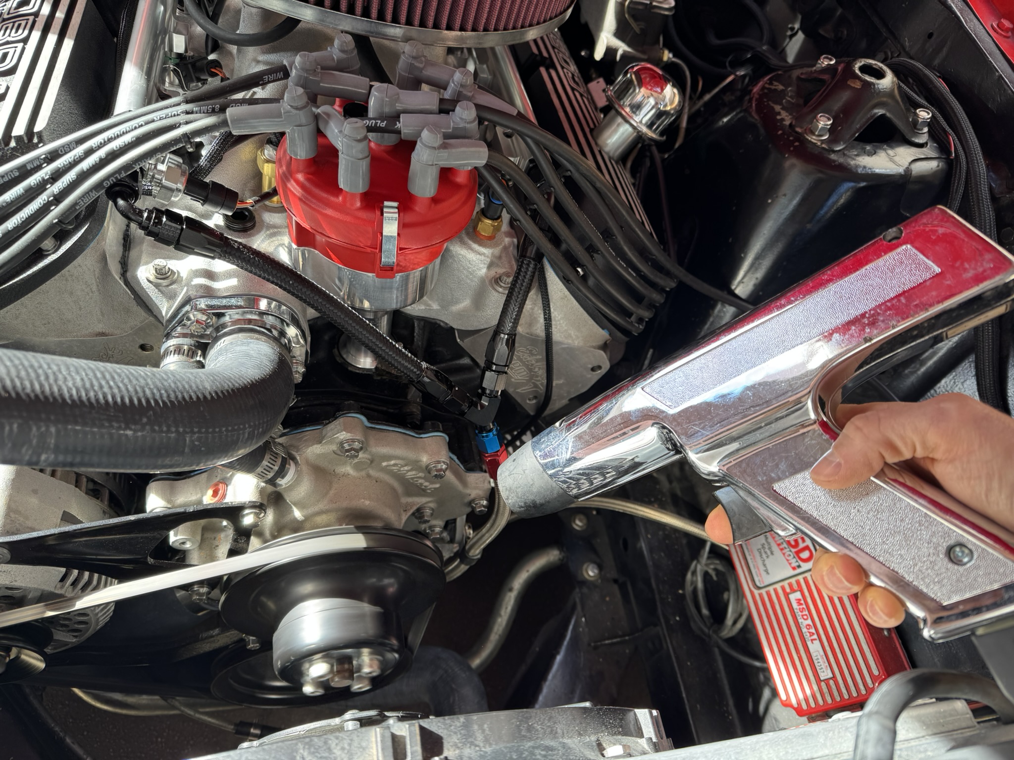
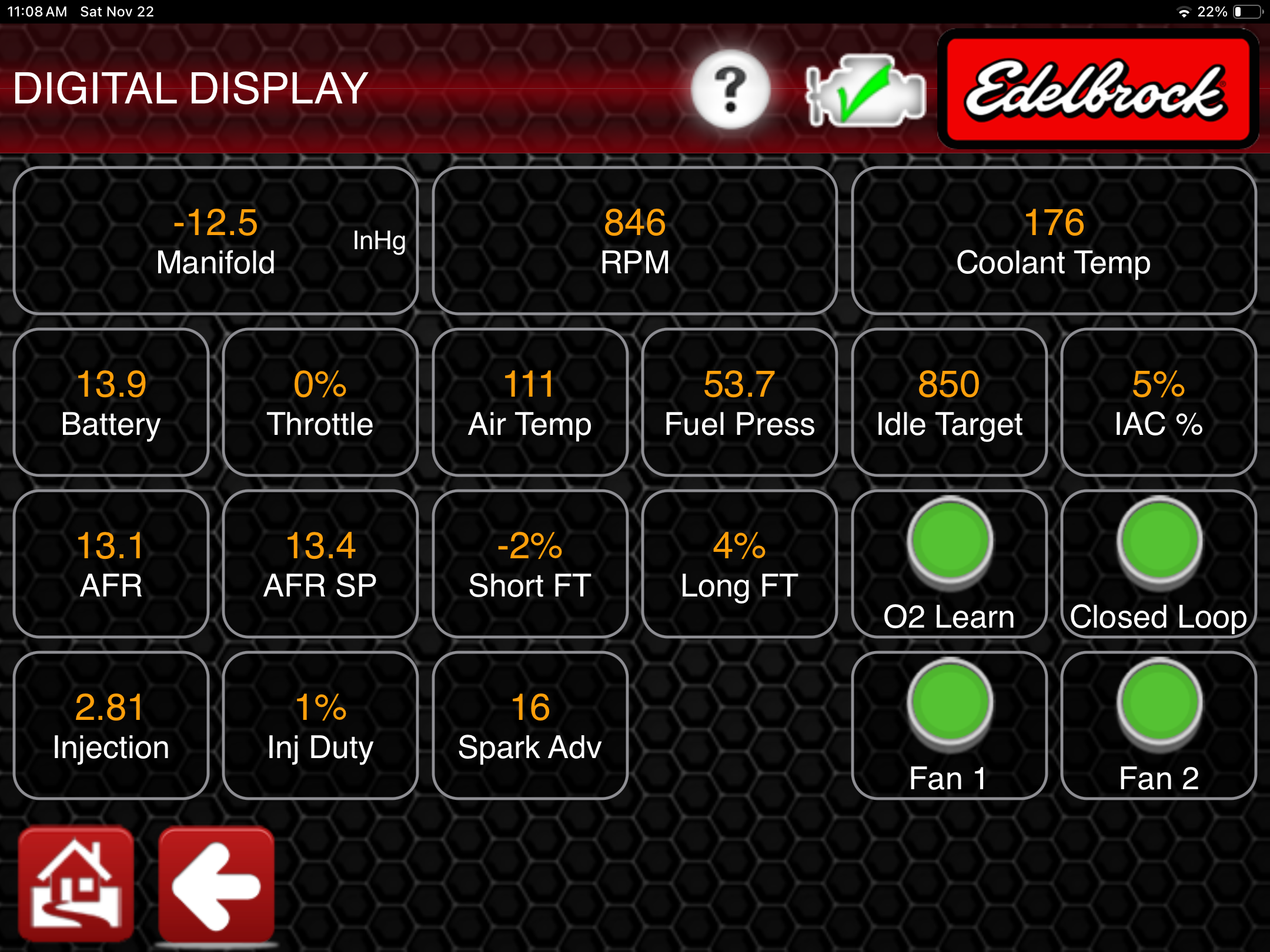
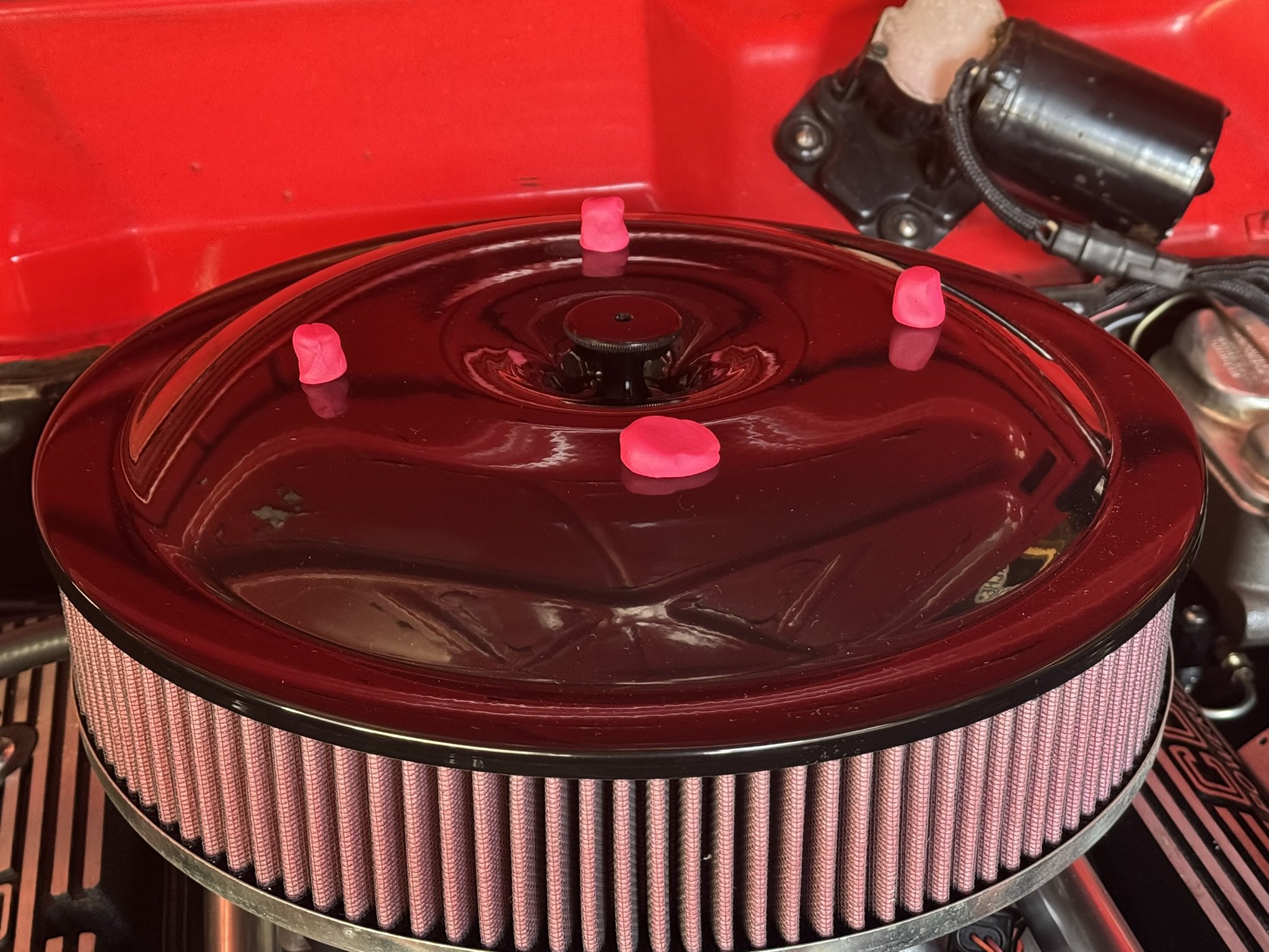
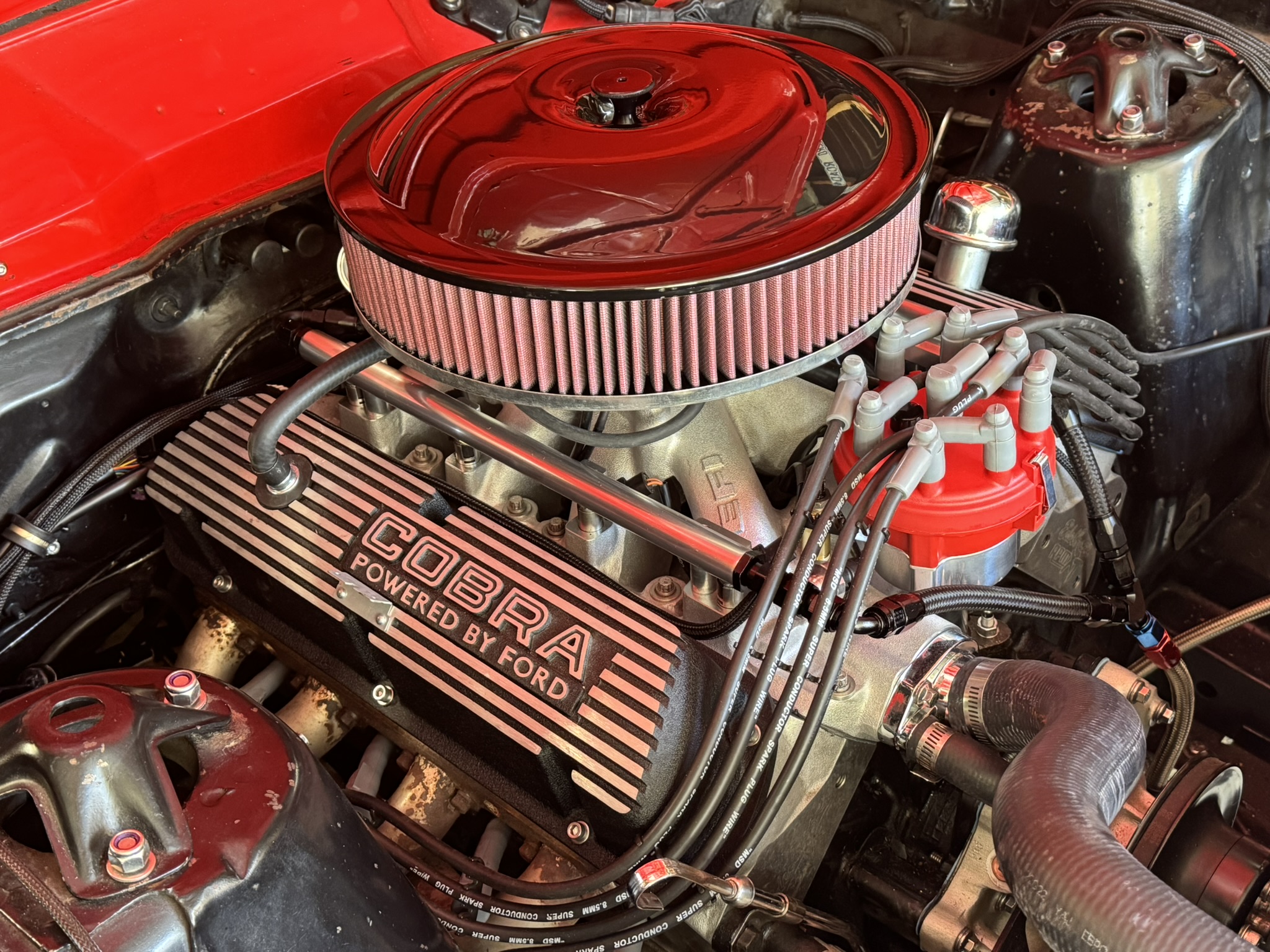
Out of the box and ready to go; the Pro-Flo 4 really is one of the most user-friendly port EFI swap kits for the 351W. (Image/Christopher Campbell)Edelbrock goes the extra mile and ships the Pro-Flo 4 kits with the new intake fully assembled with fuel rails, injectors, low rise throttle body, all sensors installed, and a simplified wiring harness. The system is tested, pressure checked, and flowed at the Edelbrock factory, so everything is ready to go right out of the box. (Image/Christopher Campbell)The Pro-Flo 4 system uses a 4150-style flanged throttle body with four throttle blades arranged in a conventional 4-barrel pattern and flows up to 1,000 CFM. (Image/Christopher Campbell)On the front of the throttle body, you’ll find the MAP sensor and just to the left is the throttle position sensor (TPS). At the base is a 3/8″ port with full time vacuum and port with manifold vacuum. Speaking of MAP sensor, the Pro-Flo is boost compatible up to 15 psi by switching to a 2-bar MAP sensor and downloading a free firmware update from Edelbrock. (Image/Christopher Campbell)On the rear of the throttle body is the idle air control (IAC) motor. At the base to the left is another 3/8″ port with time vacuum port and another manifold vacuum port. Per Edelbrock’s tech line, either full time vacuum port can be used for PCV or power brake booster. (Image/Christopher Campbell)The linkage is not a traditional carb style, so you’ll need to think through and test your stock throttle linkage and air cleaner for fit and function. We had issues with both, but more on that later. (Image/Christopher Campbell)On the front right corner of the intake, Edelbrock was nice enough to preinstall and seal the water temperature sensor. On the left we’ve got two additional ports for the heater hose fitting and an additional sensor. (Image/Christopher Campbell)Under those beautiful billet rails, the Pro-Flo 4 uses small body “shorty” style fuel injectors to offer extra clearance for various air cleaner assemblies. The green band tells us that these are 35 lb./hr. injectors, which are good for around 550 hp naturally aspirated at 58 psi. (Image/Christopher Campbell)How tall is the whole package with the Victor Jr. intake? Shockingly short thanks to the low-profile throttle body. The overall height from the rear of the intake to the throttle body is 8-3/4 inches. (Image/Christopher Campbell)Here’s the answer to another common question we saw on the forums. The Pro-Flo 4 kit with the Victor Jr. intake and Edelbrock throttle body is a full inch shorter than an Edelbrock RPM Air-Gap intake with a standard Holley style carb (or Holley carb style throttle body in our case). That’s great news for hood clearance! (Image/Christopher Campbell)The Pro-Flo 4 comes with its own bespoke electronic distributor, but before you pull your current distributor, make sure to rotate your engine to 12 degrees BTC on the intake stroke. If your harmonic balancer looks a bit hard to read like ours, we recommend a metal marker to make sure you can see the 12-degree mark when you crank the engine. (Image/Christopher Campbell)The Pro-Flo 4 kit doesn’t include bolts, so we recommend picking up an Edelbrock intake manifold bolt kit if you don’t already have one. We’ll be reusing ours. (Image/Christopher Campbell) We won’t bore you with the intake manifold removal process, just make sure your intake sealing surfaces on the heads and engine block are clean, and we highly recommend some painters tape over the intake ports while you trial fit the Pro-Flo intake. (Image/Christopher Campbell)With the Pro-Flo manifold dropped onto our 351W, it’s time to start mapping out the routing for our fuel lines and wiring and looking for potential issues. Expect to put it on and pull it off a few times if you’re doing anything custom, working on a non-standard application, or if you’re just very particular about the cleanliness of your install like us. This was our first check, and we already spotted a throttle arm interference. (Image/Christopher Campbell)Since the Pro-Flo 4 kit does not include a fuel system, here’s where our project is going to divert from a standard install. While the Pro-Flo 4 arrives set up for a returnless style fuel system (single fuel line), our project already has an Aeromotive fuel system plumbed with a return line, so this is the basic plumbing diagram we’re following, per Aeromotive’s recommendation. If you want to keep it simple and retain the returnless fuel system, we recommend purchasing the Edelbrock Pro-Flo 4 Fuel Pressure Regulators EDL-17401 (Image/Aeromotive)We removed the braided stainless crossover line from the rear of the fuel rails and pieced together a way to mount our Aeromotive fuel pressure regulator with a few Earl’s AN fittings and a leftover bracket that we had stored away. This arrangement keeps everything nicely tucked behind the throttle body and will allow us to use our current supply and return fuel line routing. You can see full details on our Aeromotive Phantom 340 fuel system in this article.(Image/Christopher Campbell)If you’re planning to run a fuel pump with a very low amp draw (less than 10 Amps) you can drive it directly from the Pro-Flo ECU. For reference, a conventional Walbro 255 LPH type pump or equivalent is typically acceptable. Our Aeromotive Phantom 340 pump pulls ~14 amps, so we will use a relay wired as shown here. When the ignition switch is turned on, the ECU will run the fuel pump for eight seconds to prime the fuel system and then shut off. The fuel pump will turn on anytime an RPM signal is detected by the ECU. (Image/Edelbrock)If you’re installing a Pro-Flo 4 on a pre-1969 FoMoCo vehicle like us, make sure to check clearance with the throttle arm, especially if you’re tempted to copy our FPR location. Our throttle arm already had clearance issues before adding the Aeromotive regulator and plumbing, and this set up made it non-functional. Check your throttle linkage as well, the Pro-Flo 4’s linkage has a motion ratio that will not work with most threaded throttle rods. If you have a factory throttle cable, (like 1969 and later Mustangs) you may be good to go. (Image/Christopher Campbell)If you find yourself in the same situation as us, you have a couple of options. You can swap to a factory cable throttle from a 1969-73 Mustang or use the Lokar conversion pedal. We highly recommend the Lokar pedal due to the high level of adjustability it offers. (Image/Christopher Campbell)These Lokar pedals are designed for 1965-68 Mustang and Cougar, but many FoMoCo vehicles use the same style firewall mount, so they can work for many other projects as well. For example, it works perfectly for the 1966-67 Fairlane. (Image/Christopher Campbell)The Lokar pedal was a “must do” in our case, but we highly recommend it in general. The ability to easily adjust the throttle cable and the height of the pedal itself is extremely helpful. You’ll need an extra set of hands to get the mount attached to the firewall, but after that, it’s a very easy installation. (Image/Christopher Campbell)Remember what we said about the motion ratio of the throttle body linkage being aggressive? There’s a specific Lokar bracket to address this issue. This plus a Lokar pedal and Lokar braided stainless steel throttle and kickdown cables solved all of our clearance issues, and made it easy to set our pedal height and ensure we saw WOT at full pedal travel. Also worth noting, the upper hole our throttle cable is installed in is a progressive ratio, while the lower hole is closer to 1:1. We’re still using the Pro-Flo throttle return spring. (Image/Christopher Campbell)Whatever throttle system you end up with, this is the ideal time to make sure that you’re able to get full wide-open throttle (WOT) with the pedal and throttle cable. You’d be shocked how often performance problems can be traced back to an inability to get WOT. (Image/Christopher Campbell)For our return style fuel system, we’re adding a Y-block to our pre-installed supply line from the fuel pump. A 90 degree and a 45 degree -6 AN Earl’s fittings should get our hose routing perfectly aligned. (Image/Christopher Campbell)The Pro-Flo wiring harness is clearly labeled and divided into two major sections. This section includes most of the terminals required on the intake manifold, including the injectors. We highly recommend installing it on a bench (or the ground) rather than on the car if you want to optimally tuck and route the wires. (Image/Christopher Campbell)We give major kudos to Edelbrock on the harness lengths; it was obviously thought out and tested. If you are patient and have a basic wire puller, you can tuck everything nicely through the gap under the intake runners for a very clean and professional look. The thick wraps will keep the wires safe from the heat. (Image/Christopher Campbell)The second major section of the harness includes the connection to the ECU. Here’s where you get to consider if you’re ready to take a hole saw to your firewall or if you want to keep everything under the hood. (Image/Christopher Campbell)We already had a 1.75 inch hole in our firewall from the previous EFI kit, so we opted to mount the ECU under the dash. Unless you are ready to de-pin the harness connector, this is the smallest hole you will be able to get the harness through. Also make sure you figure out what grommet you are going to use before you cut. Ours is a 1967-68 Mustang floorpan plug with the center cut out. No, the harness plugs don’t fit through; we snipped the grommet and super glued it back together afterwards. (Image/Christopher Campbell)The new Pro-Flo 4 ECU is fully potted, so it could be mounted under the hood, but inside the cabin is always preferable and allows for better wire tucking and routing. The ECU is also very lightweight, so we mounted it to our A/C box via heavy duty Velcro. If you’re running electric fans, you will need to run the trigger wire(s) from the ECU into the engine bay with the main harness. The 12v square wave tach pick up is also here at the ECU, if you’re not running a CDI box. (Image/Christopher Campbell)Routing the harness will be very specific to your application, but we highly recommend having some Adel clamps on hand to help keep it tucked up and away from heat. (Image/Christopher Campbell)Now that we’re satisfied with the trial fitting of the fuel system and wiring harness, it’s time for the gaskets. Edelbrock recommends two thin layers of Gasgacinch on the cylinder head side and a thin layer of gasket maker around the intake ports and water jackets on the intake side. Run a 1/4 inch thick bead of gasket maker on the front and rear sealing walls of the block. Torque all manifold bolts in a crisscross pattern starting with the inner bolts and working outwards. (Image/Christopher Campbell)After verifying that the harmonic balancer is still sitting on 12 degrees BTDC, its time for the distributor. Install the O-ring onto the distributor housing and apply a liberal amount of oil or assembly lube to the distributor gear. Install the distributor so that the rotor trigger tooth should be just entering the distributor sensor. (Image/Christopher Campbell)Use the #1 embossed on the distributor cap to verify that you’re in roughly the correct position. Close is fine for now; we’ll dial it when we crank the engine. If you would like to tuck the distributor sub-harness under the intake like ours, this is roughly the distributor alignment that is required. If your previous distributor used this style of terminal, you can put them back on now. If they used the older socket style cap, this is a great time to upgrade to a new set of MSD Super Conductor wires. (Image/Christopher Campbell)Pro-Flo 4 cannot directly fire low resistance, low inductance coils that are intended for use with a capacitive discharge ignition (CDI) box like our MSD Blaster HVC coil. As a rule of thumb, acceptable coils for direct drive are round canister type. Unacceptable CDI coils are typically square or dome shaped. If you want to use a CDI type coil, a CDI box must also be used. (Image/Christopher Campbell)If you already have a CDI box, it can be easily integrated into the Pro-Flo 4 by clipping the terminals off the orange and white coil wires and connecting them directly to the red and white input wires of the CDI box. (Image/Christopher Campbell)Edelbrock provides a very clear diagram to show the proper wiring if you’re starting from scratch with a new CDI box. If you were already running a CDI box, you only need to switch the input wires. Also, if you’re running an aftermarket tachometer, run the trigger wire to the CDI box rather than the tach wire on Pro-Flo 4 ECU. (Image/Edelbrock)The Pro-Flo 4 system uses an intake air temperature (IAT) that needs to be mounted in the air cleaner housing within the air stream. We’re using a K&N 14 inch drop base that happens to have a boss ideal for a hole. The grommet should be snug in the hole, and the sensor should be snug in the grommet. (Image/Christopher Campbell)Another relic from our old EFI system that saved some work is the oxygen sensor bung. If you don’t have a bung already, and aren’t equipped to weld one in, Edelbrock provides a plug for the bung so you can drive to an exhaust shop and get it welded in and not have to drive home with a big hole in your exhaust. (Image/Christopher Campbell)The O2 sensor bung must be installed in the exhaust system as close to the engine as possible, which will either be on the downpipe just after the connection to the exhaust manifold, or on the collector portion of long tube headers. In either case, the sensor should be approximately 10° above horizontal and there must also be at least 24 inches of exhaust pipe after the O2 sensor. It’s also critical that there are absolutely no exhaust leaks, especially at the head or the collector, as they will skew the O2 sensor’s output resulting in improper calibration. (Image/Edelbrock)We’re running a Griffin Thermal Products aluminum radiator with a single SPAL electric fan for now, so we only require one of the Pro-Flo’s fan triggers. (Image/Christopher Campbell)To trigger our fan, we’ll use the flying leads near the ECU connector labeled FAN 1. Both fan trigger leads are Ground outputs that are rated to 1.0 Amp, so they can only be used to trigger a Bosch style relay to turn on the fan. (Image/Edelbrock)Once all other connections are made, it’s time to run the main red +12 Volt and the black Ground wires to the appropriate battery terminals. It’s important that these wires go directly to the battery to mitigate the possibility of noise. Both may be extended, just use 12 gauge wire or larger. (Image/Christopher Campbell)If you’re also working on a 1960’s era FoMoCo vehicle, the Red/Green wire on the ignition switch is the one you need for switched +12 Volts when the key is in both “On” and “Cranking” positions. Attaching at the ignition switch, or very close, ensures a consistent switched +12 Volts while cranking. An inconsistent switched +12V signal is a common source of no start or hard to start issues. Do not tap into the positive side of the coil. (Image/Christopher Campbell)Since we’re using an adjustable Aeromotive FPR, we need to set our fuel pressure per the recommendations on the Pro-Flo Setup Wizard Map Matrix included in the instruction manual. Per our displacement, cam specs, and approximate horsepower level, we need 58-60 psi. Any adjustments after cranking must be set with the vacuum reference hose disconnected and plugged. (Image/Christopher Campbell)Speaking of vacuum, let’s talk positive crankcase ventilation valves (PCV). There is a surprising amount of debate over these things, but we highly recommend just purchasing the Edelbrock 3592 that was chosen specifically for Pro-Flo EFI swaps. Our only gripe is that it’s a vertical port rather than 90 degrees, but a GM style PCV hose with the molded bend works well. (Image/Christopher Campbell)We’re not running power brakes, so we could have used the 3/8″ port on the rear of the throttle body, but we chose to stick to Edelbrock’s recommended configuration for now. The 1/4″ vacuum hose to the left is the manifold vacuum reference for the FPR, which is required. (Image/Christopher Campbell)Were getting close to crank time, so it’s time to put some coolant in the radiator and review all the wiring connections and your fuel system. In a perfect scenario, the engine is going to immediately crank and settle into a high idle, so have your distributor wrench, timing, light, and phone or tablet ready with the Pro-Flo app connected to your ECU. (Image/Christopher Campbell)To help the engine idle during initial startup and prevent stalling, adjust the throttle screw to the set the throttle blade opening position based on your cam profile. We went with 1.5 turns and it was spot on. * Street/Stock Cam (210° or less): Turn (clockwise) the throttle screw 1/2 turn from the current factory setting. * Mild Cam (210° or 230°): Turn (clockwise) the throttle screw 1 turn from the current factory setting. * Race Cam (230° or greater): Turn (clockwise) the throttle screw 1.5 turns from the current factory setting. (Image/Christopher Campbell)The last step before cranking is to walk through the Pro-Flo 4 app setup wizard to set the base tune. With the ignition on, tap the engine icon on the top right for the app to locate your ECU and connect via Bluetooth. Once it’s connected, click the icon for the setup wizard. (Image/Christopher Campbell)The default settings for the wizard are for a small block Chevy with a mild cam. We’ll update all of these for our semi-rowdy 351W by tapping the “Start the Wizard” icon. (Image/Christopher Campbell)To begin, we’ll select “Naturally Aspirated.” (Image/Christopher Campbell)Next, we’ll select the firing order. The 351W has a distinct firing order from its smaller brothers, the 302 and 289. “Standard” refers to most GM firing orders. (Image/Christopher Campbell)Next we set the cubic inch displacement. Our Windsor is very slightly bored out (around 0.020″), so we went with 357cid. (Image/Christopher Campbell)Here’s where the base tune really begins to differ, the camshaft profile. We’re running an Edelbrock Rollin’ Thunder Hydraulic Roller Camshafts (EDL-2281) that features 235/238 degrees of duration @.050, so we’re firmly in the “Race” category. Just ignore the LS crank trigger message on the left of the screen. (Image/Christopher Campbell)To set our fuel pressure, we’ll again refer to the Pro-Flo Setup Wizard Map Matrix included in the instruction manual. Per our engine specs, Edelbrock recommends 58 psi. (Image/Christopher Campbell)The fuel injector size is predetermined by the kit you purchase, (unless you upgrade at some point). For the Pro-Flo 4 351W kit, it’s 35 lb./hr. (Image/Christopher Campbell)At this point the Pro-Flo will select a base tune and flash it to the ECU. After you cycle the ignition off and on, it’s time to crank the engine. (Image/Christopher Campbell)It’s time to fire it up! Tap “Set Base Timing” to lock the timing to 12 degrees and crank the engine. Our Windsor fired immediately and has been running for a few minutes at this point while we’re waiting for the water temperature to reach 165 degrees. If yours cranks and dies, or appears to be struggling to run, try adjusting the throttle screw. (Image/Christopher Campbell)With the ECU timing locked, we used an inductive timing light to verify that our base timing is at 12 degrees BTDC. If yours is a little off, loosen the distributor base clamp and slowly rotate it until you see 12 degrees on the harmonic balancer and then lock it down. (Image/Christopher Campbell)We set our idle for 875 RPM via the app, so our next goal is to get the IAC in the 5 to 15% range at our target RPM by adjusting the throttle body idle screw. The Pro-Flo app offers several helpful display options, but we found the Digital Display to be the most ideal while monitoring and adjusting everything. Each adjustment of the throttle screws will reset the TPS, so you will have to cycle the key on and off to reset it to zero. (Image/Christopher Campbell)We weren’t worried about losing hood clearance since we confirmed that the Pro-Flo is shorter overall than our previous setup, but we wanted to see how much dome we could add to the air cleaner lid to gain back losses from the drop base. Our preferred method is placing several small Play-Doh cones around the air cleaner and then slowly closing the hood. The smooshed Play-Doh will show you how much clearance you have available. We were able to run a 14 x 3 inch K&N filter with a tall domed Allstar Racing air cleaner lid to move the lid away from the throttle body opening. (Image/Christopher Campbell)Our 351W is running fantastically so far, but we’re not done yet. The Pro-Flo 4 learns while you drive, so you’ll need to put a few hundred miles under the tires in varying driving conditions, and at varying speed and RPM, for it to dial in the tune. This will get most combinations to a very safe and good overall tune. If you want to make your own refinements, the Advanced Tuning Menus outlined in the Pro-Flo instruction manual will allow you to refine individual parameters and targets. Unless you’re a professional tuner (or working with one) we highly suggest letting the Pro-Flo ECU do its thing first. You might be shocked how far modern technology has come. (Image/Christopher Campbell)
Christopher Campbell has been heavily involved in the automotive world since he began building his first car, a 1967 Ford Ranchero, with his dad at the age of 14. That started a lifelong passion with custom hot rods and muscle cars. After graduating from Cal State Long Beach, he went to work for HOT ROD magazine as Associate Editor. From there he became Technical Editor at Popular Hot Rodding magazine. Currently he creates freelance content for OnAllCylinders as well as many diverse enthusiast magazine titles such as HOT ROD, Muscle Mustangs and Fast Fords, Mopar Muscle, Super Chevy, Mustang Monthly, and 8-Lug.
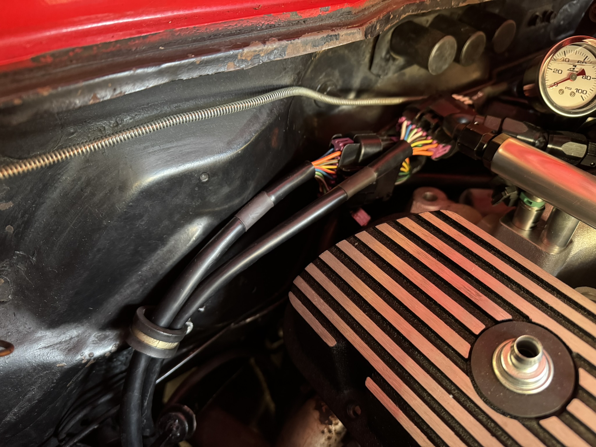
Comments