Wheel alignment is important. No secret, but why do so many people ignore it?
That’s a good question.
Here’s a case-in-point: I went to a couple of different car shows in the last few weeks and saw at least two different cars with the front camber so far off, you could measure it with a yardstick. And I wasn’t talking about some of the tuner crowd either—one was a V8 Vega and the other was a G-Body Monte Carlo SS.
Not only can a huge amount of negative camber make those cars extremely hard on tires, it can also make them dangerous in some situations. (True, a degree or maybe two of negative camber can help cornering—and we’ll get into that later.)
And yes, we’ve discussed setup before. See the following articles
- Rear End Alignment Tech
- 12 Home-Brewed DIY Wheel Alignment Tips
- Understanding & Using Common Wheel Alignment Tools
- The Inside Story on Drag Race Wheel Alignments
We covered a lot of ground with those articles. If you review them, one thing is pretty clear: Alignments are actually easy—there’s no voodoo or hocus pocus here. Shop tools aren’t expensive and anyone who can do righty-tighty and lefty-loosey can handle the job.
In fact, once you get the hang of it, checking and setting wheel alignment (and coming up with a combination that suits your car) can actually prove to be fun. Think of it as if it is a Saturday morning engine tune up, but for steering. That’s what this article is about.
Understanding Wheel Alignment
Wait a minute—aren’t all alignments “by the book?”
Not really.
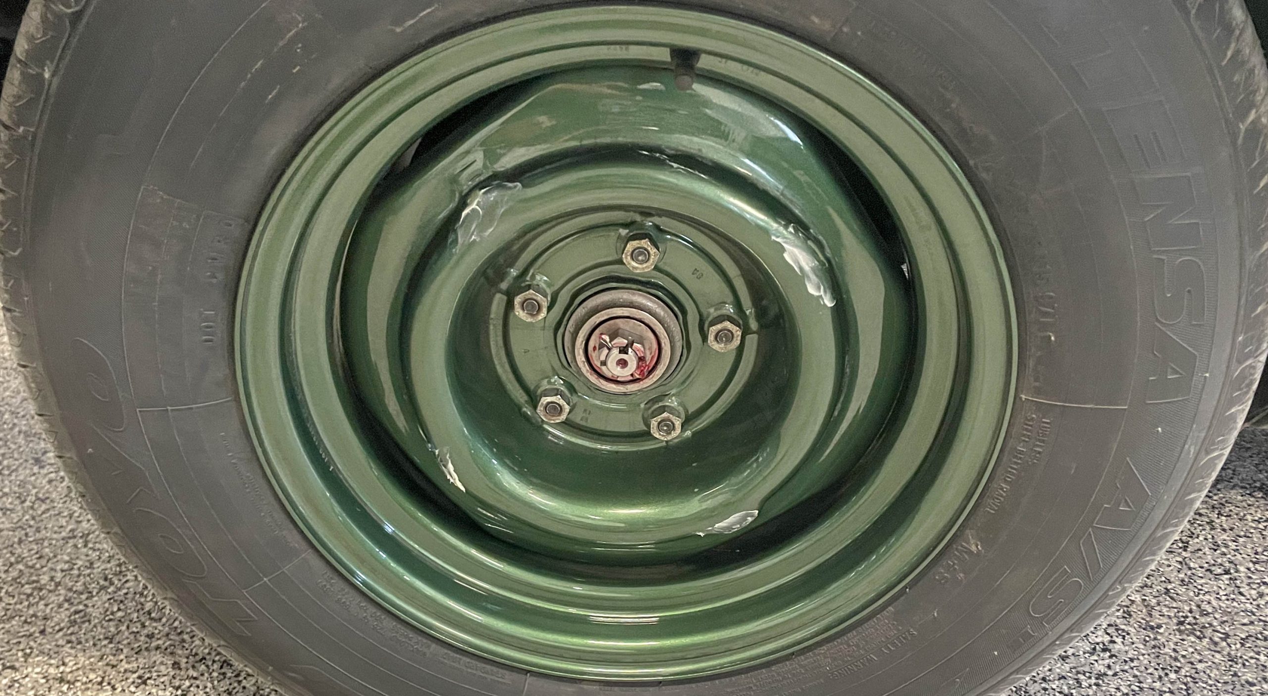
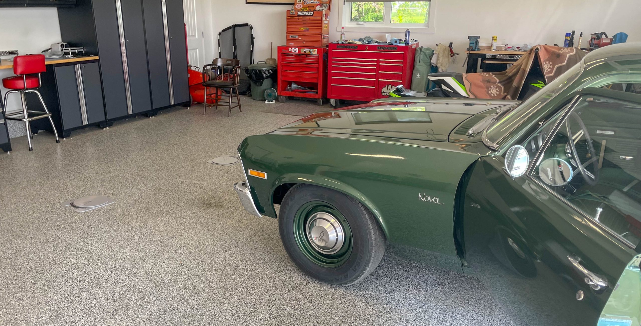
A good example is my 1970 Nova shown here and in the other articles. That car came from the factory with E78X14 bias ply tires. They barely laid down five inches of tread on a 14 x 5 inch wheel. Back then, the front end geometry (including the wheel alignment) was set up so that the car would have a ton of understeer. The manufacturers really just thought it was safer if the driver hammered the brakes, and the car plowed directly into what was in the way instead of spinning out or crossing into oncoming traffic.
Burning through corners or traversing the quarter mile wasn’t in the Engineering Department mindset. Neither were larger radial tires, drag radials, double adjustable shocks, lowered ride height, and tubular A-arms.
The original design team (and most likely, the legal department) just wanted the car to be extremely predictable, easy to parallel park and easy to handle in low speed situations (with or without power steering). And with that, you can see there’s more than likely plenty of room to tailor the wheel alignment for a modified car to suit your personal driving and overall use conditions.
What is Camber, Caster & Toe?
Before we dig into setting options, let’s examine the items you can check and typically adjust with a wheel alignment:
Camber
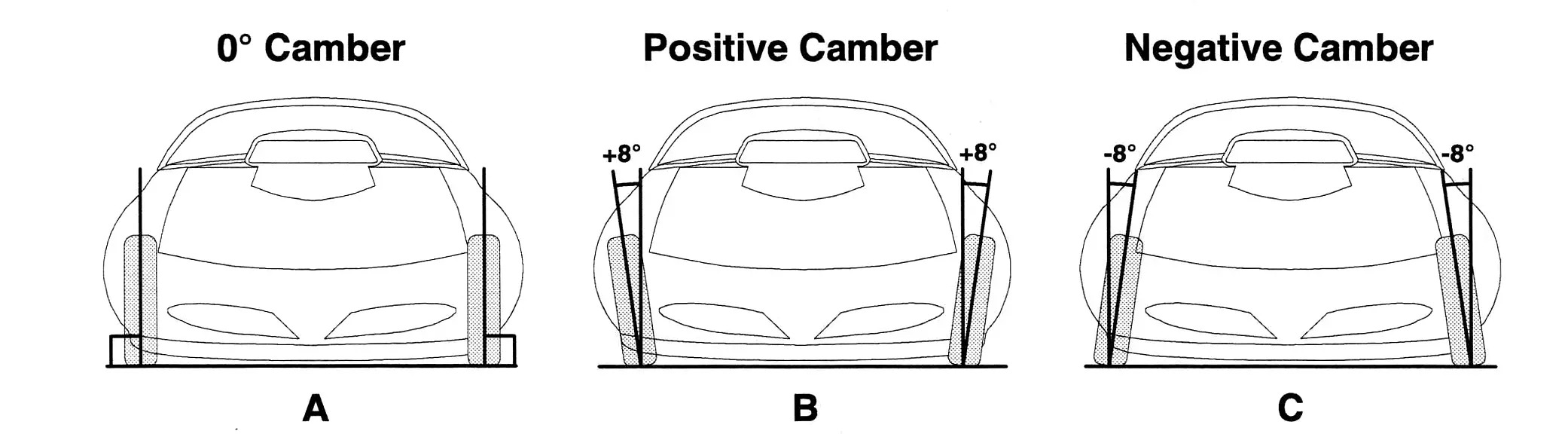
This amount of difference (measured in degrees) between the top edge of the tire and a true vertical line running through the center of the wheel. If the top of the tire tilts inward (viewed from the front) wheel camber is negative. If the top of the tire tilts outward, wheel camber is positive.
Caster
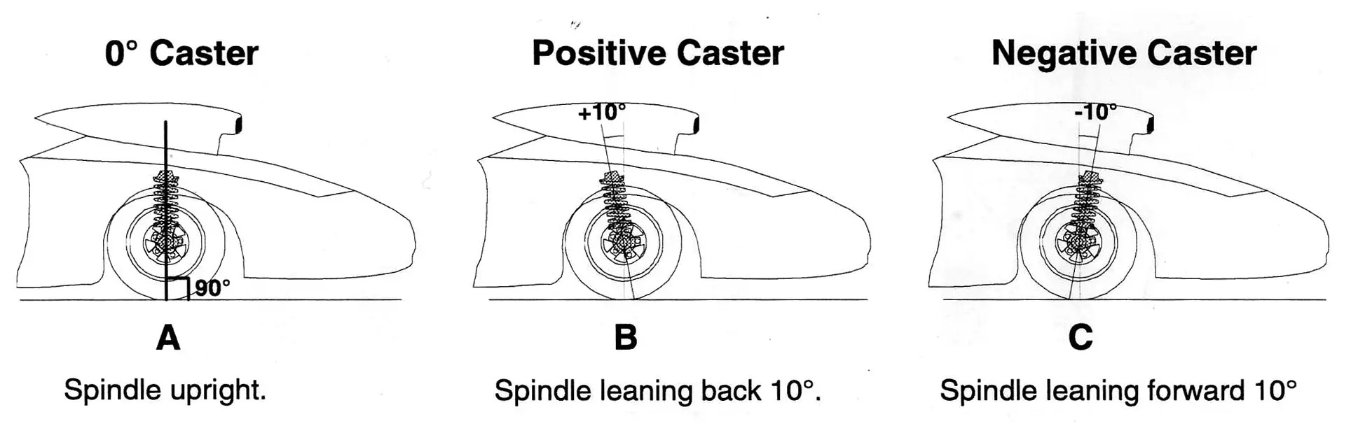
The difference (measured in degrees) between an imaginary line running through the upper and lower ball joints and a vertical line running though the center of the wheel hub to the center of the tire’s contact patch on the ground. Viewed from the side, if that imaginary line tilts toward the rear of the car, caster is positive. If that imaginary line tilts toward the front of the car, caster is negative.
Toe
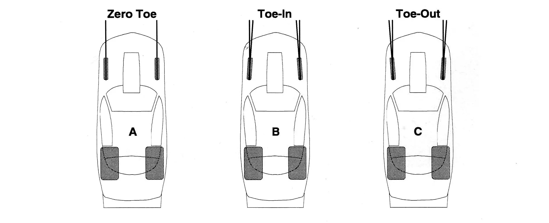
Toe (or “toe angle”) is the difference in track width between the front and rear edges of the tires, viewed from the side. If the track width measures wider at the front, the wheels are toed-out. If the track width measures narrower at the front, the wheels are toed in.
8 Key Elements to a DIY Wheel Alignment
Easy enough. So where do you begin? It’s simply a matter of taking individual steps:
1. Square The Car
First and foremost, the car must be square—see that rear end alignment tech story I mentioned earlier.
Honestly, intentionally setting a car up so that it’s crooked to compensate for the way it works is just wrong (and we’re not talking preload here). Something else in the vehicle is messed up and you should get it right before you continue.
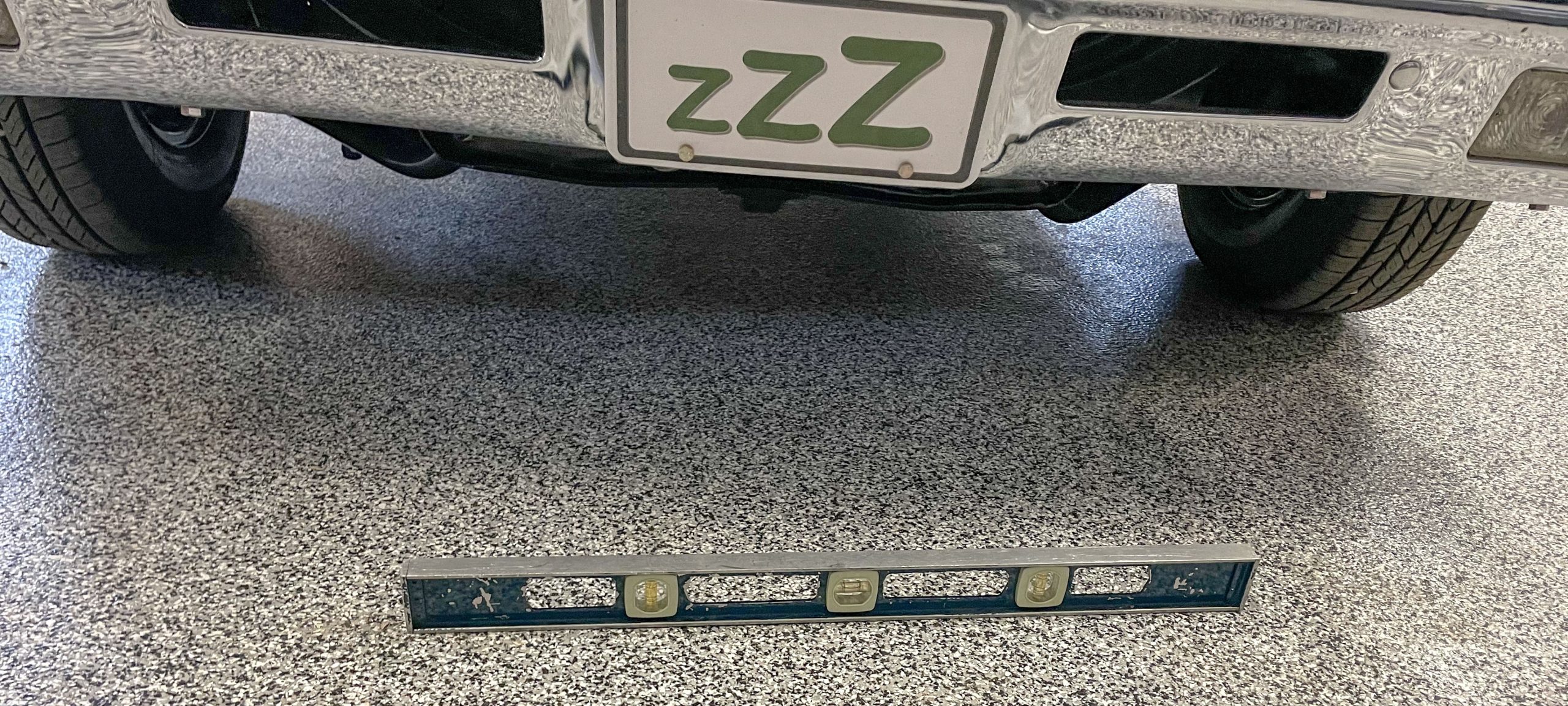
Attempt to locate a level place to work on the car. In my case, I have two shop floor drains and the floor slopes toward them. I do have location close to the front wall where the floor is reasonably flat and that’s where I perform the wheel alignment.
Flat floors aren’t 100% essential though. Many alignment tools are designed to compensate for slightly uneven or non-level surfaces. That’s why circle track racers can easily revise wheel alignments in the pits.
2. Set The Tire PSI & Ballast The Car
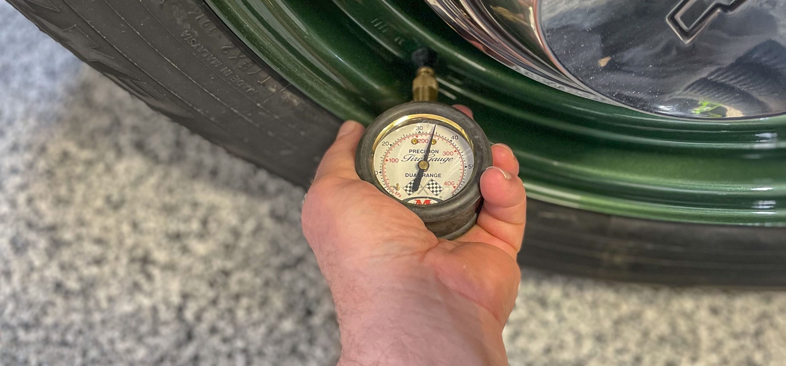
Tire pressure on all four corners should be established. These are the pressures you intend to run.
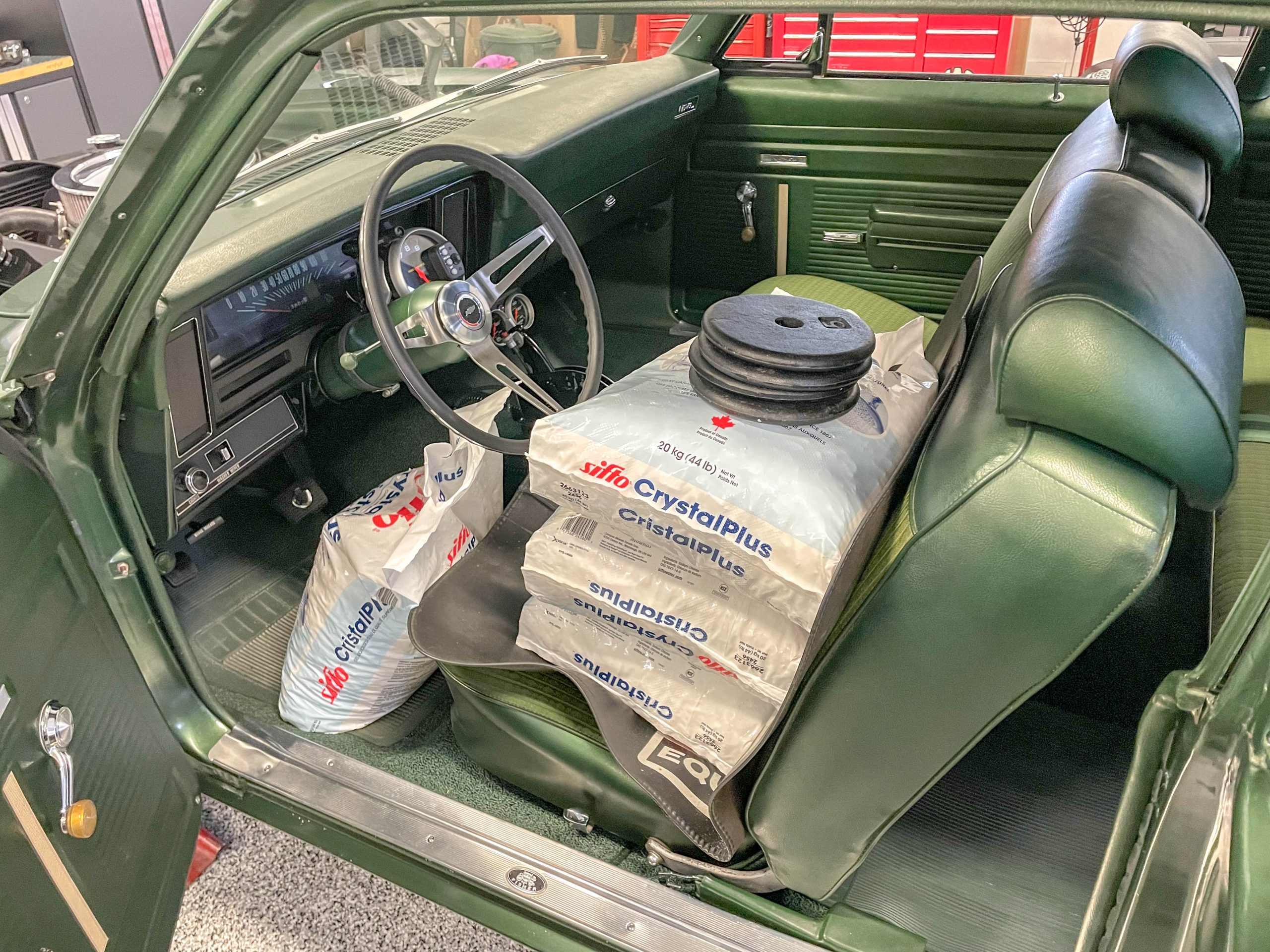
For a race alignment it’s a pretty good idea to ballast the car to simulate the driver in the seat and the correct amount of fuel in the tank. I use water softener salt bags and ordinary exercise weights to nail down the weight distribution.
3. Turning Plates
If you have turning plates, roll the car onto them. If you don’t have turning plates, two vinyl floor tiles stacked together per side work great. The trick here is to sprinkle table salt between the two tiles. That allows them to turn independently.

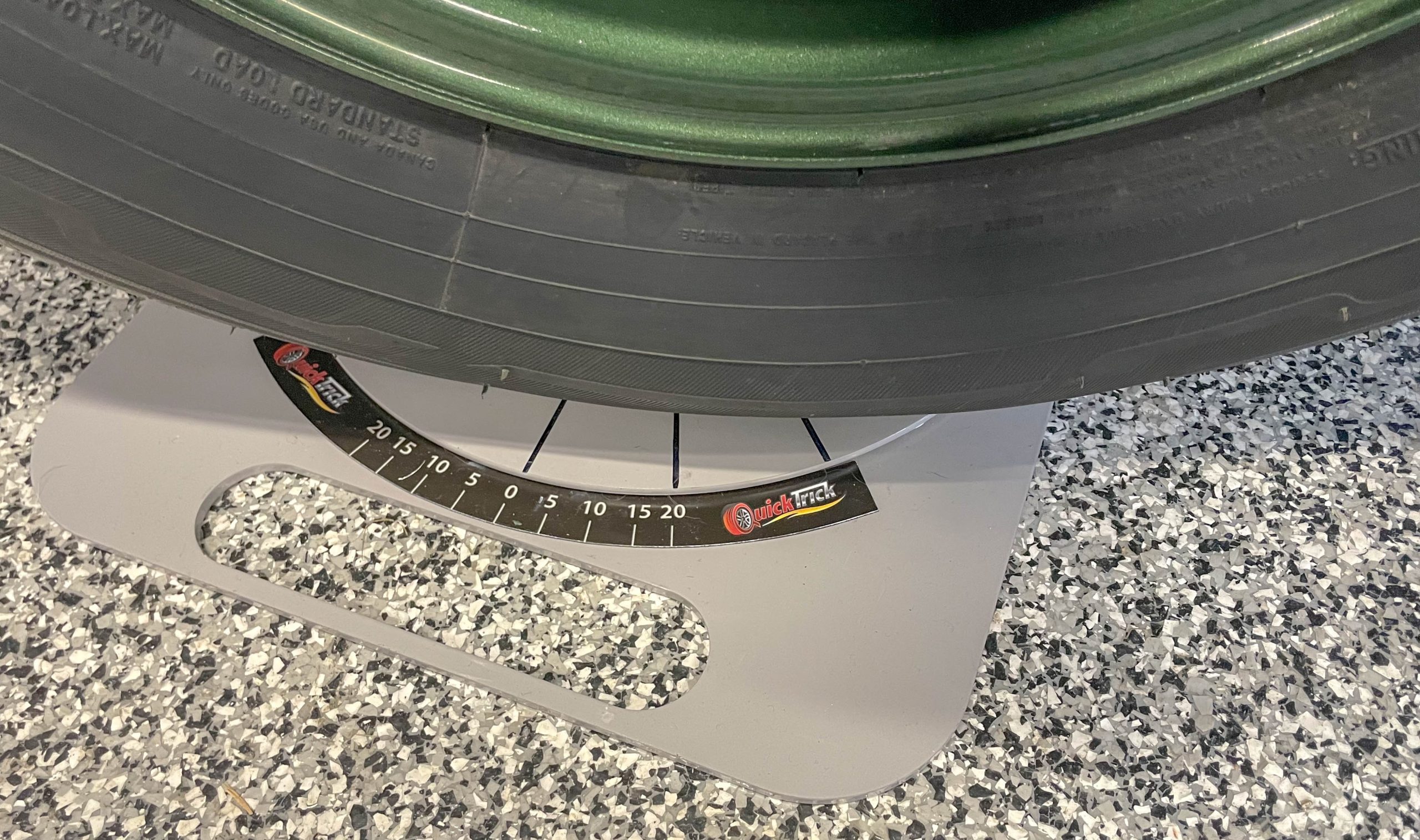
As mentioned in previous articles, I tried oil between the tiles to reduce friction. It failed miserably. In the end it just makes a big mess. Table salt does a better job. I now use the thin bearing-equipped turning plates from QuickTrick products.
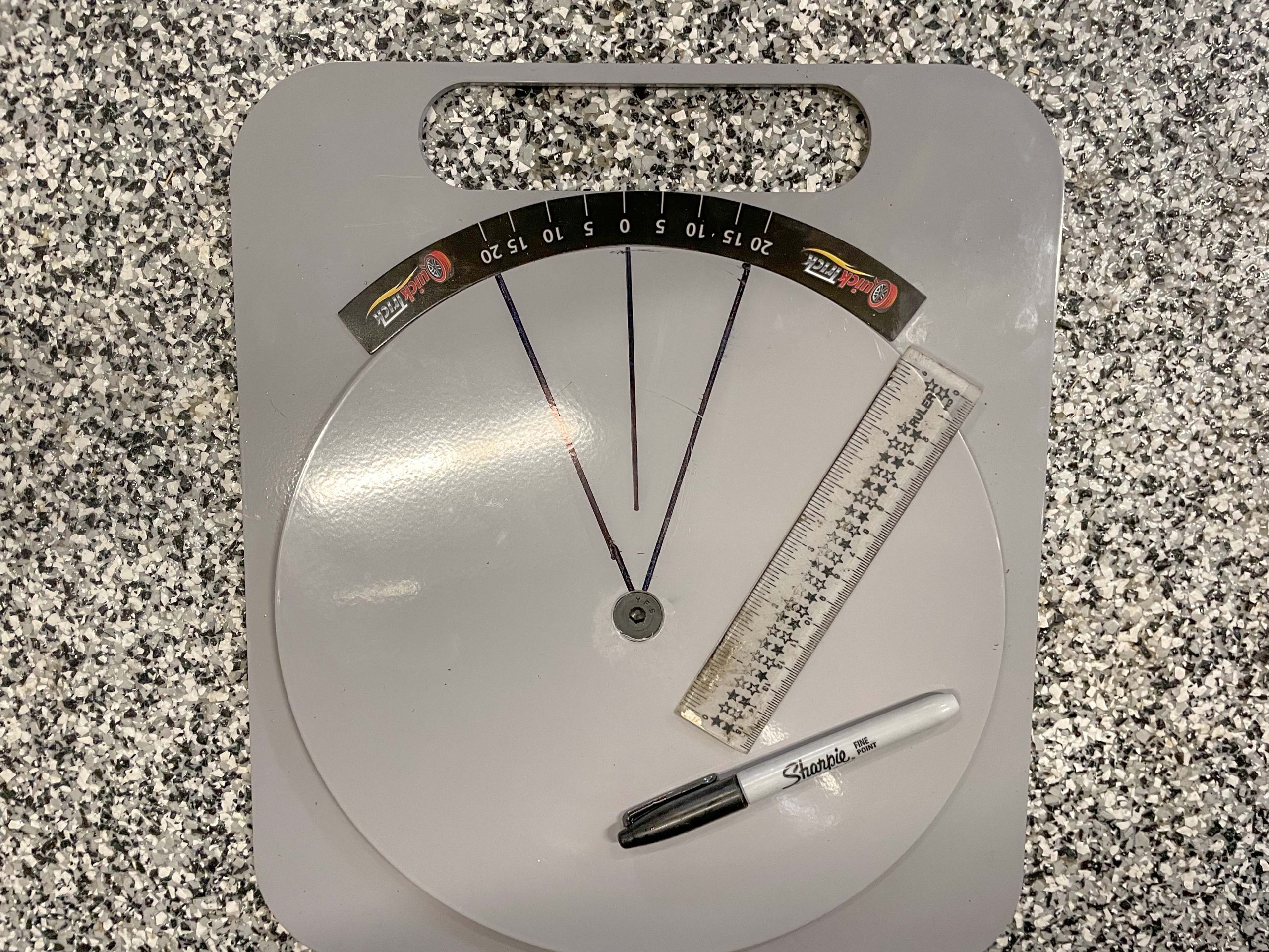
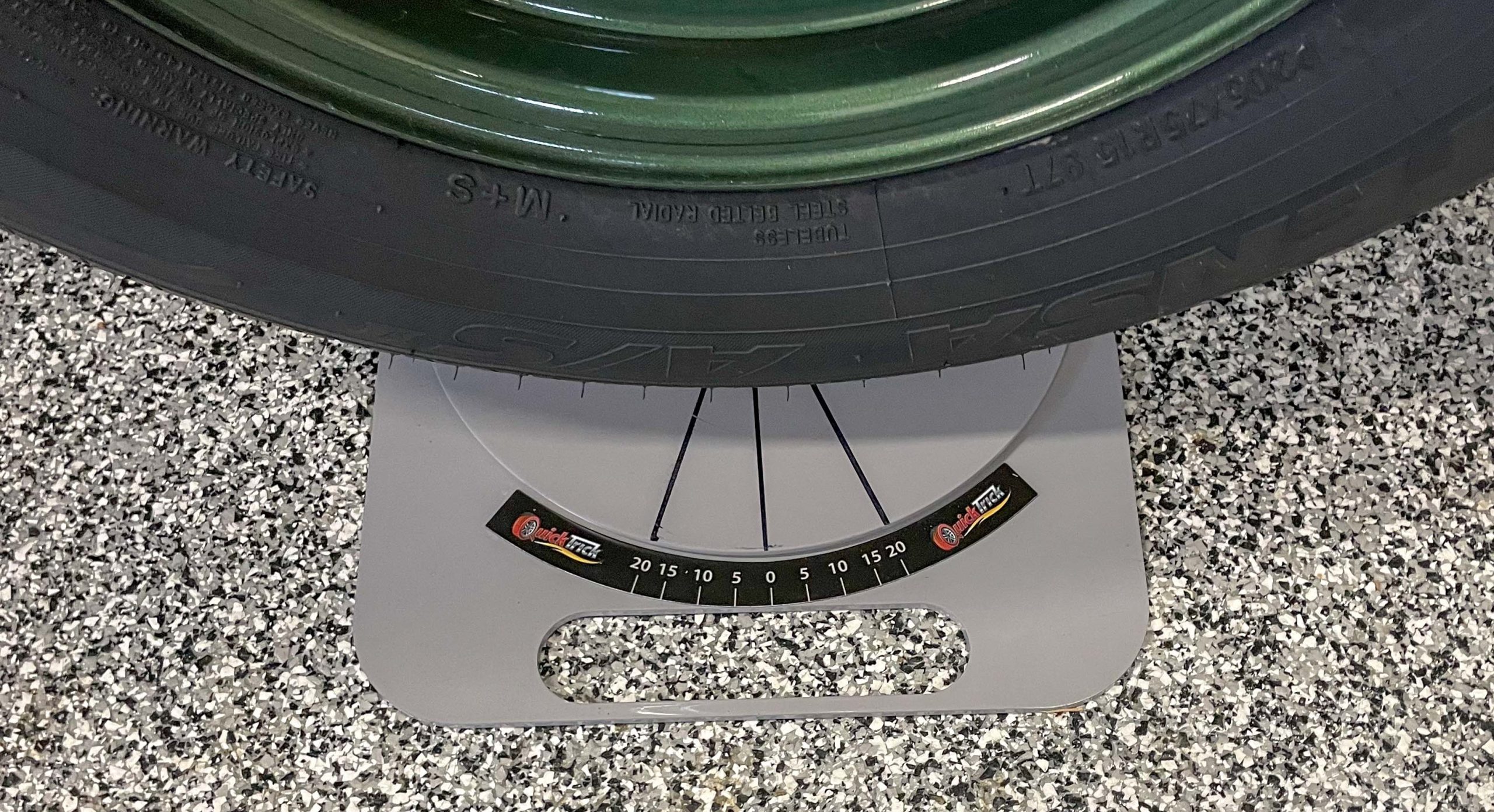
When using turning plates of any sort (store-bought or home-made), you’ll have to establish and mark the centerline of each wheel on the plate. In some situations, you’ll also need to mark 20 degrees on either side of it. The QuickTrick turning plates include a magnetic scale with degrees marked on it, but it is still necessary to mark the center line of each wheel.
4. Steering Centered
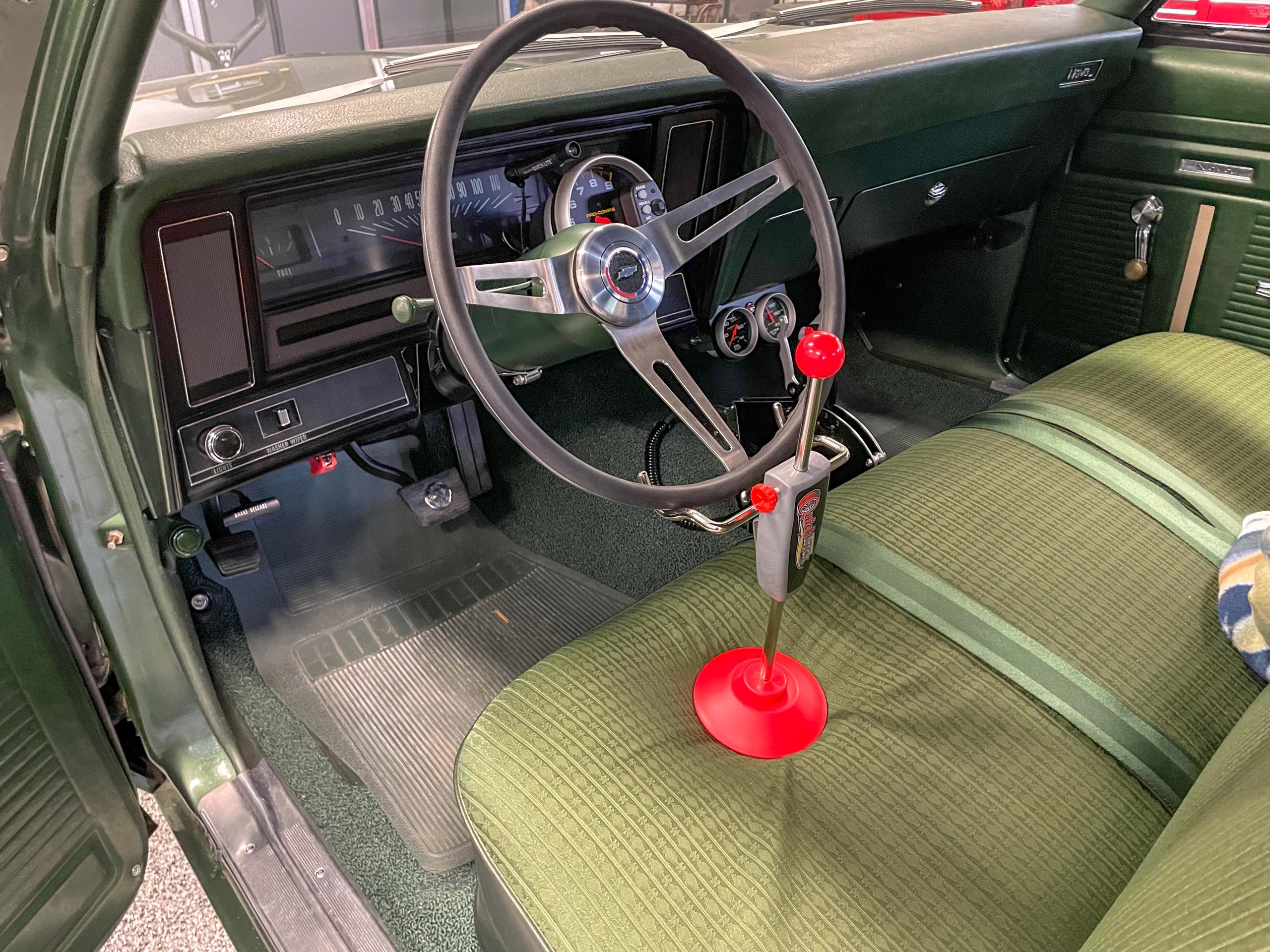
Center the steering wheel and if you have a steering wheel holder setup, install it. I use an inexpensive steering wheel locking device from QuickTrick products. It simply positions on the seat and clamps the base of the steering wheel. It extends vertically to take up the slack. When extended, the tool effectively locks the wheel straight ahead, plus there’s zero damage to either the wheel or the seat.
If you don’t have a steering wheel lock, you can move the seat all the way forward and jam a helmet between the steering wheel and the seat. Don’t laugh—it works!
5. Ride Height
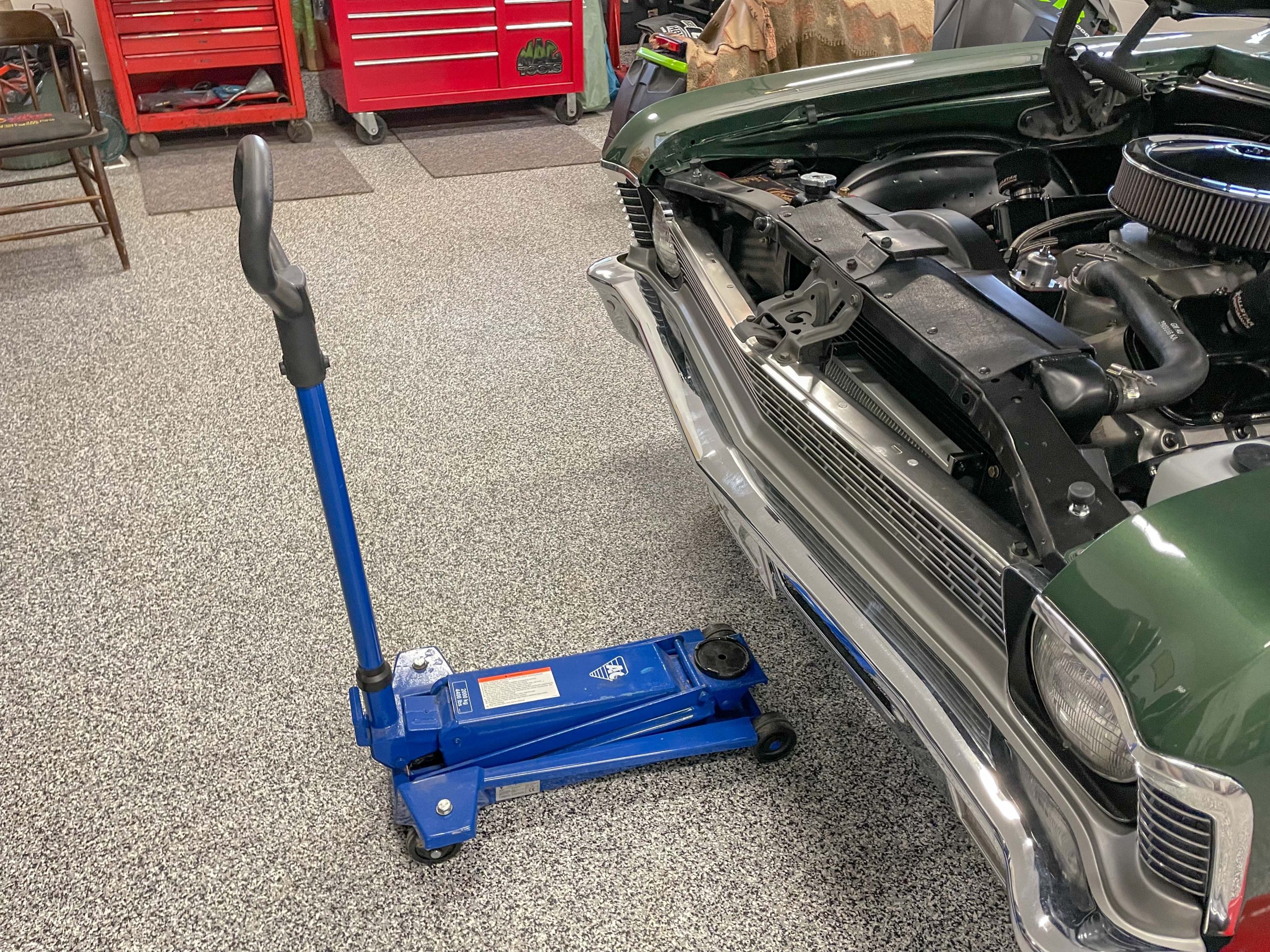
Measure the front ride height. I just check the distance from the front fender wheel well lip to the ground. The reason for this is, because I personally like to check the wheel alignment when the car is at settled ride height and again when it is raised up 1.5 (or so) inches. This allows for a comparison in wheel alignment when the car is accelerating.
By the way, the 1.5 inch ride height change is an arbitrary number. If you have a race car with an onboard data collection system computer, you can use optional sensor modules to determine ride height changes. I don’t a data collection device, hence the arbitrary “guesstimate” 1.5 inch number.
6. Camber
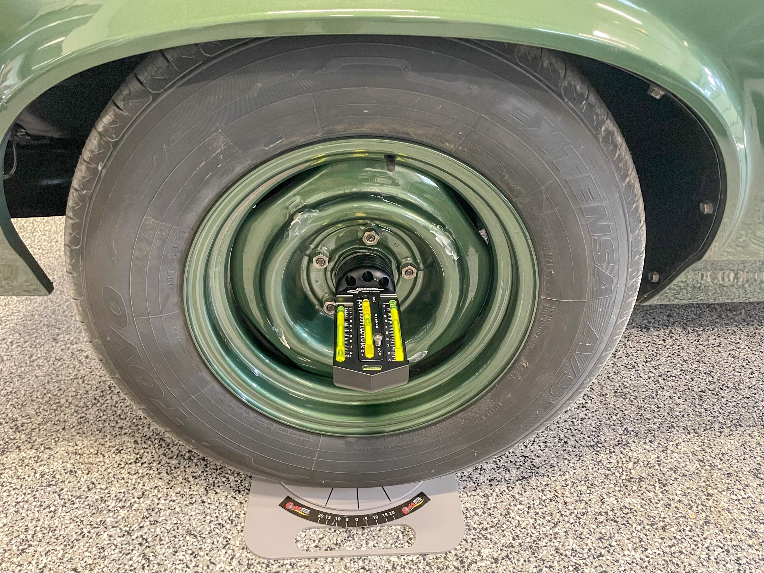
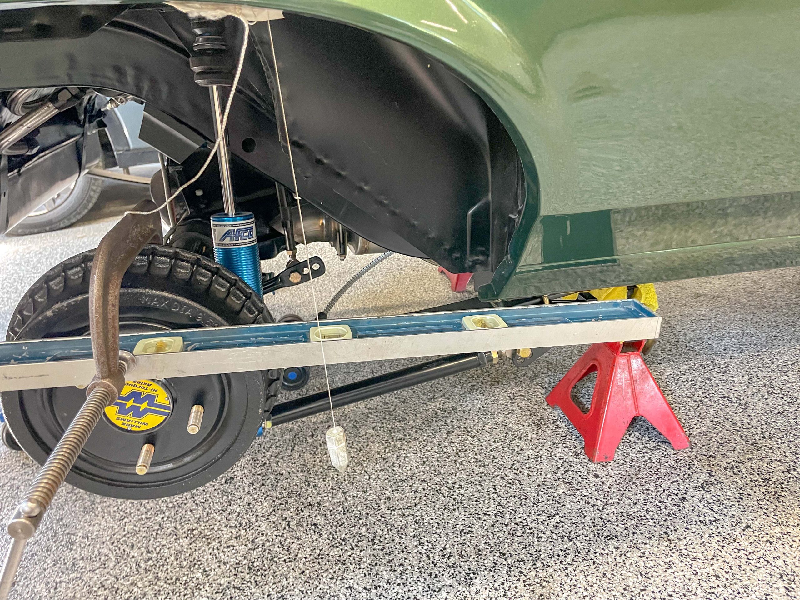
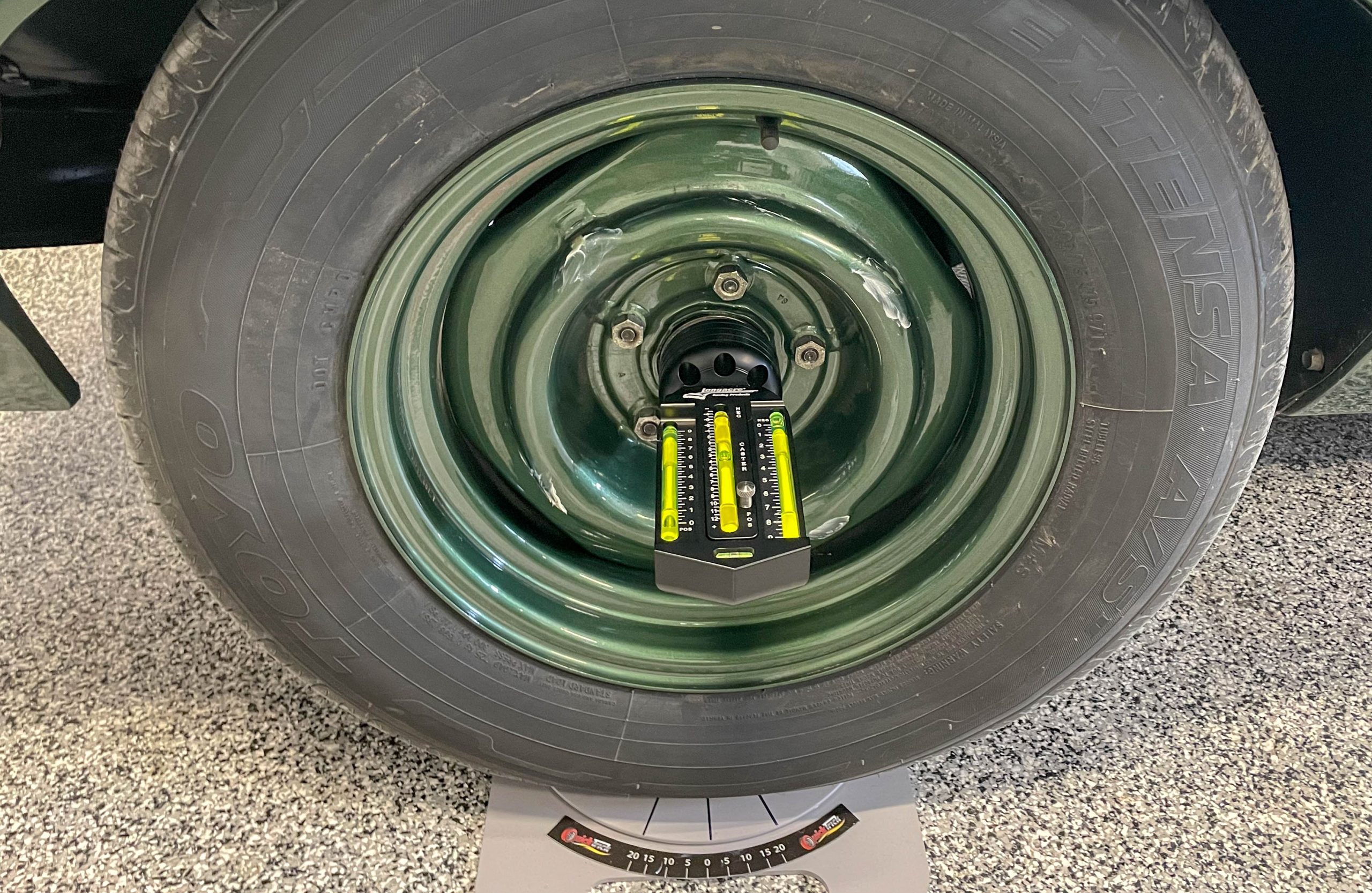
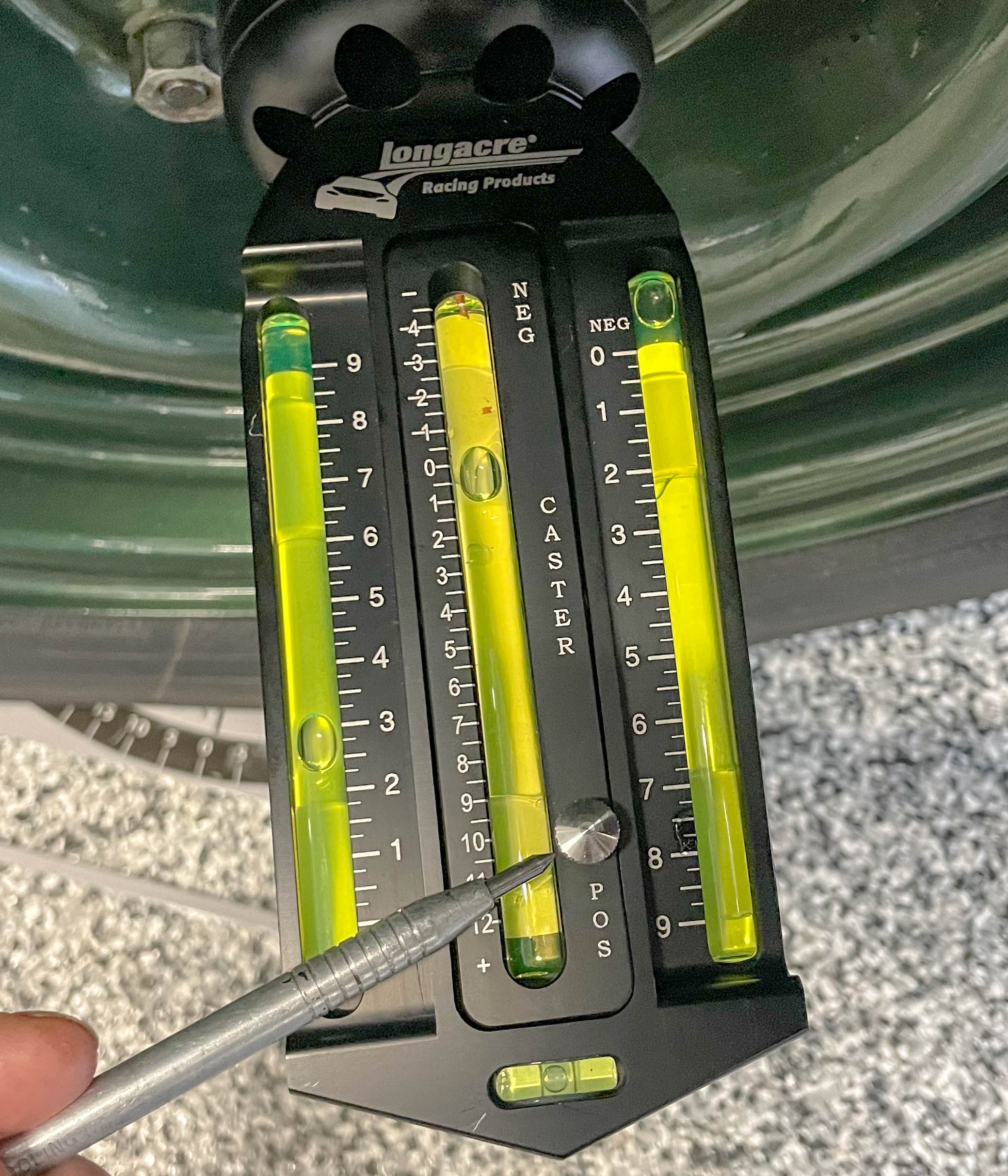
Check and set the camber. I have two different tools to accomplish this: a digital system from QuickTrick Products, and a conventional bubble level gauge from Longacre Racing Products.
Here, I believe the big difference between the pair is setup time.
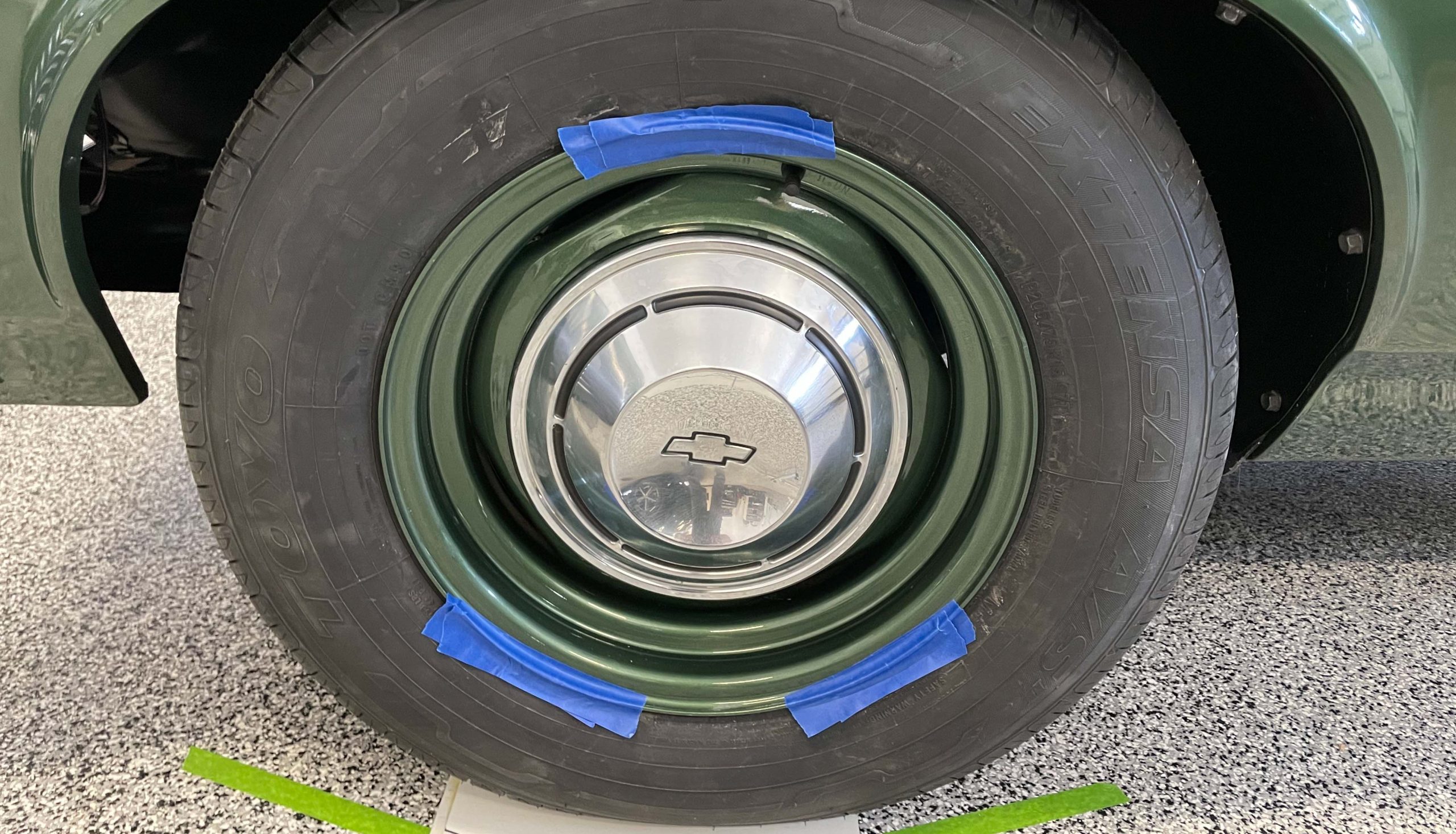
The QuickTrick system relies upon aluminum toe bars affixed to the rim edge of your wheels. On the other hand, the Longacre gauge is installed by removing the wheel hub cap and the spindle dust cover. It uses a magnetic adapter to attach directly to the hub.
In use, I find the Longacre gauge is far easier to set up and use. Results between the two are close though.
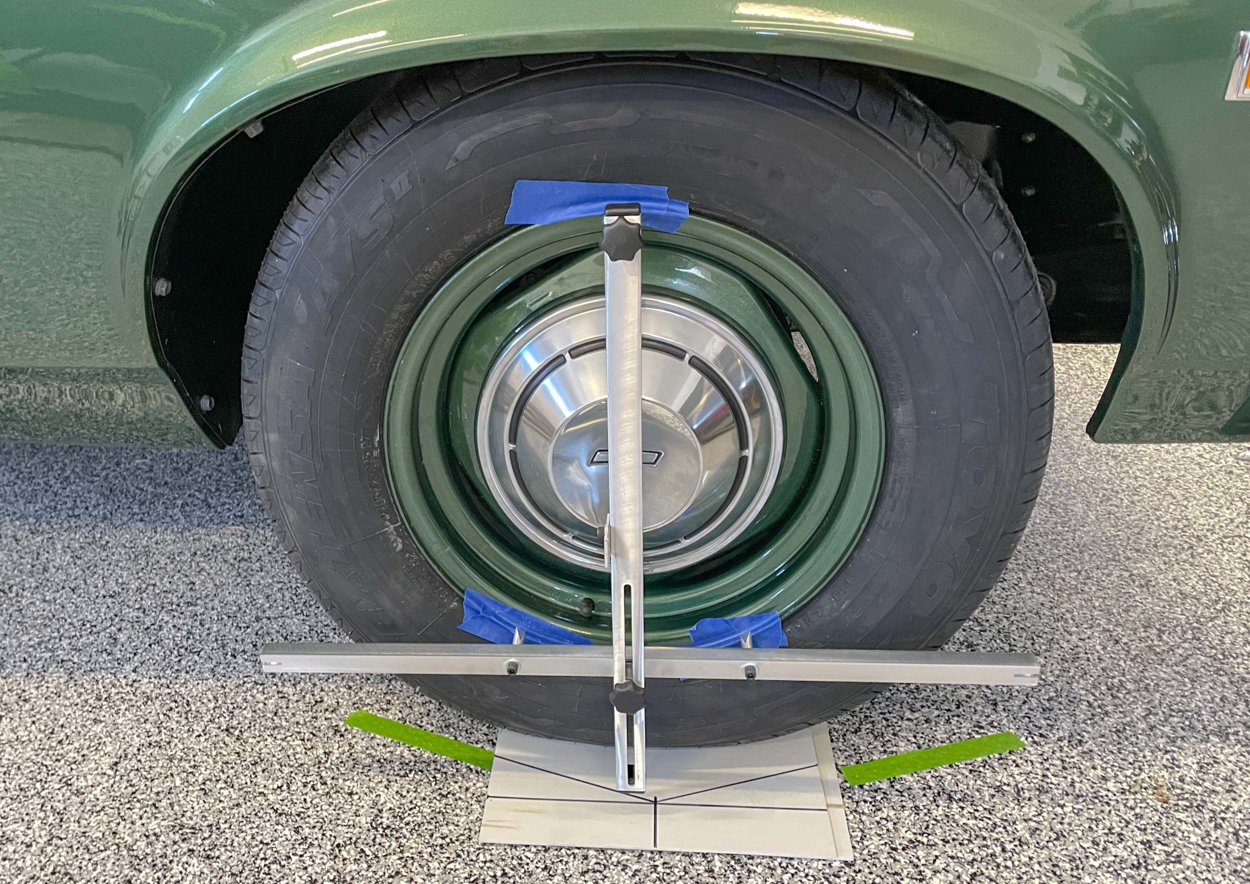
Using the QuickTrick digital system, you first setup and install the toe bars—one on each side of the car. Then each digital gauge is placed on the ground in front of each front tire. Both gauges are then zeroed (this compensates for an uneven surface).
From here, the digital gauge is attached to the respective toe bar, ensuring it’s square.
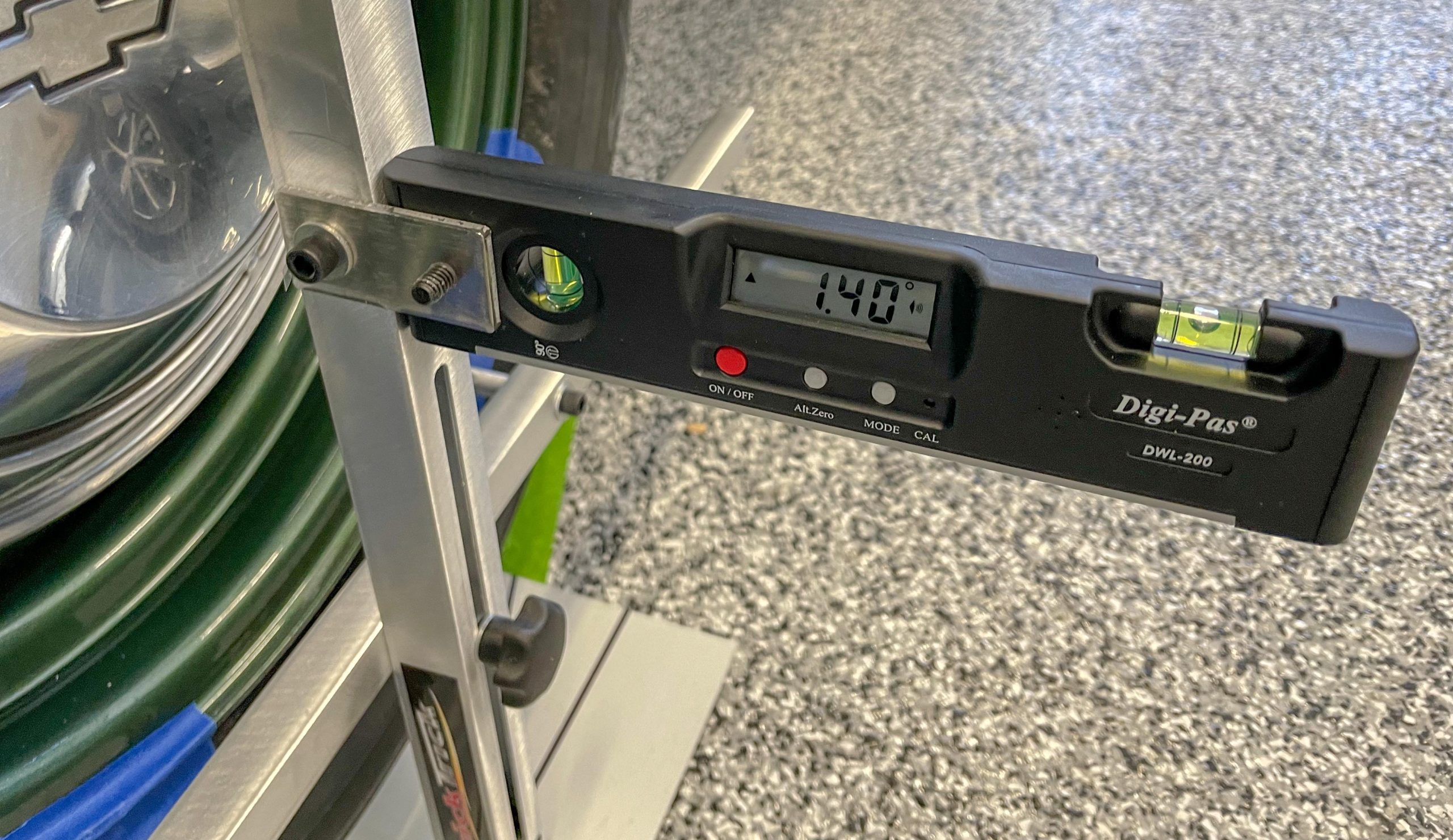
At this point, the gauge will read an “up” arrow indicating positive camber or a “down” arrow indicating negative camber. Each digital gauge is extremely accurate and measures to 1/10th of a degree.
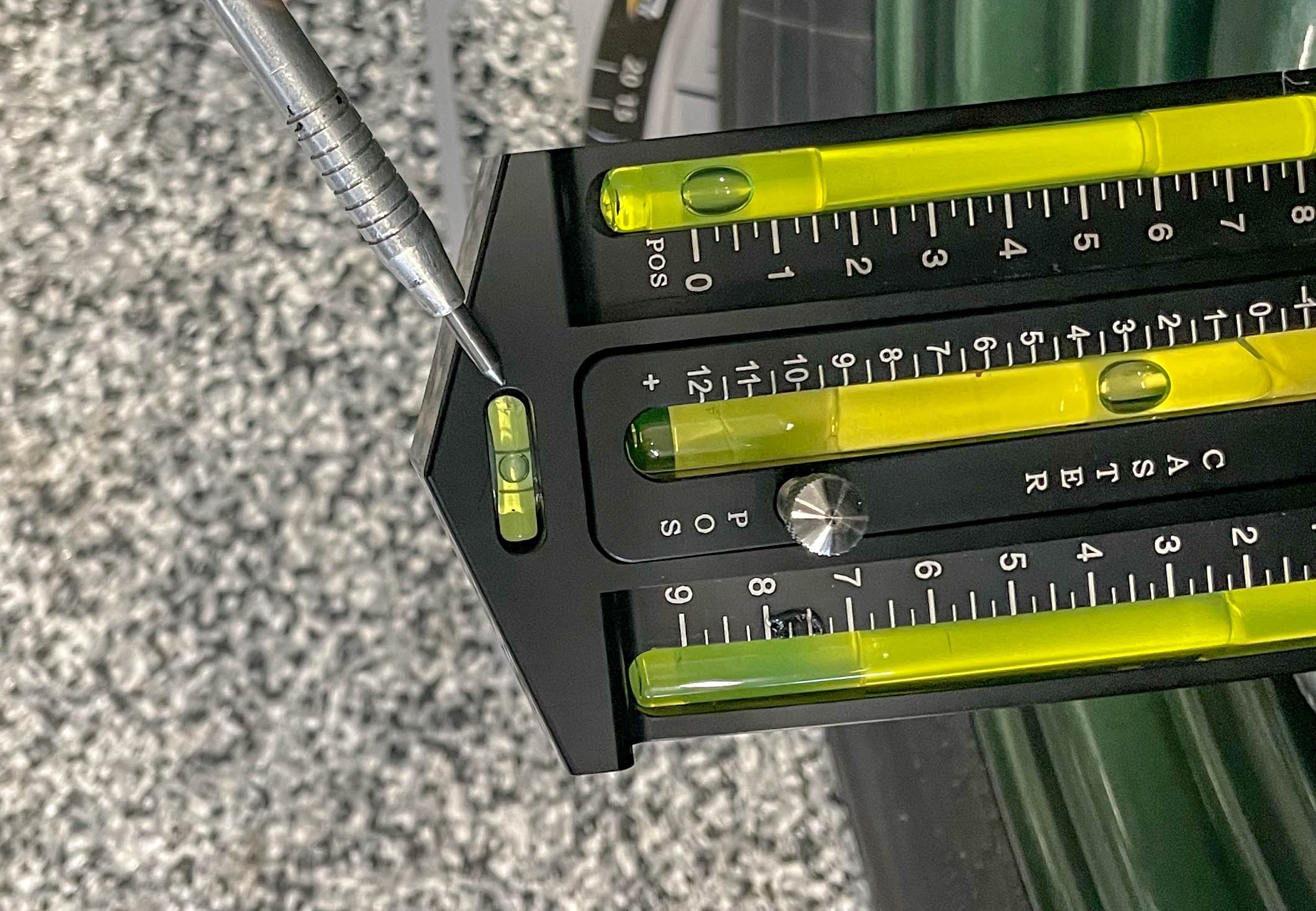
In contrast, with the Longacre gauge you simply rotate the gauge until the small vial at the end shows level. Then you read the camber directly on one of the two vials on either side of the gauge. They’re marked “+” or “-“.
Read the line nearest the center of the bubble—it’s all very simple, although it may not be quite as precise as a digital system.
To adjust camber on many older cars such as the writer’s Nova, shims, located between the upper A-arm cross shaft and the subframe member are added or subtracted in equal amounts.
Theoretically, one 1/8 inch thick shim works out to approximately 1 degree of camber. Keep in mind that is just theory and in practice it may be different for your application.
In setup, if one side of the front suspension ends up with a camber angle that is different from the other side, the car will tend to pull toward the side with the greatest positive camber. Some folks set their cars up this way to compensate for the road crown. Compensating for the road crown can also be accomplished with different caster setups (see the next section).
Note: Shims aren’t the only way to set wheel alignment. Some cars use eccentric (cam shaped) fasteners for adjustment. Others (with struts) can make use of adjustable caster/camber plates for adjustment. Some incorporate a strut rod to set caster. And there are other methods too.
7. Caster
Checking caster is next. It’s slightly more complex, but still well within the realm of the home hot rodder.
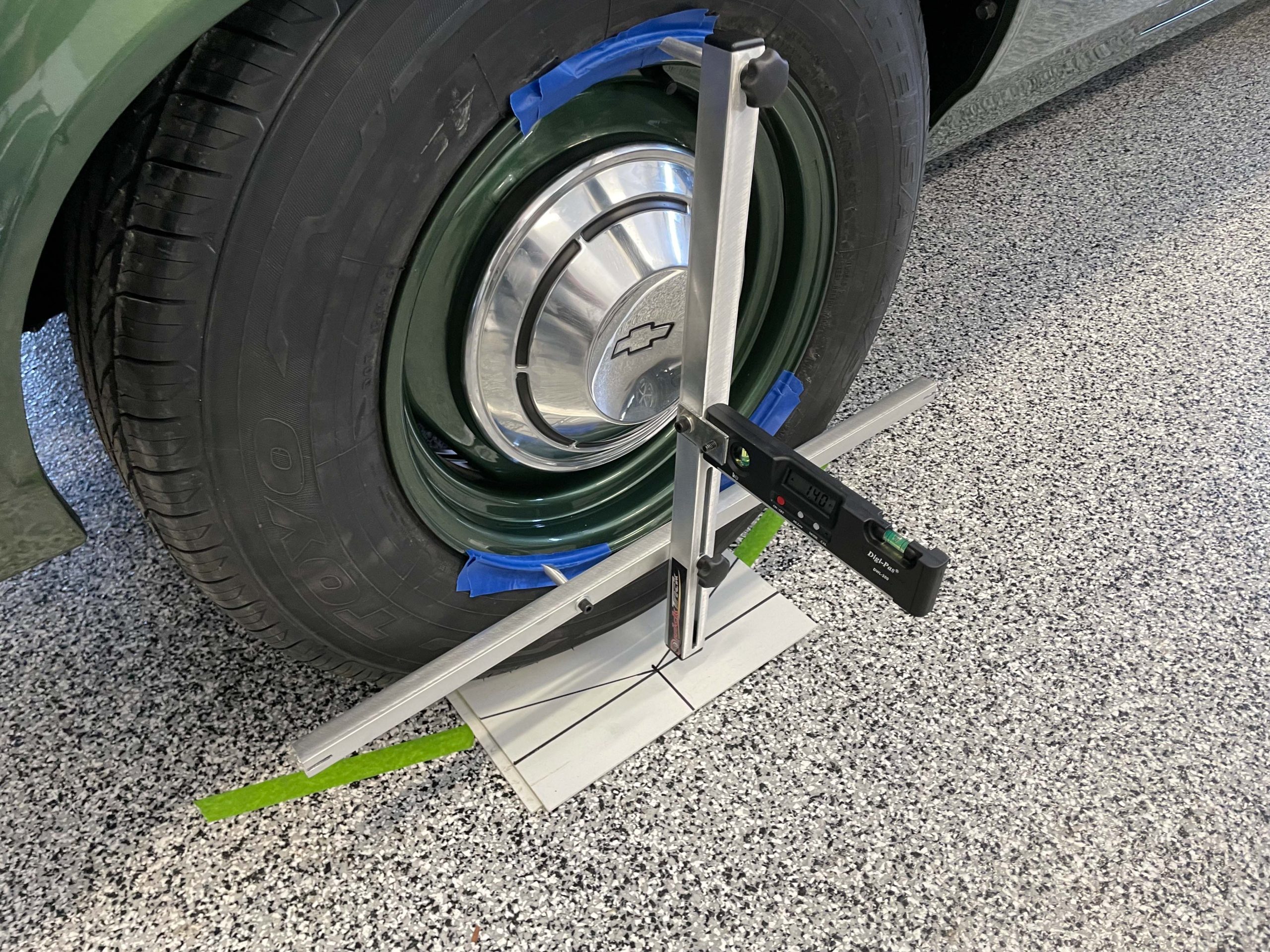
Here’s how it’s accomplished with the QuickTrick alignment system: With the QuickTrick alignment frame mounted on the wheel you’re measuring, set the gauge for degrees (it’s a mode for the gauge) and check to ensure the alignment frame upright is vertical. Double check the steering. It should still be straight ahead.
Install the digital gauge on the QuickTrick vertical bracket. Release the steering lock and turn the steering so that the wheel you’re measuring is at 20 degrees on the turning plate. Zero the digital gauge. Next, turn the steering back to center and then an additional 20 degrees in the opposite direction. Read the digital gauge. A wee bit of math is involved here: Multiply the reading on the gauge by 1.5. That’s the caster measurement.
Repeat the process on the opposite side of the car.
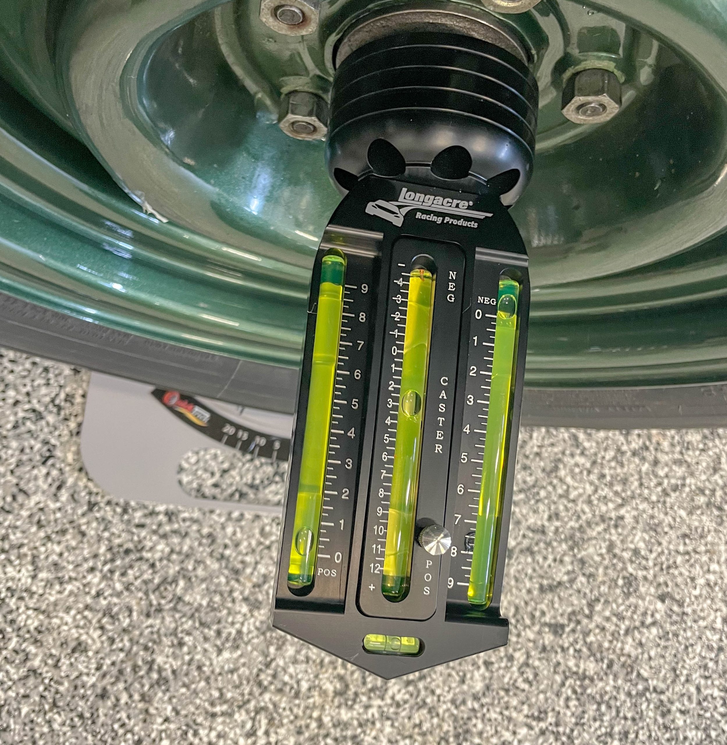
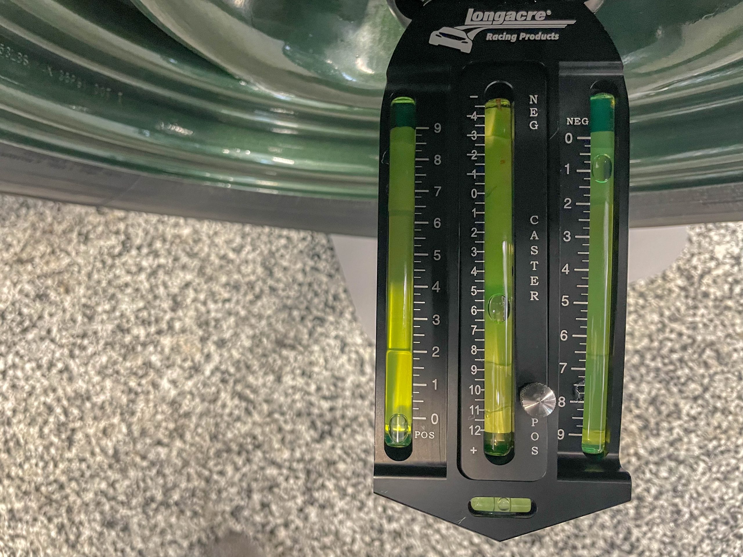
With the Longacre caster/camber gauge, caster is set by first turning the front wheels 20 degrees to the right (when setting the right front) and 20 degrees to left (when setting the left front). This must be done accurately. Turning plates are ideal, but if you don’t access to them, the angles machined into the corners of the gauge can be used as a reference. Here, you turn the wheel until the angle of the gauge is parallel to the side of the car.
Next, rotate the gauge on the hub until the end bubble shows level. Twist the knurled knob in the center of the gauge so that the middle vial reads zero-degrees. Turn the steering back to center and then an additional 20 degrees in the opposite direction. Read the caster directly on the center vial. Each hash mark on the vial is half a degree.
Repeat on the opposite wheel.
By the way, the 20 degree figure isn’t absolute. It’s commonly used because the more the degrees the wheel is moved left and right, the more accurate the measure becomes. If you choose a different figure, just be certain it’s the same left to right, and side to side.
Longacre Racing notes that each time you make a change in the front suspension settings (adding or removing shims), it’s a good idea to bounce on the front end to settle the suspension. Adjusting the caster can have an effect upon camber and vise-versa.
Once you set caster, it’s a good idea to recheck camber.
In order to adjust caster on a car like the Nova in the photos, shims are added or subtracted from each end of the A-arm. For example, positive caster is established by either adding shim(s) to the rear bolt on the cross shaft or removing shim(s) from the front bolt on the cross shaft for the upper control arm. One 1/8 inch shim moved from one end to the other on each shaft will change caster approximately one degree. At least, that’s the theory but again, it doesn’t always hold true.
FYI, caster is more easily set with the Detroit Speed uppers shown in the photos. They make use of replaceable alignment slugs that fit into machined openings in the upper a-arm cross shafts. To fine tune the setup, you can still juggle shims front to back.
8. Toe
Before you check and set toe, roll the car back a few feet off the turning plates and roll it back on. This must be done every time you set toe.
Some folks claim rolling it back and forth isn’t necessary when using turning plates, but we do it any way—it’s not tough.
The reason for rolling the car back and forward again is to load the tires which in turn, provides you with the most accurate numbers. Toe is the last thing to set because making an adjustment on the a-arms for caster and camber moves them. This has an effect upon toe.
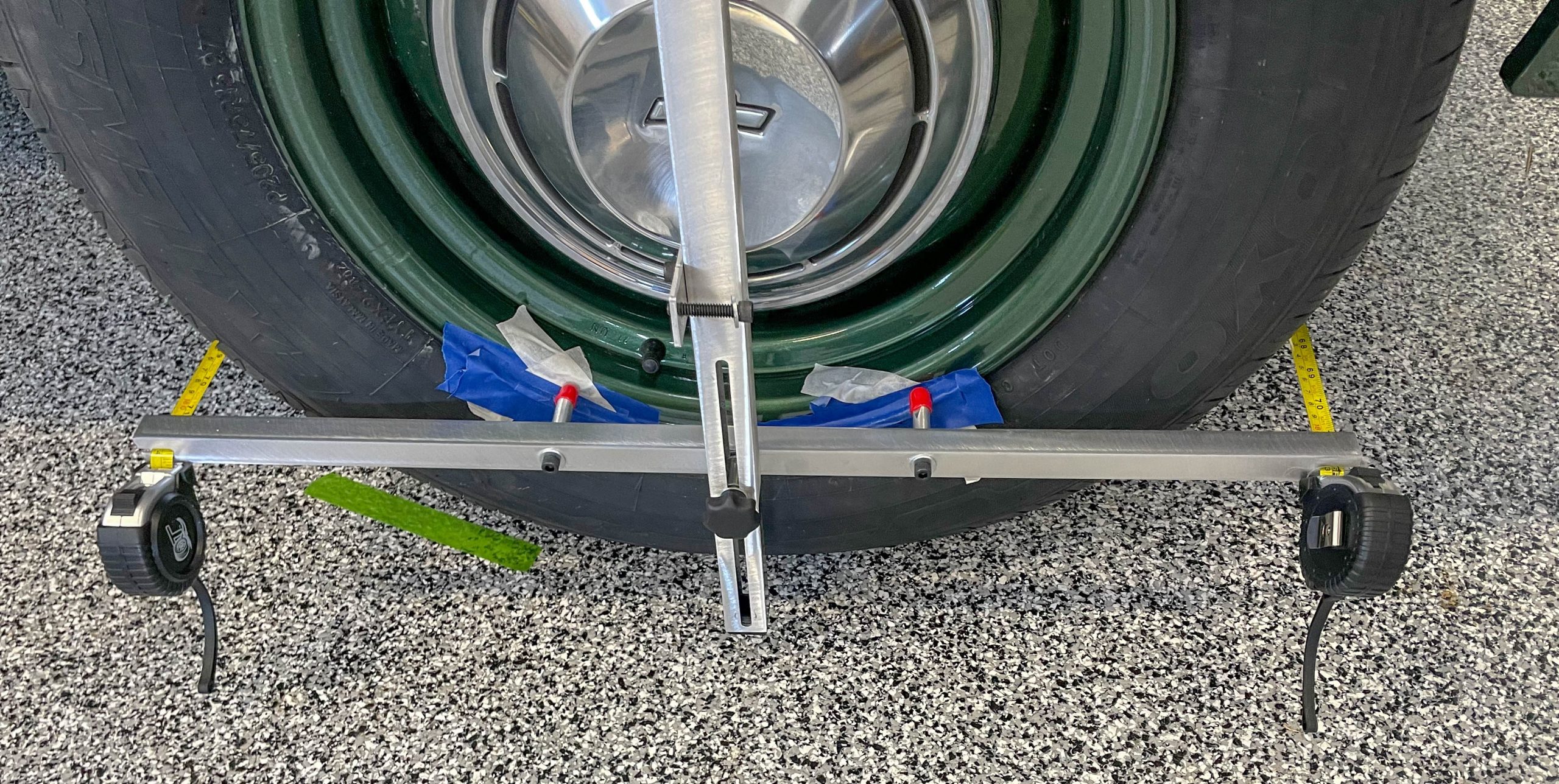
First, point the steering wheel straight ahead and re-install the steering wheel locking tool. In order to check toe with the Quick Trick tool (set up on each side of the car), slide a tape measure into each of the slots cut into the alignment frame.
One tape measure is positioned ahead of the front tires, and another is positioned behind the front tires. I typically use masking tape to hold the clip of each tape measure in the slot. This ensures the clips on each tape are seated in the slot.
Gently extend the tapes (simultaneously) and carefully read the tape measure. If you have a larger measurement number in the front, this means you have toe out. If the rear measurement number is larger, then you have toe-in.
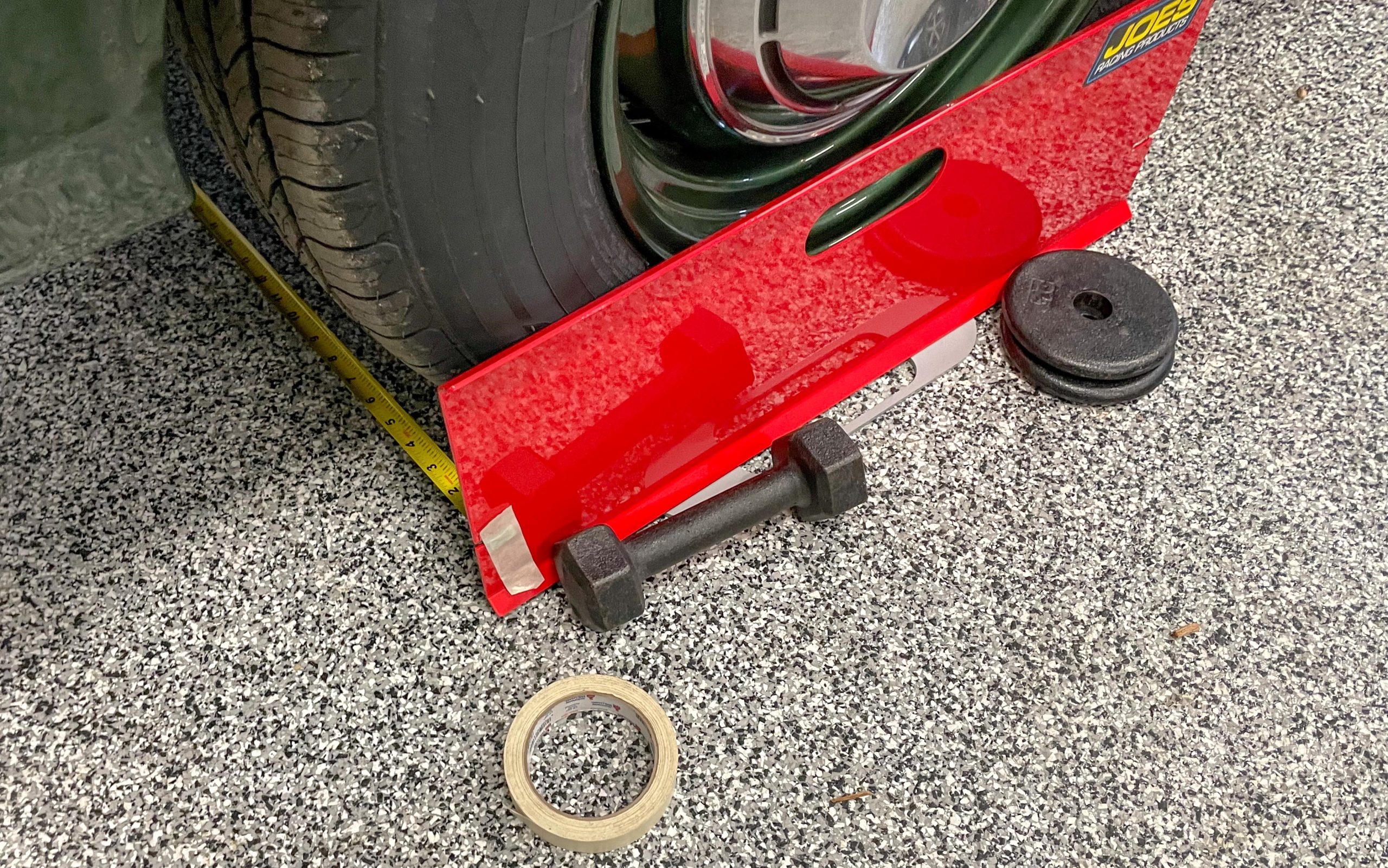
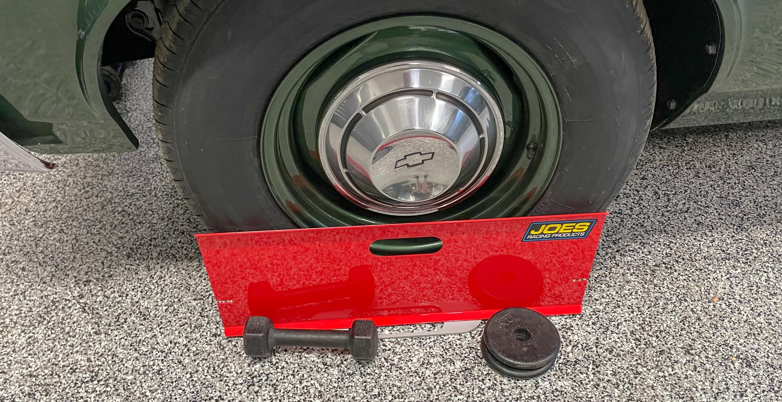
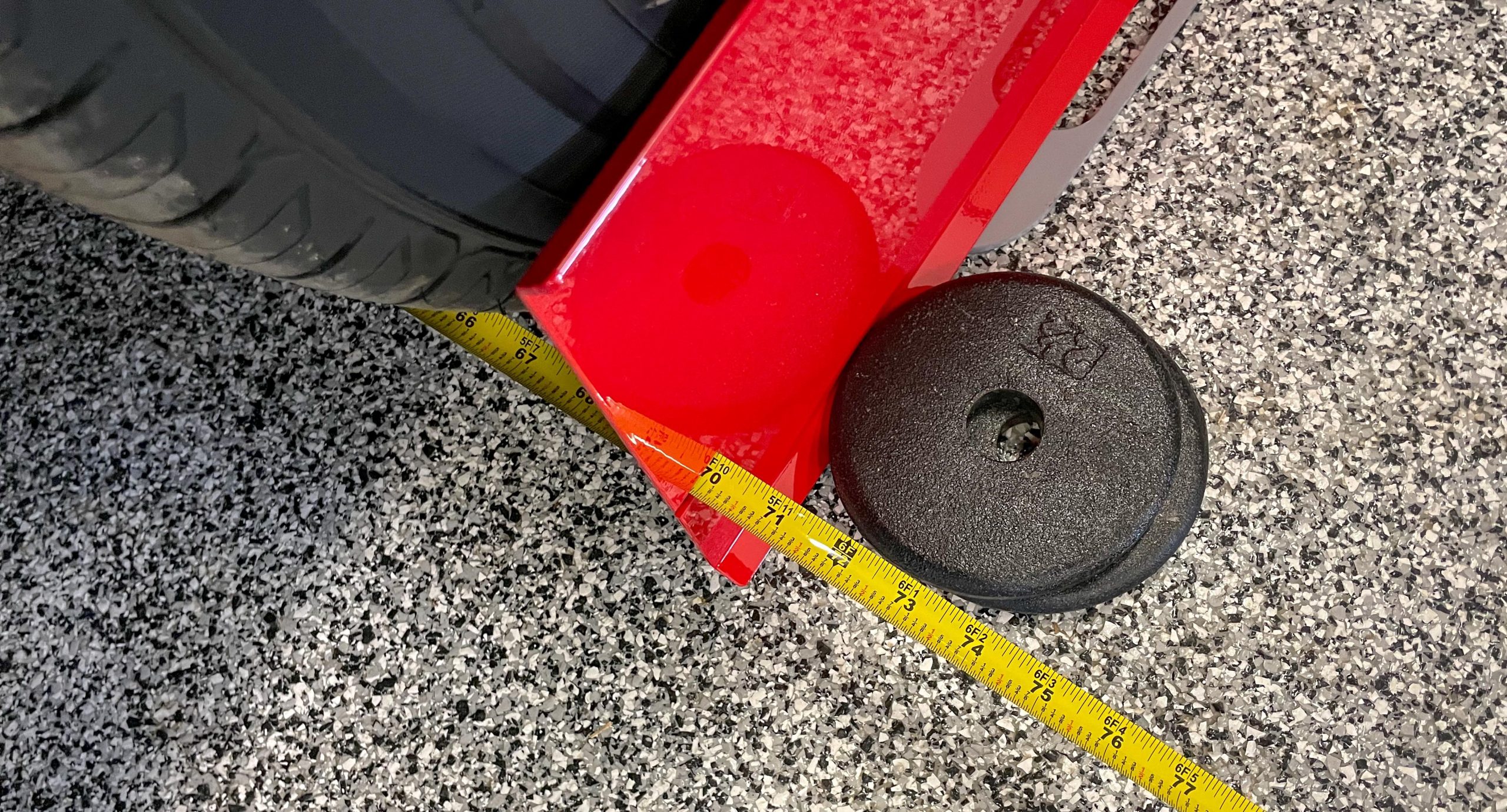
I also use Joes Racing Products toe plates. This setup is even easier to use. Each toe plate is propped up against each front wheel. I use an ordinary gym weight to keep the plates propped up identically (side to side). Then it’s a simply matter of using the supplied tape measures to check the toe.
In order to change toe settings, you have to loosen the jam nuts on the tire rod adjustment sleeve (between each tie rod end). The jam nuts are right and left hand thread. It’s a good idea to adjust each of the tie rod adjustment sleeves equally in order to come with the final toe setting. I simply count the threads to make sure they’re close.
Some Alignment Reference Specs
At this point, you’re done. But what are some typical “custom” alignment specs?
With my Nova, I tend to use a small amount of zero to negative camber and almost 6 degrees or so of positive caster and I use less than 1/8 inch of toe-in. This tends to make the car stable at speed and a little bit of negative camber helps the car when it’s turned in or out. I don’t worry much about the difficulty in parallel parking the car. It’s certainly not a daily driver.
For something like a first-gen Camaro autocrosser, something like 1.5 degrees of negative camber, 5 degrees or so of positive caster, and approximately 1/8 inch of toe works well, though this setup will eventually wear the edges of the tires.
By the way, you’ll need aftermarket A-arms for the both of the above settings. You’ll never come up with 5 degrees positive caster with a bone stock first gen Camaro A-arm arrangement. Here, you might be lucky to come up with 2.5 degrees of positive caster.
Other Factors to Think About
Something else to consider is cross caster. Some production cars were built with more positive caster on the passenger side. The reason for this is the crown in the road. A tiny bit more caster on the passenger side will keep the car from pulling toward the right ditch.
Bump steer is a topic all by itself, but in brief, you might encounter it in a car with a heavily revised ride height (for example, heavily lowered). Essentially you’ll know you have it if you hit a bump, the suspension compresses and the steering wheel moves by itself. It’s caused by the control arms and the steering linkage traveling through arcs that do not have equal radiuses. What happens is the toe changes as the suspension goes through its travel.
Bump steer can sometimes be fixed simply by readjusting toe. But if that doesn’t work you can look into a bumper steer kit. Bump steer kits usually consist of spacers that move the steering tie rods down on the A-arm mounting points. This changes the tie rod angle (making it more in line with the lower A-arm angle), which in turn can alleviate the bump steering issue. Summit Racing offers a number of different bump steer kits for various makes and models.
***
As you can see there are a number of different considerations when performing a wheel alignment. None of it is really rocket science and as we’ve mentioned many times over, you’ve got this!
You can do it at home—and it’s super easy when you have the right tools.
How how can I get this information