A little while ago, we quickly alluded to the difference between mechanical and electrical coolant temperature gauges in a post about troubleshooting a radiator.
But this topic deserves a little more attention and we also thought it’d be helpful to show you how to test your electrical and mechanical coolant temperature gauges too. So let’s dive in.
***
Story Summary Overview
- There are 2 basic types of vehicle temperature gauges: Mechanical & Electrical
- Mechanical gauges rely on a large sensor probe with a permanently attached capillary tube
- Fluctuating pressure within the mechanical gauge probe/tube controls the gauge needle movement
- Electrical gauges use a distinct gauge & sending unit pair, connected by an electrical wire
- Changing electrical resistance in the sending unit controls the gauge needle movement
- Both gauge types are reliable & effective, with each design having some pros & cons
- This article includes a few simple tests to demonstrate (& troubleshoot) how each one works
***
How Does a Mechanical Water Temperature Gauge Work?
For starters, a mechanical water temperature gauge is technically a pressure gauge that detects changes in pressure related to the way a gas reacts to temperature fluctuations. It’s based on a design called a “Bourdon Gauge,” but we’ll skip a lengthy scientific discussion on how it all works and just give you the basics.
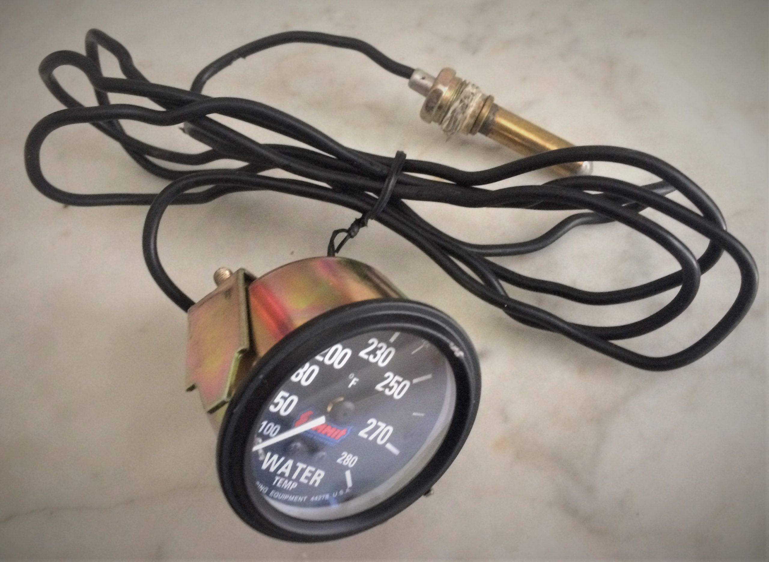
Look at the back of a mechanical temperature gauge and you’ll likely see a sealed tube permanently attached to the back of it. That tube contains a gas/fluid that expands and contracts as the temperature inside the tube changes. The tube connects to the gauge and, on the other end, it terminates in a threaded probe that installs into your engine’s water jacket or other cooling passage.
As the engine heats up and cools down, the gas reacts, then the gauge’s internal mechanism interprets the changes in pressure to deliver a temperature reading.
Pros & Cons of a Mechanical Coolant Temperature Gauge

There’s one main advantage to a mechanical gauge—it requires no electricity (save for an optional backlight so you can see it at night). That means you don’t have to worry about matching the gauge to its correct sending unit either.
And since it doesn’t rely on electricity, it’ll still deliver an accurate reading after the ignition key is removed, which can be handy if you want to see how heat dissipates when the engine isn’t running.
A mechanical temperature gauge can be pretty easy to install too, just thread the probe though the inside, then out to the engine bay, and screw it into a coolant port.
But at the same time, installation can also be a big drawback for a mechanical temperature gauge. The capillary tube needs to be routed through the engine and dash carefully, avoiding any sharp bends or kinks. If the tube breaks or gets ruptured, it’s often easier to just buy a new gauge instead of repairing the old one.

You’ll also want to keep the tube away from other heat sources, like blazing-hot header tubes, as ambient heat can affect the gauge reading. The tube’s got a set length too, so if it’s not long enough to reach the gauge and where you want to install the probe, then you’ll have to find a new gauge or a different spot to put the probe.
How Does an Electrical Water Temperature Gauge Work?

An electrical water temperature gauge essentially consists of two main parts: the gauge and a sending unit, with a wire to connect them together. For the specific sending unit pictured above, you thread the sending unit into the engine’s water jacket or other coolant passage, then you connect the top terminal via a hookup wire to the gauge in the cabin.
Inside the sending unit is a thermally-sensitive electrical resistor, or “thermistor” if you’re in a hurry. Basically, as the temperature around the sending unit fluctuates, the electrical resistance of the thermistor changes too. The gauge interprets the changing resistance values to deliver a temperature reading.
Pros & Cons of an Electrical Coolant Temperature Gauge

The primary advantage of an electrical coolant temperature gauge addresses the main drawback of the mechanical gauge’s capillary tube: Since it uses an electrical signal, you can route the wire dang-near any way you want it—around sharp corners, through tight places, and near other heat sources. (OEMs like electrical gauges because it makes designing a car much easier.)
But there are a few drawbacks to consider too. Since the gauge relies on resistance, you’ve got to ensure your electrical connections are clean and sound. Corrosion, buildup, and loose wires can affect the gauge readings, and it may be so subtle that you won’t notice it’s happening.
The sending units often use a chassis/engine ground too, which means if you’ve got grounding/continuity issues between your engine and the gauge, you’ll likely get erratic readings.
You’ve also got to make sure you’ve got the correct sending unit for your gauge—they’re not always interchangeable and a mismatch can cause inaccurate readings or prevent the gauge from working at all.
How to Test a Mechanical Coolant Temperature Gauge

Testing a mechanical temperature gauge is a pretty easy job, provided you’ve got the gauge out of the vehicle already. You simply set the gauge’s temperature probe in a pot filled with water on your stove, then set the gauge and the rest of the capillary tube away from the heat.

Turn on the heat and your gauge’s needle should move as the water temp. begins to rise. When the needle hits about 212 degrees F, the water should be boiling. Or, if you want a more precise test, put another thermometer in the water, one you trust, and then compare readings as the water temps. change.
Any discrepancy (or failure to read altogether) likely indicates a bad gauge.

How to Test an Electrical Coolant Temperature Sending Unit
Testing an electrical water temperature gauge sending unit is a bit more tricky, but if you’ve already got some electrical know-how, then this’ll be pretty straightforward.
NOTE: For the purposes of this article, we’re only testing the sending unit and, even then, we’re doing it arbitrarily—you’ll see what we mean in a sec.
As alluded to above, sending units can differ with the gauge manufacturer, so it’s difficult to pin a specific resistance reading to a specific temperature. To that end, we’ll simply show you how to take resistance readings and you can compare your data with the gauge manufacturer’s information.
You may be able find someone online that’s already done the resistance/temperature comparison spec work for you too.

To do this test, you’ll need a good multimeter set to take resistance readings (in ohms). It’ll also be a smart idea to have an additional thermometer handy, as it can help you log your resistance readings at specific temperature points so you can compare them with the manufacturer’s specs.
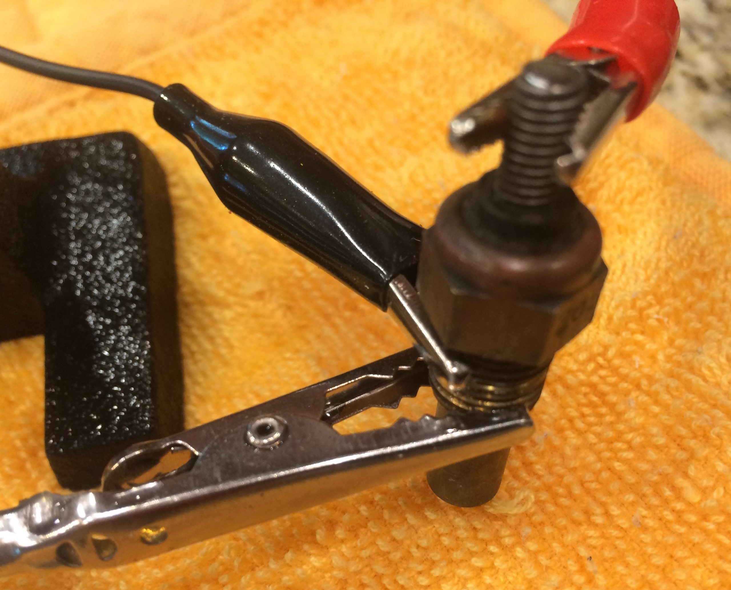
Clip a set of test leads to the sending unit like shown in the picture above (or to its individual terminals, depending on your sending unit design). Make sure they don’t touch or enter the water. Then clip your leads to your multimeter probes, secure the sending unit in a jig (we used one of those “helping hands” parts holders), and plunk the jig into your pot of water on a stove.

Just like before, turn up the heat and you should see resistance drop as the water temps. rise. Again, unless you know what your manufacturer specs out for your specific gauge (like 30 ohms = 200 degrees F), these numbers won’t help much. If you do, start making a chart on a notepad that lists the temperature and its related resistance readings.
Even if you don’t know the manufacturer’s specs, at the very least, this test can show you that the resistance readings are fluctuating and there hasn’t been a complete electrical failure of the thermistor inside the sending unit.
And this also highlights the importance of making sure you’ve got the correct sending unit for the electrical gauge you’re using.
What’s Better—A Mechanical or Electrical Coolant Temperature Gauge?
The honest answer is, it depends. Both designs have proven accurate and reliable, provided they’re in good working condition. If your space allows for a mechanical gauge, then that might make for an easier install, yet if you’re interior is cramped, an electrical gauge may be your only option.
Or as the meme says, why not both?

In the case of our Jeep CJ, we were able to keep its stock electrical gauge hooked up and simply added a supplemental gauge in a separate gauge panel for some redundancy and peace of mind. For its particular 258 inline six engine, we simply retrofitted a later style 4.0L water neck that had an additional port for our mechanical gauge, while the stock sending unit threads in at the back of the cylinder head, like normal.
You may be able to add a similar setup too, by tapping a hole somewhere for the extra probe (if you’re mechanically inclined), or an easier route may be to install a sender fitting adapter inline with your radiator hose.
Thanks, Paul, I bookmarked this great article.
Or on older cars, the wire resistance, connector or ground resistance might have changed. But yet it seems to work. Been there.