Even though it’s a GM LS world, the Gen 1 small block Chevy remains a popular choice for many builders. We’re going to show you how to build a 422 cubic inch stroker small block that makes 700-plus horsepower that even an LS guy will respect. Even better, the majority of the parts are off-the-shelf items. Here are the major components:
- Dart SHP Pro iron block
- Scat/Icon rotating assembly
- COMP Cams roller camshaft
- Trick Flow 18 degree cylinder heads with Jesel roller rocker arms
- Dart single plane intake manifold with an 850 CFM Holley carburetor
- MSD crank trigger, Pro Billet distributor, and ignition wires
In Part One, we’ll go into block prep, the rotating assembly, and installing the camshaft and belt drive.
You can skip ahead to Part 2 here: 422 Cubes of Small Block Thunder, Part 2: Oiling System, Valvetrain & Induction
Block Prep
Our Trick Flow cylinder heads require a minimum bore size of 4.155 inches to maintain adequate valve-to-block deck clearance, so we opted for the Dart SHP Pro block with a 4.165 inch bore. Block machining was performed by Scott Gressman of Gressman Powersports. The Dart block comes with 9.027 inch deck height; Scott milled them to a finished height of 9.001 inches to achieve zero deck with the pistons at TDC.
The cylinder bores were CNC-milled with a carbide cutter to an initial 4.160 inches. The tops of the bores were lightly chamfered to eliminate sharp edges for easier piston and ring installation. The bores were then honed to 4.1642 inches to allow piston-to-wall clearance of 0.0055 inch with torque plates installed. Four light passes with 500-grit stones and plateau honing brushes created a uniform cylinder wall finish, minimizing microscopic peaks and valleys for superior oil retention and faster piston ring seating.
The Dart block’s lifter bores measured 0.9040 inch. Our .9038 inch solid roller lifters require 0.0015 to 0.0018 inch of oil clearance, so Scott milled the bores to .9054 inch to achieve oil clearance of 0.0016 inch.
I checked all threaded holes to verify they were tapped deep enough. One hole at the front had to be tapped an extra two threads to allow the threaded plug to seat and avoid contacting the timing cover. I also carefully deburred the bottom edges of the cylinder bores to eliminate sharp edges. This helps avoid scratching the piston skirts and eliminates potential stress riser areas.
The block was initially cleaned in a jet wash, followed by a very hot water and Dawn dishwashing liquid bath. All oil passages, lifter bores, and cylinder bores were washed using appropriately sized brushes followed by repeated rinsing and blowing with compressed air. Once dry, exposed machine surfaces were lightly coated with WD-40 to prevent surface oxidation. All machined surfaces were carefully masked and the block was painted with SEM self-etching primer and red industrial enamel paint.
Checking Crankshaft & Connecting Rod Clearance
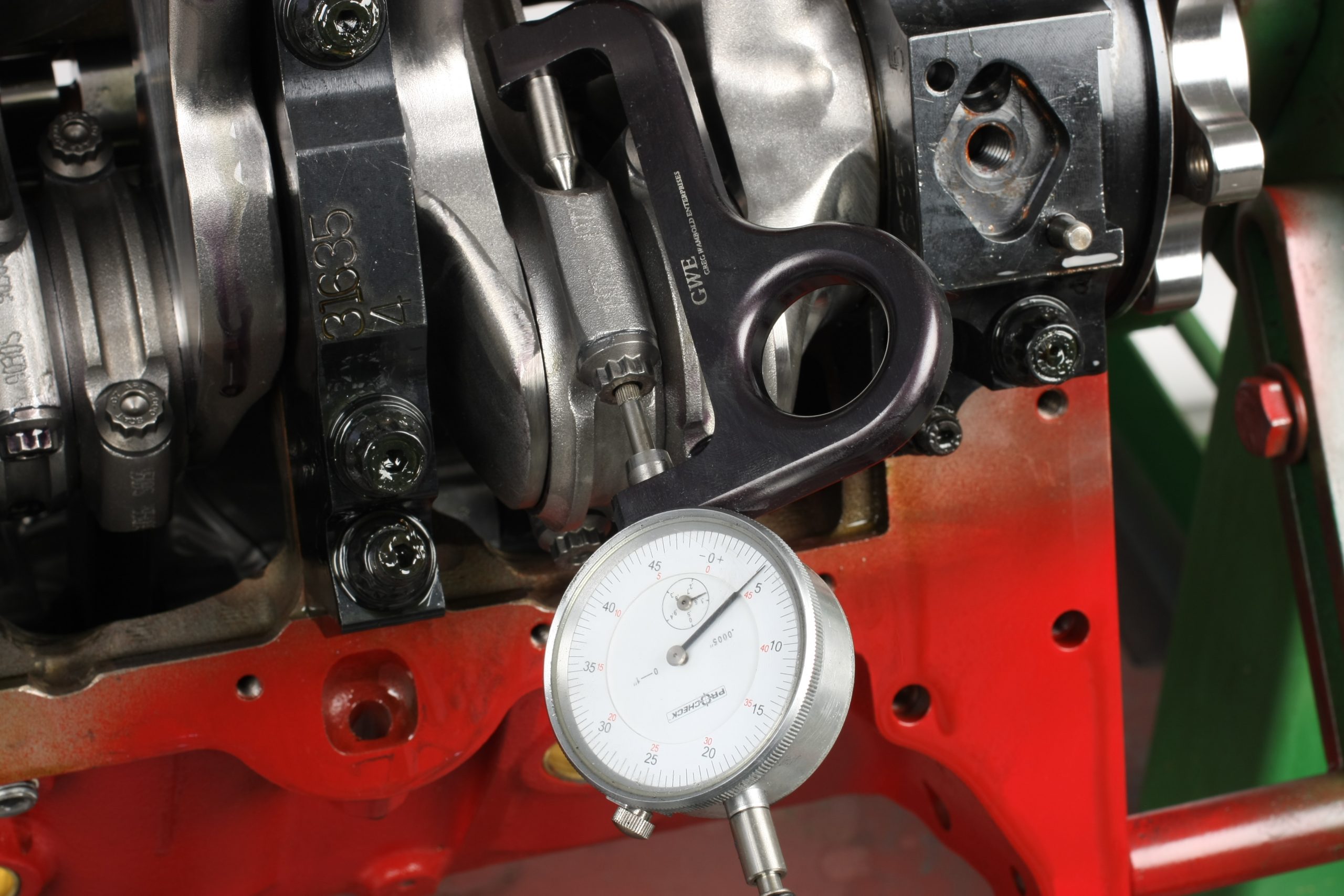
With upper main bearings installed and lightly oiled, the Scat crankshaft was installed and rotated to verify we had no counterweight-to-block clearance issues. Our tightest clearance was a healthy 0.100 inch. The crank was also checked for endplay; ours measured 0.006 inch. Generally speaking, acceptable endplay should be in the 0.004 to 0.008 inch range.
A piston and rod combo was temporarily assembled and installed in one cylinder at a time to check rod big end clearance at the pan rail and upper web areas. We found light contact on the outboard side of each cylinder due to the 3.875 inch crank stroke. The tight spots were relieved using a pneumatic die grinder and a milling bit. Clearance was verified at 0.080 to 0.100 inch.
Balancing the Rotating Assembly
The rotating assembly was balanced at Medina Mountain Motors. Owner Jody Holtrey weighed all components to establish the correct bobweights. In the old days when OEM parts were used, it was standard practice to find the lightest connecting rod and piston to establish a baseline, then grind material from the remaining parts to weight-match the entire set. Today’s aftermarket rods and pistons are so closely weight-matched that little or no correction is necessary. Our Scat H-beam rods had a tolerance range of a mere 0.7 grams, and our Icon pistons had a range of only 0.2 grams. Keep in mind that 1 gram is equal to the weight of a single U.S. currency bill. While no machining was needed, we did mate lighter pistons to the heaver rods, resulting in a close-to-zero tolerance for the set.
With our lightweight pistons and the weight-relieved Scat crank, Jody had to insert a 28 gram slug of tungsten into the front counterweight and a 20 gram slug in the rear. Our final crank balance result was -0.9 grams front and -0.5 grams rear, which is within the ideal range.
Camshaft Installation
Here are specs for our COMP Cams solid roller camshaft:
- Duration @ 0.050″: 263° intake/272° exhaust
- Gross valve lift with 1.5:1 rockers: 0.648″ intake/0.645″ exhaust
- Gross valve lift with 1.6:1 rockers: 0.691″ intake/0.688″ exhaust
- Intake centerline: 108°
- Lobe separation: 108°
It’s important to note that our Dart SHP Pro iron block features a big block Chevy cam bore (2.120 inch). The correct cam bearings are provided with the block. These bearings have an anti-friction coating, three oil holes, and a continuous oil groove on the outside diameter. When installing the bearings, make sure that one of the oil holes aligns with the oil feed holes at the upper main saddles. With the bearings installed, the cam was installed to verify fit. We then removed the cam, coated the journals and lobes with Royal Purple Max Tuff assembly lube, and reinstalled it for good.
Rod & Main Bearing Clearance
Using Plastigage to measure bearings may be convenient, but it’s not the most accurate method. We used calibrated micrometers and a bore gauge to determine oil clearances. Oil clearance for both the main and rod bearings was 0.0025 inch. For the rods, I ended up using a standard upper bearing shell and an “X” lower bearing shell to achieve the required clearance. If I had used X bearings all-around, I would have gained an additional 0.001 inch of oil clearance.
Crankshaft Installation
We installed the crankshaft, main bearings, and main caps, then rechecked crank thrust using a dial indicator. Thrust was 0.006 inch and the crankshaft was easily rotated with one hand. If the crank resists turning by hand, carefully recheck to make sure the main caps are in their correct positions and orientation.
The main caps and crankshaft were then removed. The bearings were cleaned and reinstalled in the block and caps with Royal Purple Max Tuff assembly lube on all exposed bearing faces, including the thrust shoulders on the number five rear main bearing.
Our Dart block and Scat crank are set up for a two-piece rear main seal. This build features an external vacuum pump which will pull about 15 inches of vacuum in the crankcase. It’s recommended to use a seal that is specifically designed for high vacuum applications—we used a Fel-Pro rear main seal. The upper and lower seal were installed slightly cocked, with the opposing ends protruding out about 1/8 inch. This allows seal-to-seal mating above and below the main cap to block parting line, helping to insure against a potential oil leak. Prior to installing the rear main cap, a small bead of RTV was applied to the block’s inner corners where the main cap seats against the block.
The crankshaft was carefully placed in the block and the main caps installed. The Dart SHP Pro block is set up for main cap studs. The studs are installed in the block finger-tight and the washers, fine threads, and nut undersides are lubed. Never torque studs into the block; clamping load is achieved as the nuts are tightened. The 7/16 inch main cap fasteners were torqued to 65 ft.-lb. and the 3/8-inch outboard fasteners on number 1 and 5 caps were torqued to 35 ft.-lb. Once the main caps were fully torqued, we checked crankshaft endplay again to verify it was still at 0.006 inch.
Piston & Rod Installation
The rings supplied with our Icon pistons are file-fit with an end gap specification of 0.0187 inch. I used a Summit Racing ring filer to gap the top and secondary rings to 0.019 inch. The filed edges were carefully deburred using a small fine flat file. When filing, don’t get carried away and remove too much material. It’s better to creep up on the desired gap.
The cylinder walls were cleaned with a fast-drying solvent and a lint-free towel, then lubricated with engine assembly lube. Avoid using a synthetic lube on the cylinder walls as it can prevent the piston rings from properly seating during engine break-in. We also applied assembly lube to the ring grooves and rings to provide enough lubrication without making an oily mess during piston installation.
Since our Icon pistons feature a fairly short CD (compression distance), the oil ring groove intersects the wrist pin bore. A support ring is installed at the base of the oil ring groove to provide a stable floor for the oil ring package. The rings have a small male dot that must face down and be positioned directly above one of the pin bores. This dot prevents the support ring from rotating and its end gap from moving into the pin bore area. We installed the rest of the ring package; all end gaps must be clocked 180 degrees from each other to keep them from aligning and allowing oil to get past the rings and into the combustion chambers.
Our Scat rods came with ARP 2000 rod bolts. The specification sheet has specs for two methods of tightening—recommended torque value and maximum allowable bolt stretch. Scat recommends a torque value of 70 ft.-lb., and stretch is not to exceed 0.005 inch. Regardless of method you use, apply quality engine lube to bolt threads and to the underside of the bolt head to reduce friction and prevent galling.
Jesel Belt Drive
With the camshaft and rotating assembly installed, we turned our attention to the Jesel belt drive system. A belt drive offers increased cam timing accuracy and keeps ignition timing stable by minimizing the transfer of crankshaft harmonics to the cam and valvetrain. The Jesel system features a machined aluminum base cover that seals against the block, allowing the belt and sprockets to run exposed. Cam timing adjustments are performed by loosening the four nuts on the spider gear. Turn the crankshaft clockwise to retard the camshaft or counterclockwise to advance. Each mark on the spider gear equals two degrees at the crankshaft.
The mounting plate should be test-fitted to verify it mates flush with the block. During our build, two of the 3/8 inch NPT plugs at the front of the block protruded a bit and hit the plate. I shaved the plug faces down 0.040-inch on a lathe to gain the needed clearance. The mounting plate is secured to the block using an OEM-type gasket, a thin layer of RTV, and ten 1/4-20 socket head cap screws included with the kit. An alternative is to install ARP studs, P/N ARP-334-1401. They have guides for mounting plate positioning that makes installation easier.
The Jesel drive comes with three camshaft thrust shims. With all three installed, we checked camshaft endplay with a dial indicator that contacts the face of the camshaft adapter. You want to prevent the camshaft from thrusting front-to-rear to prevent the lifter rollers from side loading on their roller bearings. With our roller camshaft, we wanted endplay between 0.006 and 0.012-inch. I ended up using the 0.015 and 0.020 inch-thick shims to get 0.006 inch of endplay.
Harmonic Balancer Installation
I chose a Fluidampr 6.25 inch balancer. The crank snout has a 1.2465 inch O.D. and our Fluidampr bore measured 1.2445 inch, providing us with a very nice 0.002 inch press fit. Always measure as it’s possible that the crank snout and/or balancer bore may cause fitment issues, and you don’t want to resort to the Big Hammer to beat the balancer on the crank.
Next Up
In Part Two, we’ll degree the camshaft and install the Moroso oil pump and oil pan, the Trick Flow Ultra 18 250 aluminum cylinder heads and valvetrain, and Dart single plane intake manifold and Holley Ultra XP 850 CFM carburetor. It’s gonna be great!


[…] 422 Cubes of Small Block Thunder: Building a 700+ Horsepower Small Block Chevy (Part 1) – Even though it’s a GM LS world, the Gen 1 small block Chevy remains a popular choice for many builders. We’re going to show. […]
Where’s the rest of the story? What Dyno numbers did it bring?
Hey Jeff, check out Part III here:
422 Cubes of Small Block Thunder Part 3: Ignition, Accessories & Dyno Results
Would this be a good motor I can run nos on?
No the ring pack is too close to the crown. Also the pin height is very high and would not be there get choice for any type of forced induction aka nitrous use.