The world of high performance engines can be a very confusing place, where terms and specifications seem to be full of obscure references that appear to make no sense. But just like learning a new language, if you break each one down into smaller pieces, everything becomes easier to understand.
***
Story Summary Overview:
- A “Cam Card” or “Timing Card” is a document included with a new camshaft that contains its key specs
- You’ll find details on important cam characteristics like Lobe Lift, LSA, Duration, and Advance
- Knowing these specs is critical to understanding how the engine will perform with the camshaft installed
- You can use cam card specs to select the best camshaft for your particular engine
- This article highlights the key cam specs you’ll find on a cam card & explains how to interpret them
***
What is a Camshaft Timing Card or Cam Card?
One area of confusion is certainly a camshaft timing card. All aftermarket and production camshafts use a series of terms and specifications to identify their operating characteristics. These may seem obscure and even perhaps baffling, but in fact these cam specifications lay out a simple way of determining exactly how a particular camshaft will operate in the engine. That’s vitally important when it comes to choosing the right camshaft.
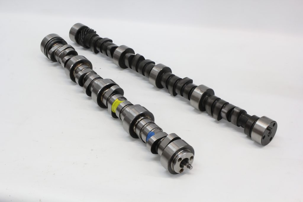
The camshaft has been described as the “brain of an engine,” so let’s break down each of these specs to decipher how a cam exerts its control over an engine.
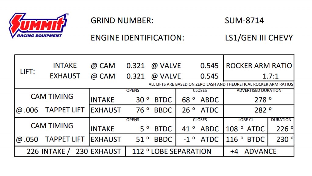
We’ll use a timing card from one of Summit Racing’s Pro LS series camshafts as our example, but these same numbers and relationships will apply to any camshaft from any manufacturer for any four-stroke engine.
What Does a Camshaft Do?
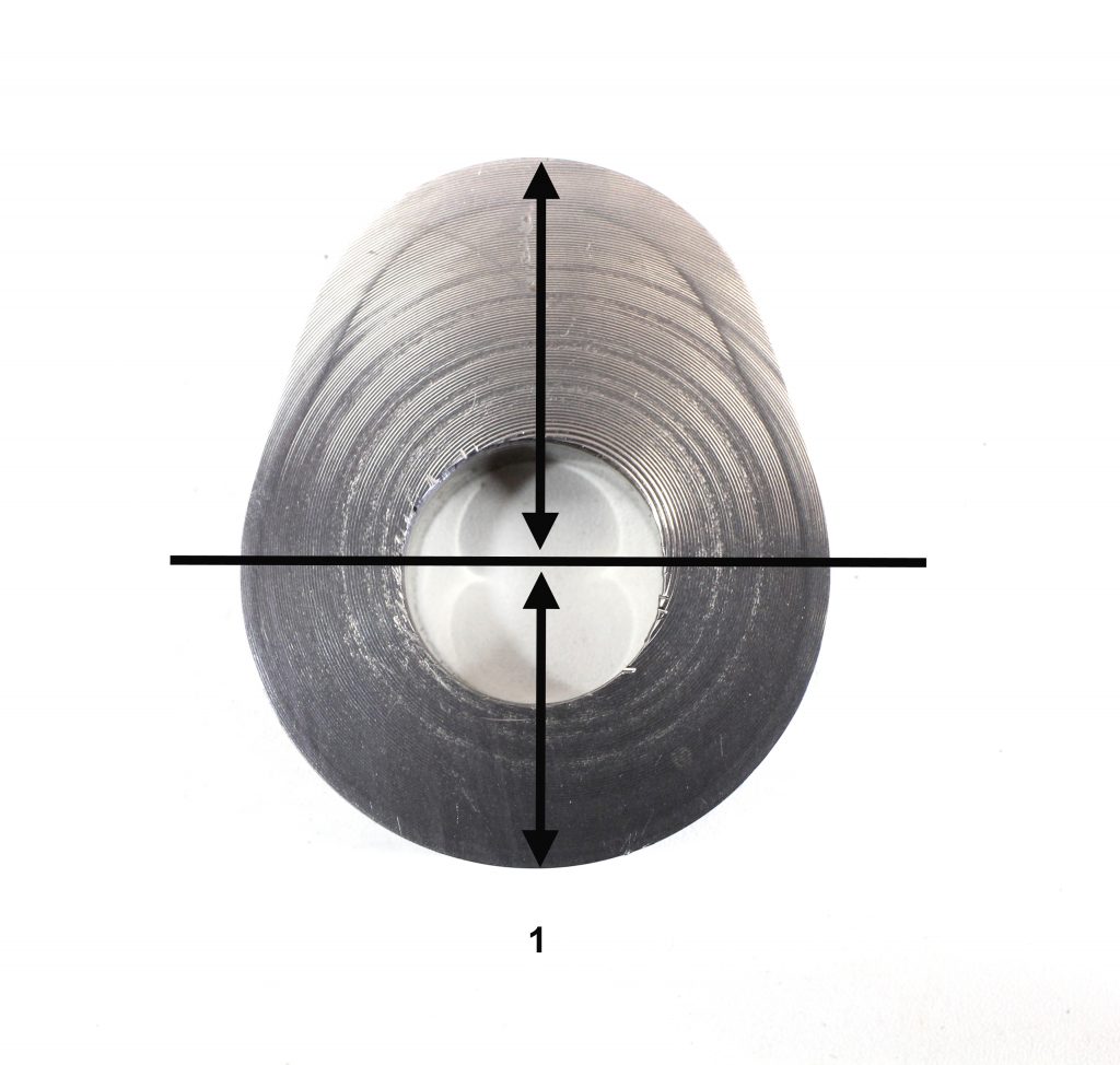
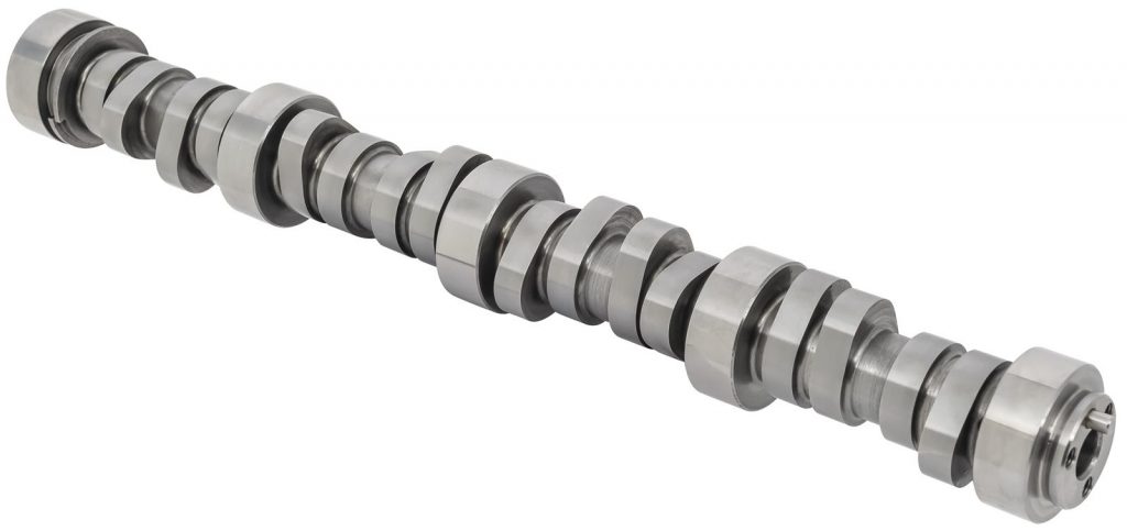
Let’s begin by describing exactly what a camshaft does. A camshaft is really a device used to convert rotating motion into linear (up and down) movement. This is accomplished by use of a cam follower or lifter that starts on the round portion of the eccentric, which is called the base circle. As the cam lobe turns and the lifter follows the rise of the eccentric, the lifter moves upward, converting this rotating motion into an upward movement connected by the pushrod to the rocker arm.
Summit Racing’s got a handy camshaft timing calculator that can help you determine the right cam specs for your performance needs.
Reading a Cam Card: Lobe Lift
This simple upward movement of the cam lobe can be measured in terms of inches (or millimeters) of lobe lift. On our sample Summit Racing Pro LS cam card above, the first line is called Lift and is detailed as either intake or exhaust lobe lift at the camshaft. Note that in this particular case, both the intake and exhaust lobes generate a lobe lift of exactly the same amount: 0.321-inch. You will often see where the lift will be different for the intake versus exhaust.
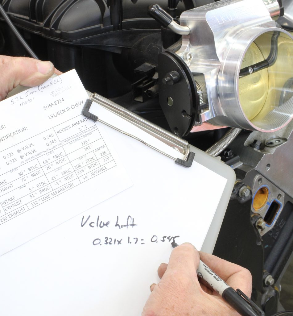
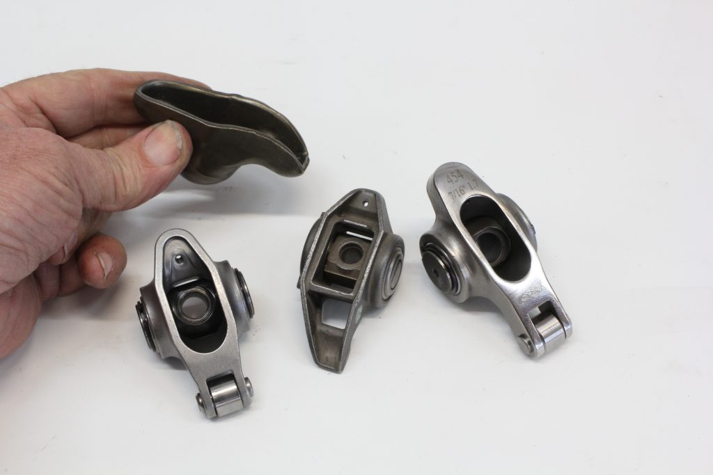
Reading a Cam Card: Rocker Arm Ratio (Rocker Ratio)
On that same line in this cam card, the lift at the valve has increased from 0.321-inch at the lobe, to 0.545-inch at the valve. This is accomplished through the rocker ratio. Note that the card calls this ratio out at 1.7:1. If we multiply 0.321 x 1.7 = 0.545-inch. That’s the lift the engine will see at the valves.
Reading a Cam Card: Duration & Advertised Duration
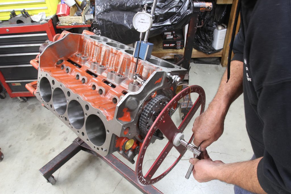
The next spec we’ll deal with is duration. This is defined as the number of degrees of crankshaft rotation that each valve that spends off the seat. All camshaft specs are expressed in degrees of crankshaft rotation. Crankshaft degrees are used because that’s the easiest way to measure these points on the actual engine. Keep in mind that the camshaft turns at half engine speed because the cam drive gear is twice as large as the crankshaft gear. That means the crankshaft has to spin twice for the cam to turn one revolution. That orientation is designed into all four-stroke engines.
You will see that this Summit Racing cam offers duration in two different tappet lift specs of 0.006-inch and also at 0.050-inch. In the early days of camshaft design, the manufacturer decided the beginning and ending positions in terms of tappet lift. Some companies use 0.004-inch and others use 0.006-inch.
A big issue arose when using those different specs made it difficult to compare duration between various cam companies. In the 1960s, the late Harvey Crane called out 0.050-inch of tappet lift as a universal standard which quickly was adopted by all aftermarket cam companies.
The 0.004- or 0.006-inch spec is now called advertised duration. In the Summit Racing cam example, this is the amount of crankshaft rotation that begins once the lifter is 0.006-inch off the base circle and continues until the lifter is 0.006-inch off the bases circle on the closing side. The next two columns on the 0.006-inch duration specs indicate an intake lobe opening point of 30 degrees Before Top Dead Center (BTDC) and 68 degrees After Bottom Dead Center (ABDC).
This means that the intake lobe opens 30 degrees before the piston reaches the top of its stroke. Given there is 180 degrees between Top Dead Center (TDC) and Bottom Dead Center (BDC), then the crank will turn another 68 degrees before the intake valve reaches 0.006-inch off the base circle of the lobe. If we add these three figures together: 30 + 180 + 68 = 278 degrees. This is the total number of crankshaft degrees that the intake valve is open.
We can perform the same math for the exhaust side except that the exhaust valve opens 76 degrees Before Bottom Dead Center (BBDC), turns 180 degrees between BBDC and TDC, and the closes at 26 degrees After Top Dead Center (ATDC). Crunching the numbers gives us: 76 + 180 + 26 = 282 degrees of advertised duration.
Reading a Cam Card: Duration at 0.050″ Lift
The next line offers this cam’s specs at the industry standard of 0.050-inch of tappet lift. Since the crankshaft will turn fewer degrees between the 0.050-inch lift point on both the opening and closing sides, the duration specs will be smaller in degrees than the advertised specs. This is reinforced in the actual specs on the intake side opening at 5 degrees BTDC and closing 41 degrees ABDC. The duration changes to 226 degrees on the intake and 230 degrees on the exhaust side.
On shorter duration camshafts like this particular cam, an interesting event occurs that is worth describing. Note that the closing side of the exhaust spec at 0.050-inch tappet lift is expressed as a negative one (-1) degrees. This means that the measuring point normally expressed in degrees ATDC is really closed Before TDC. To eliminate confusion, the spec is written as -1 degrees. This makes the math simple as 51 + 180 + (-1) = 230 degrees as listed on the card’s right column under the Duration heading.
Reading a Cam Card: Lobe Center Line (Lobe CL)
The column just before Duration on this Summit Racing camshaft card is something called Lobe CL or Lobe Center Line. These are the center lines of the intake and exhaust lobes expressed in crankshaft degrees. The intake center line occurs 108 degrees After TDC while the exhaust center line is positioned at 116 degrees Before TDC. The intake center line is often used as a primary point for degreeing the camshaft.
Reading a Cam Card: Lobe Separation Angle (LSA)
Another important camshaft spec is something called the Lobe Separation Angle (LSA). This is the number of crankshaft degrees of separation between the intake and exhaust lobe center lines. On this cam card, you will see the LSA is 112 degrees. This figure is derived by adding the intake center line plus the exhaust center line and dividing by two. In this case: 108 + 116 = 224 degrees / 2 = 112 degrees.
Reading a Cam Card: Advance
This brings up an interesting point that will also help when selecting a camshaft. Note in the lower right hand corner of the cam card that Summit Racing specs this cam as +4 Advance. What this means is that when this camshaft was machined, the specs called for advancing the intake lobe four degrees. This is often performed on street camshafts as a way to enhance low-speed performance.
All of this is worth noting since it’s best to know that the cam grinder has already advanced the camshaft for you, so there’s no need for additional advance. Let’s look at how this occurs. If the intake center line and the lobe separation angle are the same value, then the cam will not have been ground advanced. So in this case, if the intake centerline was 112 degrees and the LSA was also 112 degrees, then the cam will not have been ground advanced. To make the math work, this would also mean that the exhaust lobe center line would also have to be 112. That would make it 112 + 112 = 224 / 2 = 112 degrees.
As another example, if the LSA was 114 degrees and the intake centerline was 110 degrees, that would mean that the cam was ground 4 degrees advanced and the exhaust lobe center line would then be 118 degrees: (110 + 118 = 228 / 2 = 114 degrees LSA).
Reading a Cam Card: Mechanical Valve Lash
One spec not covered on this cam card relates to a spec called mechanical valve lash. This is the clearance between the rocker arm and the valve tip as measured by a set of feeler gauges when the engine is at full operating temperature. Mechanical lash must be measured when the cam lobe is on the base circle.
***
We’ve moved pretty quickly through this cam card so you may want to review what we’ve established until the numbers make sense. Once you are comfortable with the numbers and how they relate to engine performance, you’ll find every cam card a source of a significant amount of useful information.
[…] The world of high performance engines can be a very confusing place, where terms and specifications seem to be full of obscure references that appear to make no sense. But […] Read full article at http://www.onallcylinders.com […]
Well done..Jeff…
Thanks.. Chris…
You are correct sir! I should have included that bit of information in my answer. Good job
Jeff
Great article. With regards to degreeing a cam at installation time, is it unusual to have to use an ‘adjustable’ timing set in order to get the cam degreed where the cam manufacturer recommends? On my last two cams, setting the timing set “straight up” didn’t work for either one. The manufacturers in both cases (Comp and Bullet) specified installing them at 106 ICL, but to get there both times I had to use an adjustable timing set to get them to 106.
Rob,
It is not unusual to have to move the cam a couple of degrees or so. It might depend on how far you had to move the cam. A couple of degrees is not a big deal. But if it was more, I suspect that your established TDC might not have been accurate. My experience is that the cam’s rarely need to be moved from their standard location. I would not be concerned if it was only a couple of degrees of change.
Maybe I’m weird but I LOVE reading cam cards when building an engine. I’m SERIOUSLY looking forward to reading the card for the Edelbrock Rollin Thunder retrofit roller cam that I ordered for the 408 sbc that I’m working on now!
I liked the articulate but it really only explained the cam card specks. Duh! That was the title of the article! Now how about going one step further and explain how the changing of compression, duration, lift and LSA effects the change of an engine. Where is Smokey when you need him?
Hey John, thanks for reading. We dove into what some of those specs mean with a bit more detail in an earlier article. Click here to check it out.
Great article! Sure glad I came across it. Until now I totally misunderstood the difference’s of “advertised lift & duration numbers -v-.050 numbers. Every bit of the info in this article is highly useful to me
i for sure could not under stand how .05 of lift equated to a -1 . can anyone explain the math when we are doing the LSA
What is the most common error of installing a camshaft incorrectly? Are the manufacturer’s installation directions sufficient?
Most common error is finding TDC on the engine. And no, the manufacturer’s directions are usually not sufficient..
Vey good point Ray–and Jeff did a deep dive into that topic too, check it out.
…
TDC: An Important Tuning Position That Should Not be Overlooked
I enjoy your articals in my past 50 plus years of machine & building engines it is nice to see articles by you teaching a lot of people the right message about camshafts in there proper use for each engine combination. Thanks for all you do for us great writing.
Thanks Lorry Azevedo, HAT Racing Enterprise.
hi jeff smith,
I have a Melling cam shaft #ccs20. for a 402cu in bored out .030
“It shows from Melling specs. intake “-14 btc opens.” what is -14? // “30 ABC. closes”. @.050 duration 196 / advert. 270
from their chart” exh. – ” 33 BBC opens.” // ” – 17 atc closes”. what is -17? @ .050 duration 196 / advert. durat. 270 int.
you explained it perfectly in your article. btdc , atdc , bbdc , abdc ,
center line is, int. 107 = lobe sep. at 113
exh 119 =
please explain bbc btc abc atc, and the minus. –
I know every manufactures’. explains it differently.
are the specs, right?
thankyou
Jim
Take note:
BBDC = BEFORE BOTTOM DEAD CENTER
ATDC = AFTER TOP DEAD CENTER
etc …
Now if it’s -1 BTDC
It just means 1° ATDC
Basically what 9th grade Algebra was suppose to teach us…. I also played hookie the day they taught that in school ..
Hi Jeff
Thanks for your informative article.
My understanding is that all cam specs are expressed in crankshaft degrees, except for Lobe Separation Angle, which is expressed in camshaft degrees. In the example above, ‘LSA = 108 + 116 = 224 degrees / 2 = 112 degrees’. The divide by 2 is the conversion from crank to cam degrees.
Let me know if I have it wrong.