Everyone knows the classic four-stroke engine cycle: intake, compression, combustion, exhaust. While all four play a part in performance, it’s the combustion step that relies on the critical sequence of idealized ignition timing. Late model EFI engines use complex mapping to implement proper timing; before the days of electronic spark control, distributors performed this task.
This story will reference engines with distributors instead of EFI. We’ll look at three critical ignition timing areas: initial timing, mechanical advance, and vacuum advance. Together, they form the overall spark curve the engine uses over its entire RPM and load range for optimal performance. The important part to remember is that all three work together on a street engine not only to maximize power but also to enhance drivability and mileage.
It’s also important to note that all distributors spin at half of engine speed. In this discussion all the specifications will be given in crankshaft degrees. Some shops that use a distributor machine may report an ignition curve in distributor degrees, which is half of crankshaft degrees. So if you see a spec on a distributor, it’s worth asking if the specs are in crankshaft degrees.
Let’s set some definitions so everyone understands the terms we will be using:
Initial timing (sometimes called base timing) refers to the position of the distributor that creates the crankshaft position where the spark plug fires at idle. This and all other timing specs refer to the position of the piston as it approaches the top of its stroke, called Top Dead Center (TDC). Engines tend to idle best with a small amount of ignition advance to begin the combustion process. Advancemeans the spark plug fires before the piston arrives at TDC, referred to as the number of degrees Before TDC (BTDC).
A popular misconception is that when the spark jumps the gap on the plug, there is an instant explosion inside the combustion space. This is not entirely accurate. When the spark occurs, the combustion process requires a short amount of time to create the flame front that builds pressure. Conventional wisdom holds that lighting the fire a few degrees BTDC even at idle allows the combustion process adequate time to create maximum cylinder pressure just as the piston and rod assembly apply maximum leverage on the crankshaft. This occurs roughly at around 15 to 17 degrees After TDC (ATDC). Engines run best with initial timing that fires the spark plug somewhere between 4 and 12-14 degrees BTDC. At peak power at high RPM, total timing numbers generally are 32 to 38 degrees BTDC. This additional timing is especially important because as engine speed increases, there is less time for combustion to occur.
Mechanical, or centrifugal advance in a distributor is controlled by a simple, weighted device similar to the speed governor weights and springs on an old steam engine. The weights pivot outward as shaft speed increases. The rate of change for these weights is controlled by the springs. The total amount of advance is generally controlled by a pin that travels in a slot in the distributor advance mechanism. The longer the slot, the more advance is created.
This centrifugal mechanism is on the same shaft as the trigger wheel that, on a V8, will have 8 poles. As the advance weights move outward with RPM, the shaft moves the trigger wheel forward, advancing the spark. Mechanical advance systems generally add between 20 and 30 degrees of timing. Adding the mechanical and initial values together generates the total timing. As an example, 10 degrees of initial and 24 degrees of mechanical advance creates 34 degrees BTDC of total timing.
Vacuum advance is a separate system that uses a small diaphragm assembly attached to the side of the distributor. Not all distributors are equipped with vacuum advance, but for a street engine it can be very useful. Engines operating at part throttle require more ignition timing to light the fire in the chamber because the cylinder contains only a portion of the total charge that is present at wide-open throttle (WOT). With a reduced density charge in the cylinder, more timing is required in order for the engine to run efficiently.
Intake manifold vacuum is a very easy way to judge engine load. We need to know about vacuum because this is the force that will ‘pull’ on the diaphragm on the vacuum advance canister, which in turn moves the baseplate tied to the magnetic pickup in the distributor to advance the timing. Keep in mind that as engine load increases, vacuum is reduced and vacuum advance will also be reduced.
Part throttle restricts the volume of air into the engine, which creates a vacuum in the intake manifold at a pressure that is much less than atmospheric. Atmospheric pressure can be expressed as pounds per square inch (PSI), millibars, or inches of mercury (inHg). The most familiar atmospheric pressure standard is 14.7 PSI at sea level. This same pressure can also be expressed as 29.92 inHg.
Most automotive engine vacuum gauges are scaled to read inHg. A common automotive vacuum gauge reads 0 (no pressure) when exposed to atmospheric pressure. When the gauge is measuring manifold vacuum on a running engine, it will actually be reading negative pressure. It’s just not expressed as -20 inHg.
Engine manifold vacuum can be as high as 16-18 inHg at idle on a stock engine. As the throttle opens and load on the engine increases, this reading will move closer to 0 inHg on the gauge. These readings are referred to as PSIG or PSI gauge pressure readings. Yes, it’s a little confusing since we referenced 14.7 PSI as atmospheric. It takes a little effort to get comfortable with the science, but as you will see, it’s necessary.
Vacuum advance is completely independent of mechanical advance. We like to describe vacuum advance as load-based timing since timing is added when there is a light load on the engine. Conversely, timing is reduced when load is applied. Mechanical advance is strictly determined by engine RPM and nothing else. When load is applied and manifold vacuum is lower, less timing is added because the cylinders are more densely packed with air and fuel, and require less ignition advance to create maximum power.
At part throttle initial, vacuum, and mechanical advance are all added together. Here is an example: Let’s start with 10 degrees of initial timing at idle. We add 18 degrees of mechanical advance at 2,400 RPM for a total of 28 degrees of advance. Now let’s add 12 degrees of vacuum advance with engine vacuum at 16 inHg. This would create a total ignition advance of 40 degrees of timing at that specific point.
If we add load to the engine by stepping on the throttle in high gear, maintained the same 2,400 RPM (climbing a hill, for example), and engine vacuum dropped to 10 inHg, vacuum advance would be just 4 degrees. Total advance at 2,400 RPM would then be 32 degrees.
Checking these numbers on an engine in the car is relatively easy with a dial-back timing light. We did a story on how to use a dial-back timing light as part of this Basics series that might be helpful to you.
You may have read that race engines don’t use mechanical or vacuum advance since they always run at WOT. This is true in most cases because these engines operate at extremely high engine speeds where fixed ignition timing is all that is necessary. One problem that crops up is starting an engine with 34 degrees of initial timing is very difficult. That’s why many race ignition boxes have a start retard feature to reduce timing to a level the starter can handle.
A very quick timing curve is also not always necessary for a street engine. You may have heard about advance curves that have total advance all in by 2,000 RPM. It’s possible, but the weak springs required to do this start the mechanical advance at or below idle speed. Stabilizing the idle speed low enough to set initial timing becomes difficult because centrifugal advance has already started. It’s a much better plan to start the mechanical advance curve at around 1,300 to 1,400 RPM and have it fully advanced by 3,000 RPM.
It’s also important to mention that in most applications, the vacuum advance canister is connected to what is called ported manifold vacuum. That means there is no vacuum sourced to the canister at curb idle. With ported advance, vacuum is applied once the throttle is opened past curb idle. Some tuners prefer to add vacuum advance at curb idle on engines with big camshafts to improve idle quality. If you choose to do this, be sure to remove the vacuum advance line from the vacuum source before checking initial timing. If the initial timing numbers appear excessive (20 degrees or more), it could be that manifold vacuum is being applied to the advance canister.
There are many more nuances and little tricks of the trade when working with mechanical and vacuum advance distributors, but hopefully we’ve shed a little light on this three-tiered timing arrangement. Tuning will make you a little bit like an orchestra conductor getting all of the instruments to play the same tune at the same time. When that happens, your engine will make some beautiful music!
Most engines use a timing tab, located on the front timing cover, which references advance. In this case, the tab reads in degrees BTDC above the zero mark with the mark set here at 10 degrees BTDC. Image/Jeff Smith
…
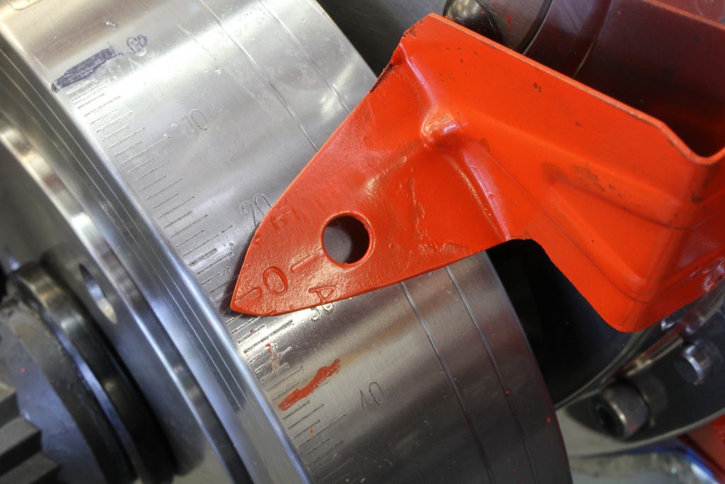
Some performance engines use a degreed balancer. In this case, we’ve trimmed a stock bolt-on tab to a point that references zero degrees. The timing is read from the degreed numbers on the harmonic balancer. In this example, it’s hard to read but the pointer indicates 26 degrees BTDC. Reading total advance with this arrangement does not require a dial-back timing light. Image/Jeff Smith
…
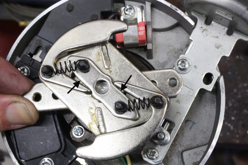
Centrifugal or mechanical advance works based on centrifugal force. As the distributor shaft spins faster the weights pivot outward, which moves the eccentric-shaped shaft in the center (arrows). As the weights move the shaft, this advances the position of the spinning 8-pole piece, advancing the ignition timing. Image/Jeff Smith
…

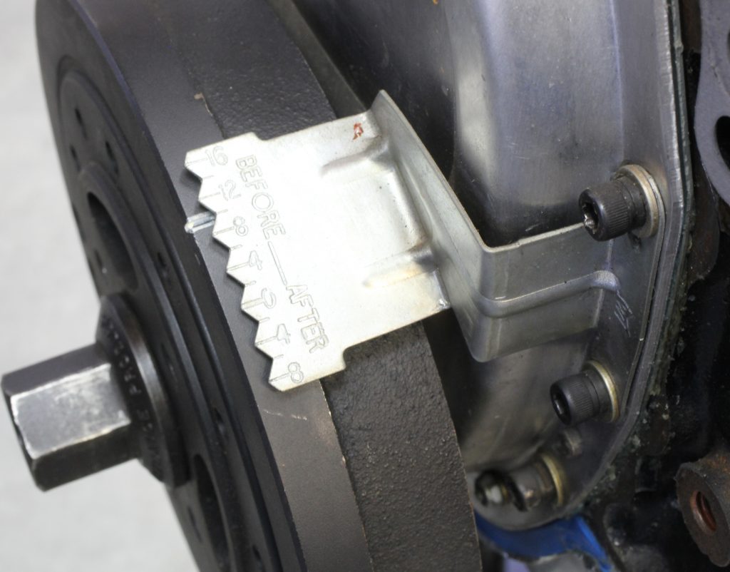
This MSD illustration shows how different size bushings can fit over a pin that rides in the advance slot. Each new MSD distributor is shipped with a selection of different bushing sizes. You can alter timing by changing bushing diameters—use a thinner bushing for more advance, or a larger one for less advance. Factory distributors have a fixed slot length and pin. The slot must be modified to change the amount of advance. Image/Jeff Smith
…
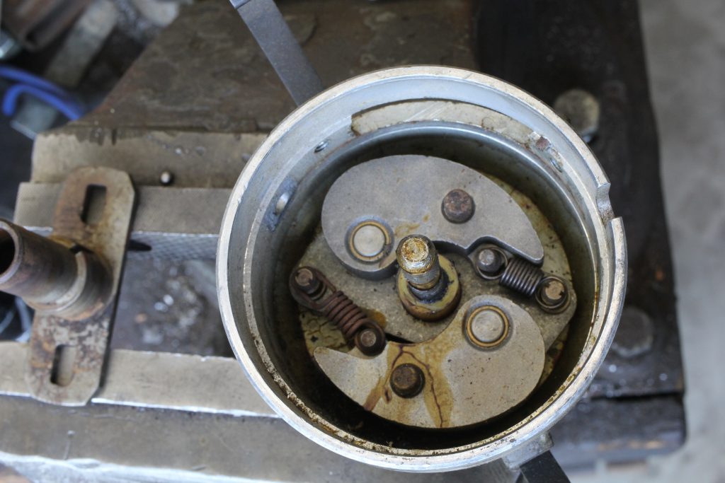
Inside this vacuum advance canister is a small diaphragm that is connected to a link on the advance plate (arrow) that mounts the magnetic pickup in the distributor. As vacuum increases, it pulls on the arm, which rotates the plate and advances the position of the magnetic pickup to add timing. Image/Jeff Smith
…
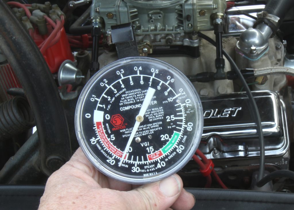
This vacuum gauge reads both manifold vacuum and positive pressure. The scale we’re using for manifold vacuum is the inside row expressed in inches of mercury (inHg). The needle points to just below 10 inHg of manifold vacuum. Mild street engines will idle around 12 to 16 inches of manifold vacuum. This engine has a big camshaft and struggles to idle at 900 RPM at 9.5 inHg. Image/Jeff Smith
…
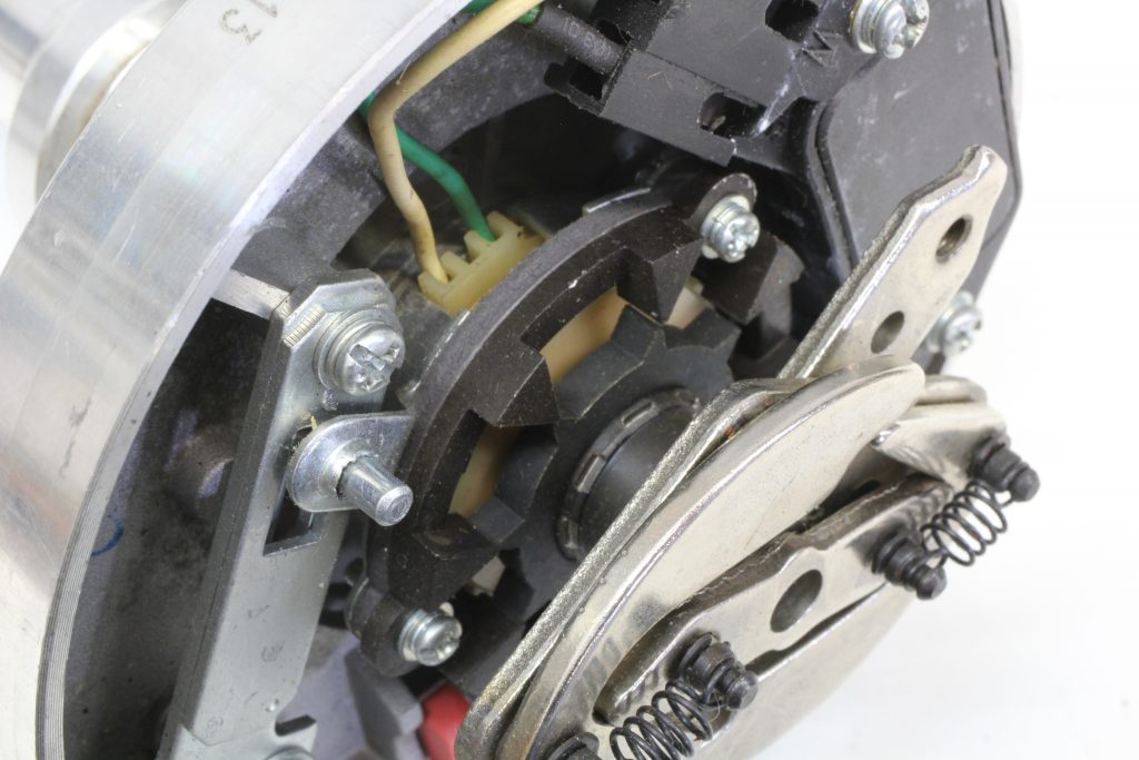
As each of the lugs on the shaft line up with the magnetic pickup, this creates a signal that the distributor uses to trigger the coil and put voltage into the spark plug. Image/Jeff Smith
…
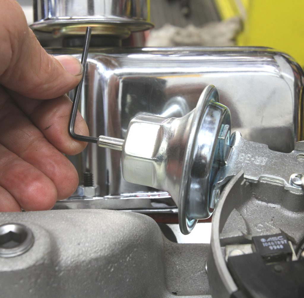
Some vacuum advance canisters can be adjusted by inserting a small Allen wrench into the nose of the canister. Turning the Allen wrench clockwise will increase spring tension working against the vacuum applied to the diaphragm. That will decrease total advance and also slow the rate of advance versus vacuum. Image/Jeff Smith
…
Not all distributors have the mechanical advance weights in a convenient place. Ford and Mopar distributors like this one place the mechanical advance underneath the mount for the ignition pickup, requiring disassembly to access the components. This makes MSD distributors for these engines more desirable as they are much easier to modify. Image/Jeff Smith
…
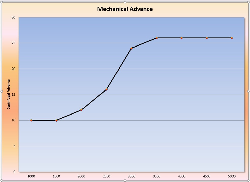
This graph is representative of a typical mechanical advance curve on an engine. Advance begins with timing added after 1,500 RPM and reaches full advance at 3,500 RPM. This curve starts at 10 degrees because this is the amount of initial timing. This curve can be quickened slightly but is a good place to start. Total mechanical advance is determined by the length of the slot in the distributor advance plate while the rate (steepness of the curve) is determined by the weights and springs. Image/Jeff Smith
I’ve recently rebuilt a 1986 318 Mopar. This came to me as a real “Basket Case”,,,, (the person who pulled this apart should of been Shot for claiming of being a Mechanic, a lot of stuff was missing.) I had to basically replace the whole top of the engine….(how do you lose an intake manifold?) I chose to go to Summit Racing for parts, Intake Manifold,Carburetor.
When it came to the Distributor I was in a jam. This model B250 Dodge Van had the infamous “Black Box” Ignition control system on it. I was thumbing through a Jegs catalog and they had a HEI GM type distributor for all makes of Engines for$99.99! I feel that was the best Distributor ever designed, one compact unit… And yes uses stock AC Delco parts.What a god send. Vacuum Advance. The only thing is you have to make your own spark plug wires. Accel 8mm universal comes with both distributor boots, worked out perfect… Runs Fantastic!
[…] Everyone knows the classic four-stroke engine cycle: intake, compression, combustion, exhaust. While all four play a part in performance, it’s the combustion step that relies on the critical sequence of […] Read full article at http://www.onallcylinders.com […]
Not just performance motor that has degree marks on the balancer all sbf whit stock harmanic balancer i seen have the before and after tdc degrees on them
They say that Ford costs so much in maintenance but it has been so smooth and great for us.
Ford is really worth all the money. They may be expensive at some point but the durability is really great!
https://cincinnati-seo.org/
Thanks for sharing this information. I am so glad finding this post as I like mechanical engineering and I encourage my daughter to get admission in mechanical engineering department. But personaly,I like to make reviews, collect information for the people who loves online activities for instance online and earn money.People can play with the first deposit bonuses- you could find more hacks and tips about online casinos.By the way,this post grows inspirations anout mechanical engineering sector.
Very good article
Most speed people don’t have a clue how important a vacuum advance is!!!
[…] timing chain cover. We can use the reference to establish ignition timing as related in a previous Ignition Basics […]
Great article! Thanks!
https://www.onallcylinders.com/
Get a progression ignition Bluetooth to your phone and change the timing to whatever you want without popping the good with the car on or off.also has Killswitch and rev limiter built in. Works great in my car
I’ve got a 426 hemi motor with MSD ignition. The vacuum advance is disconnected, but intact. I’m having a consistent problem with hesitation at sudden full throttle. The initial timing is set at 14°. Good lack of vacuum advance have anything to do with my problem?
Wow, I have been trying to explain exactly what you just said to so many people, so many times, and poof it’s like they can’t comprehend, or retain. But the way you explain it, in sequence like that. Your good. Now I got a 57 to 63 283 .040 over. Forged crank. 3500 stall, Elgin prostock cam BASIC rpm operation 3200 to 6500rpm. Aka 302 cam the way I take it. Matching springs. New valves and keeps and locks. In a set of ole 291 double humps. 194 not 202. 62cc forged Pistons with four valve reliefs. 3.42 rear gears. 350 trans. 1st and 2nd gear is all I can use. Third will be gone. I’m an rpm guy and HP guy.not sold on torque. Rpm air gap intake 750 Edelbrock carb. Great power but looking to fine tune to get full power from little mouse. Could you contact me 7124202820 name is Austin. 327chevrolet@gmail.com