I have a 355 c.i.d. small-block Chevy with a big cam, decent compression, and production iron heads. The cam is an Isky 268/272 at 0.050 with 0.640-inch lift. It has 11.75:1 compression and a tunnel ram with two Holley 600 cfm carburetors. This is mostly a drag car but I do take it on the streets occasionally. I race the car in the quarter-mile, launching at 7,000 rpm and the engine drops to about 5,000 rpm when I let the clutch out off the line. I think the engine spends most of its time between 5,000-7,300 rpm.
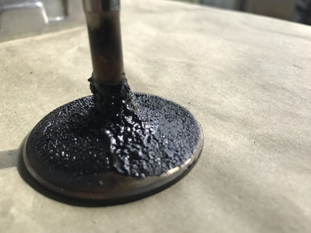
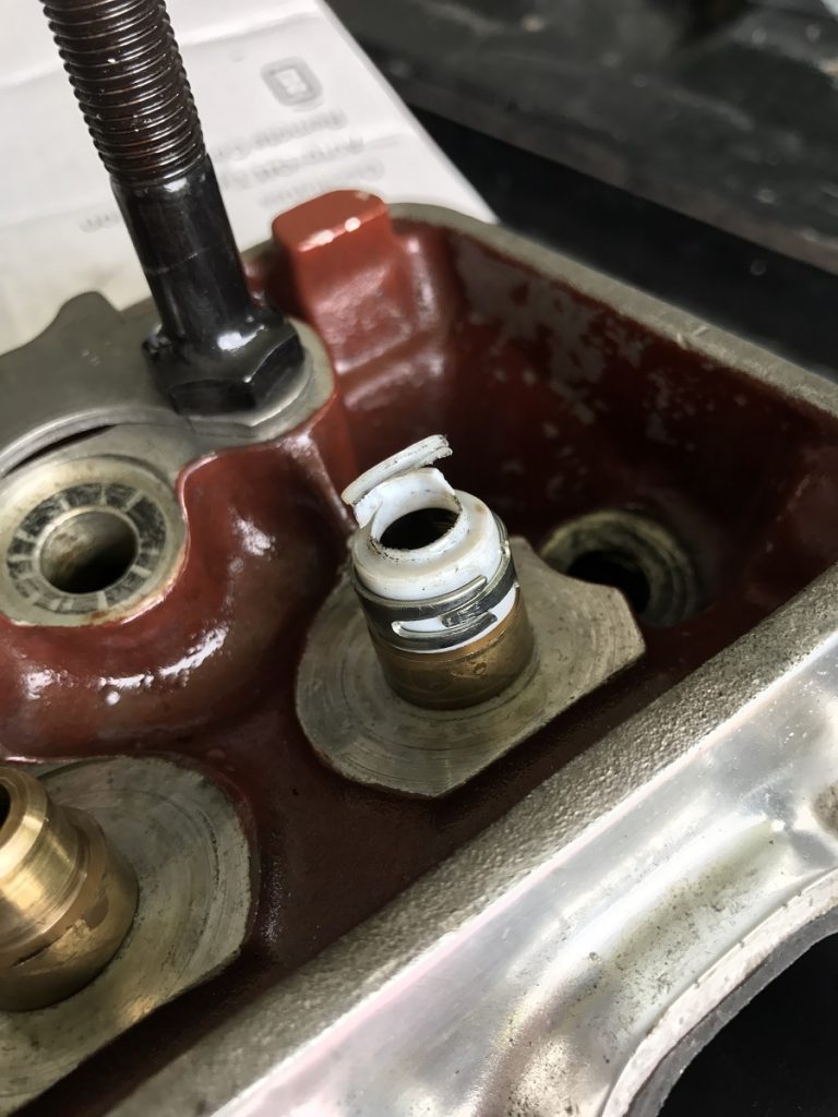
Until recently the engine ran great and made good power. But then it started to run rough and it lost mph at the track. I also noticed it started to foul a couple of plugs. When I pulled the heads, I found this very crusty intake valve along with a torn valve guide seal. I’ve included a photo of both the seal and the valve. Should I just replace the seal and put it all back together? I’m worried that whatever failed this seal will happen again. Not all the seals looked this bad. I also noticed that the #8 exhaust valve has kissed the piston. I checked the piston and it has only a very slight mark but the valve is bent. I will replace the valve but what else should I do? — T.M.
…
Jeff Smith: This is a really high-rpm situation and right off it appears that your valve seal problem is a direct result of a loss of valve train control.
Control of the valves is directly related to spring pressure but that load is affected by multiple factors. The most important variables are lobe design, weight of the valves and retainers, rocker arm design, rocker ratio, and the strength of the pushrods.
The actual damage to the seal could be from the retainer hitting the seal and damaging it. It can also be a result of loose valve-guide clearance.
I would start by checking this guide clearance especially on the exhaust side. These PC-style seals are not very compliant and if the guides are even slightly worn — which is common on small-block Chevys with big cams — this sideways motion could damage the seal. If you can fit a Viton rubber-style seal inside your dual valve springs, that would be a better solution.
In terms of overall performance of the valve train, let’s start with the valve springs.
In a follow-up email, Tom told us that his current valve springs are a COMP Cams PN 954-16.
This spring’s specs are listed in a spec box below, but with a rate of 483 pounds per inch (lbs./in.), this spring is generally installed at 1.850 seat height that produces a load of 234 lbs. This is the spring that COMP recommends for a similar duration and lift mechanical roller cam so the spring is likely capable of controlling the valve.
| COMP Cams 954-16 Valve Spring Specs | |
|---|---|
| Spring O.D. | 1.536 in. |
| Spring Rate | 483 lbs./in. |
| Installed Height | 1.900 in. |
| Seat Load | 210 lbs. |
| Open Load | 524 lbs. at 0.650 in. |
| Coil Bind | 1.170 in. |
| Maximum Lift | 0.650 in. |
…
This means we should look in other places for where the problems lie.
The best way to evaluate a valve train is to look at it as a whole system rather than the individual parts. When this engine is spinning to 7,000-plus rpm, the acceleration rates on the valve train are enormous.
Adding to this issue is the rocker arm ratio. The standard small-block rocker ratio is 1.50:1. This increases lobe lift by 50 percent, but also accelerates the valve open and closed at that same increased rate. This higher load is then transferred to the pushrod.
For example, at near maximum lift this spring will require 500 lbs. of force to move. Then we multiply that times 1.5 and generate 750 lbs., which is being fed back into the pushrod.
But these are just the static loads. At 7,000 rpm the inertial loads are incredibly high. Our friend Billy Godbold at COMP Cams tells us that it is not unusual for a small-block Chevy valve train to experience acceleration g-forces in the neighborhood of 1,500 g’s. With a 115-gram pushrod at those acceleration forces, the pushrod alone would weigh nearly 380 pounds. This gives you an idea of the forces that the spring must be able to control.
The valve spring’s job is to not only control the valve, retainer, and locks, but also the spring itself as well as the inertia of the rocker arm and pushrod. Since it would appear that this spring is a decent choice, we must look in other areas.
One way to easily reduce the loads the spring must control is to reduce the mass of the system to be accelerated.
We’ll assume that you are probably running a 5/16-inch pushrod with an 0.080-inch wall thickness. If not, this is an absolute minimum upgrade. If the current pushrods are already 0.080-inch wall versions, consider improving these with a 0.105-inch wall thickness chromoly pushrod. COMP Hitech’s, Summit HDR’s, and others offer these stronger pushrods that will help minimize deflection under load.
One way to easily reduce the loads that the spring must control is to reduce the mass or weight of the system must to be accelerated.
We’ll assume that you are probably running a 5/16-inch pushrod with an 0.080-inch wall thickness. If not, this is an absolute minimum upgrade. If the current pushrods are already 0.080-inch wall versions, consider improving these with a 0.150-inch wall thickness chromoly pushrod. COMP Hitech, Summit HDR, and others offer these stronger pushrods that will help minimize deflection under load.
The next place to consider is a lighter retainer. We’ll assume you are running a standard steel retainer. While everybody knows that titanium retainers are lighter, they are also expensive and not as strong as steel.
However, there is also a tool steel retainer sold by COMP that is nearly as light as titanium at half the cost. We measured a typical steel retainer for a dual spring at 30 grams and compared it to a tool steel version at 15 grams. This is a 50-percent weight reduction.
If we assume this 7,000 rpm small-block is experiencing 1,500 g’s of acceleration, this 15-gram reduction in weight immediately reduces the load the valve spring must control by a touch over 50 lbs.
When you consider that this also reduces the stress on the spring and valve which will improve durability, it might be worth the investment. We priced both sets. The tool steel retainers cost $180 versus $55 for the regular steel retainers.
The reason the exhaust valve hit the piston is because the springs lost control.
We often see exhaust valves hit the piston rather than the intake valves. This could be because of tighter piston-to-valve (P-V) clearance, which is something else that must be checked before re-assembling the engine.
While most people just perform the clay method, which does work, we prefer the valve drop method with a dial indicator because it is more precise.
There are several stories online that will outline the procedure. Sometimes just changing the camshaft intake centerline will improve the clearance.
Advancing the cam will increase exhaust P-V clearance and decrease the intake valve P-V. Retarding the cam will create the opposite effects. So if this engine has minimal exhaust valve P-V and plenty of intake clearance, then advancing the cam will help this situation. Don’t advance the cam more than four degrees.
Of course, establishing the correct pushrod length also helps valve-train stability. The approach is to position the rocker roller tip to move across the center of the valve stem tip. This is easily accomplished by custom-setting the correct pushrod length. This is covered in several online magazine articles and should be easy to find.
Combine all or most of these efforts should improve the valve train stability. Of course, reducing the shift point will also help, especially if, through testing, that reducing the shift point improves the trap speed. This is the easiest way to determine if a change you make is positive. Even a 200 to 300 change in rpm can make a huge difference in both stability and durability.
Hi, Jeff, what is your email address so I can ask some questions about my sbc engine? Thanks Brian.
Good morning Jeff i recently striped my 350 because of loss of compression over the last 3 years. 5000 miles + 3 checks 190-120lbs Rings+ pistons look good no blow by. Valve seals look good and the stems mike good. Tops of pistons look oily or gummed as well with the valve backsides. To me it looks like bad seals but i think not. my roller rockers have a .090 orifice compared to .060 on other rockers Could i be filling the covers with oil + flooding the seals? I hope i have given enough info? Thanks for your time have a great day Gary
Thanks for the quick reply yesterday. Most of the pressure drop is on the left side #1 is 190 #3 125 #5 150 #7 165 the even bank is 190 200 190 180 lbs. I have hasterly cleaned the valves so a good report is not possible most exhaust valves were gummed. Intake very clean underside and ports . This engine has used oil 1 qt. 500 miles since new . All chambers hold liquid good with heads up, valve seats look good .10-1 static com. comp 230-236 split roller, cam 510 530 lift ,eddy air gap 750 holley 195 profiler heads alum. dyno when fresh 436 tq. 450 h.p. Does windage have a factor here? Thanks soo much for your time. Gary