Drum brakes were
standard equipment for decades. Even high-powered muscle cars were equipped
with drum brakes on at least one axle.
Many were
equipped with drums on the front too.
Drums can
fade. They’re affected adversely by water. They require adjustment periodically.
The reality
is, disc brakes are superior when it comes to stopping power.
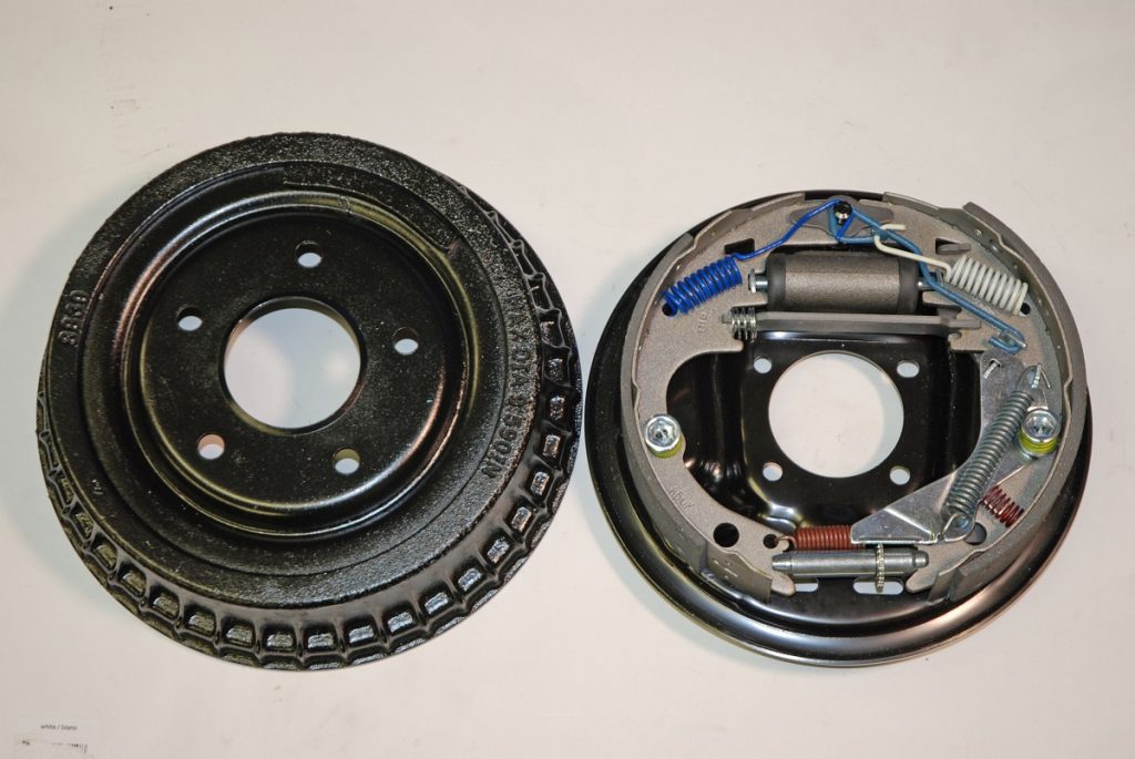
They’re simpler too. A typical set of drum brakes can have dozens of individual parts, you have to deal with all of them correctly in order for the brakes to function properly.
While it’s relatively easy to toss the drums and get a disc brake kit, many owners want to keep their cars original, including the original drum brake system.
There are options.
For example,
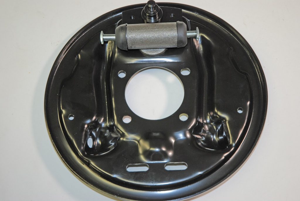
you can purchase backing plates that are already “loaded.”
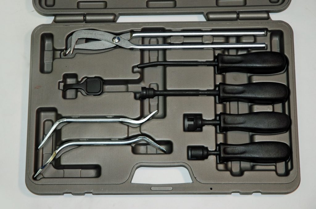
But assembling a set of drum brakes isn’t that tough. Certainly, there a number of parts involved, some which require a bit of finesse, and you’ll need some special tools too.
Once the
drums have been turned (by a brake shop, if necessary) the job isn’t difficult.
Parts aren’t
hard to find either.
For a closer look at how it’s done, check out the accompanying photos and captions:
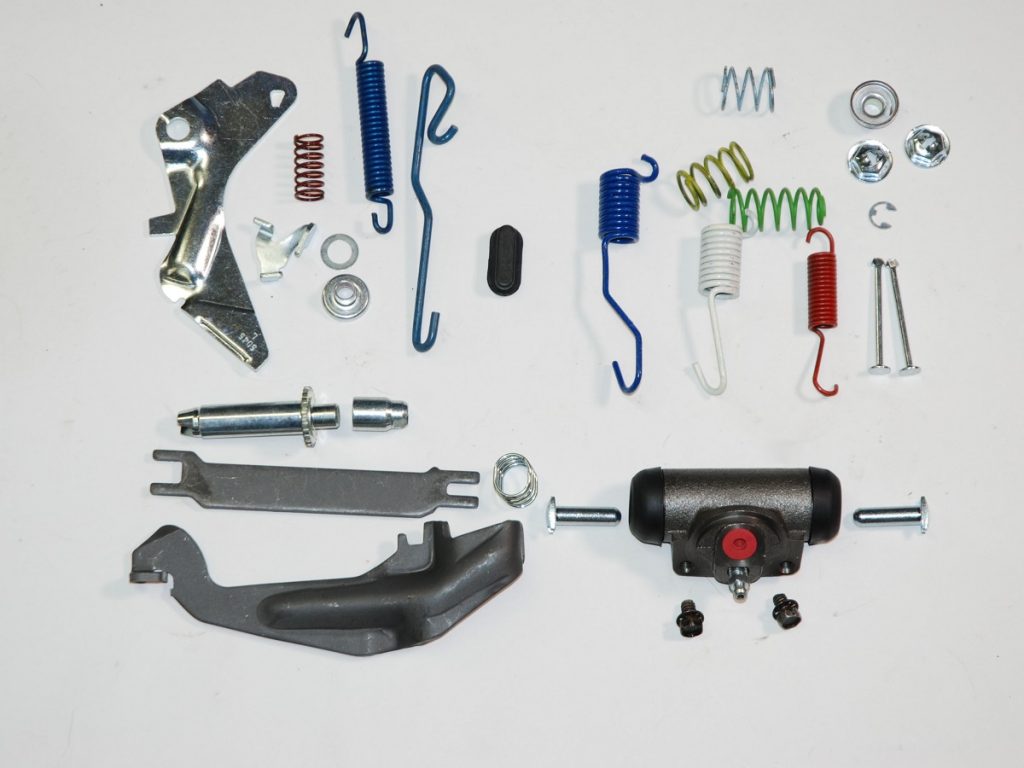
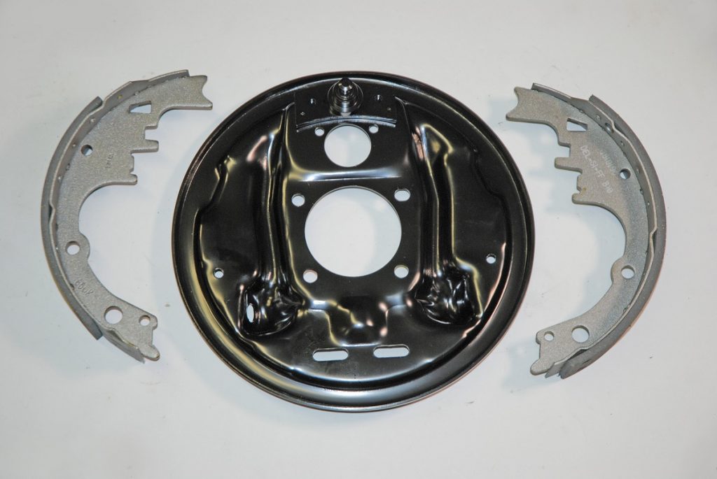
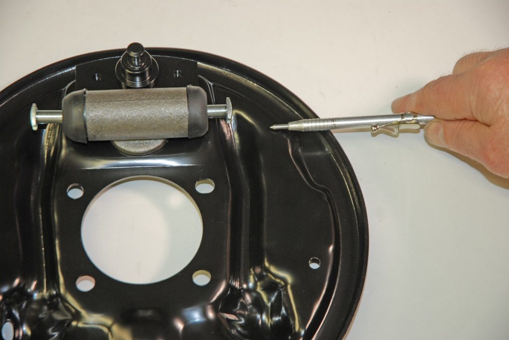
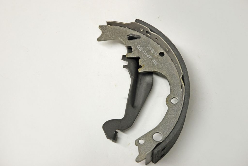
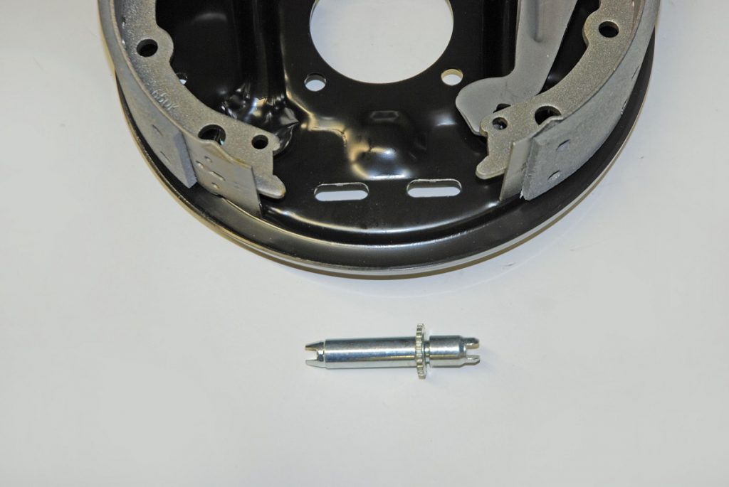
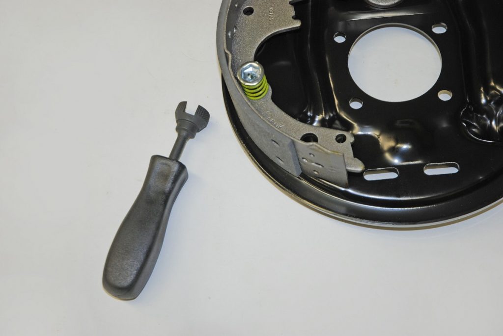
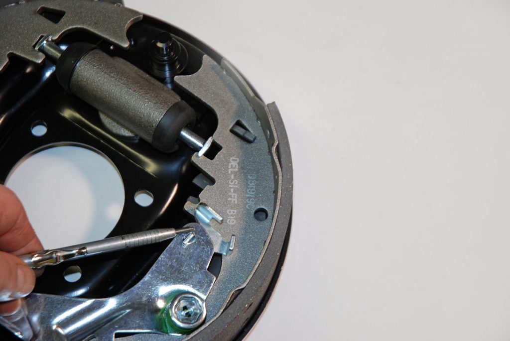
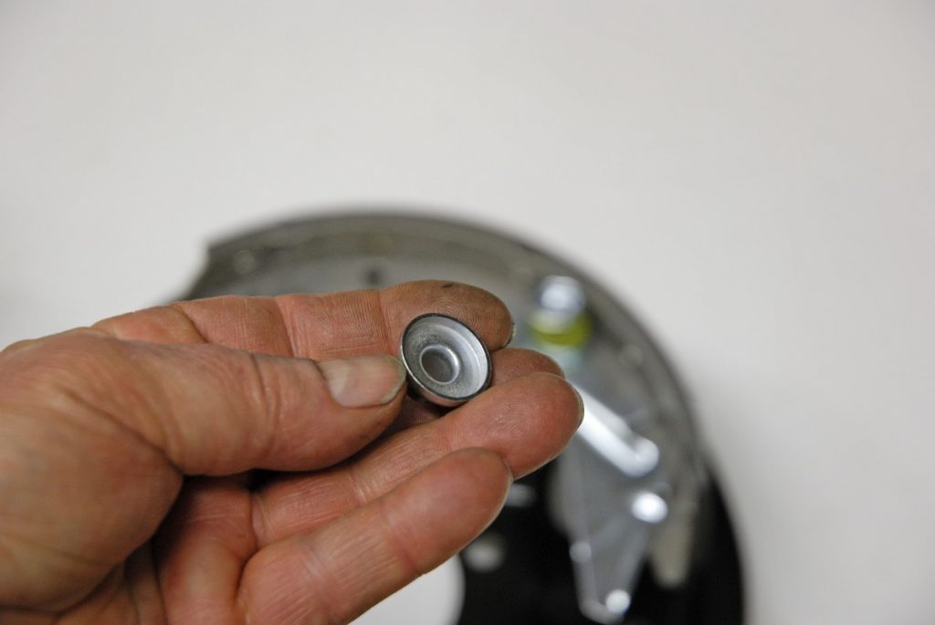
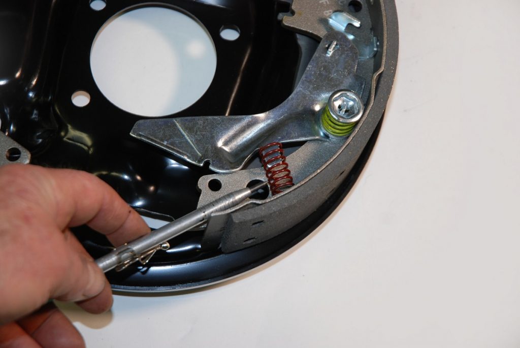
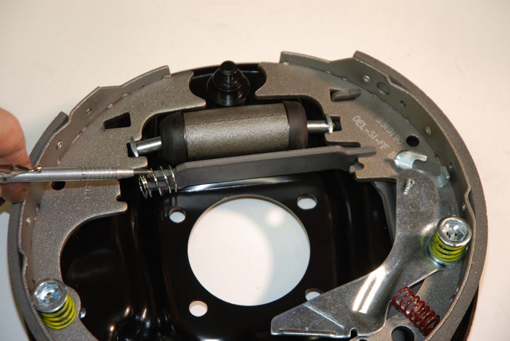
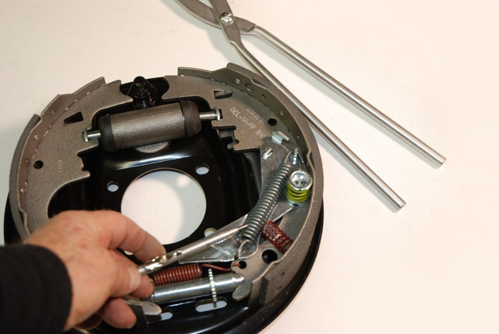
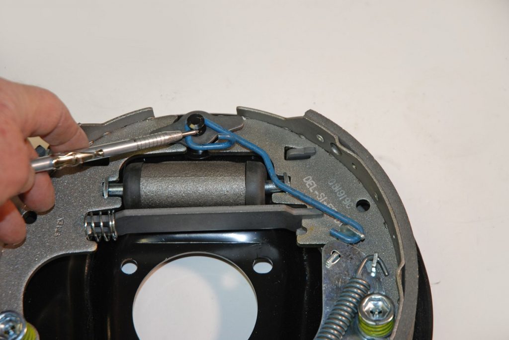
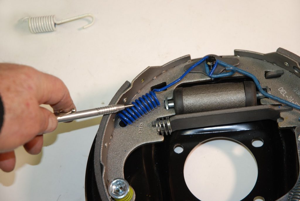
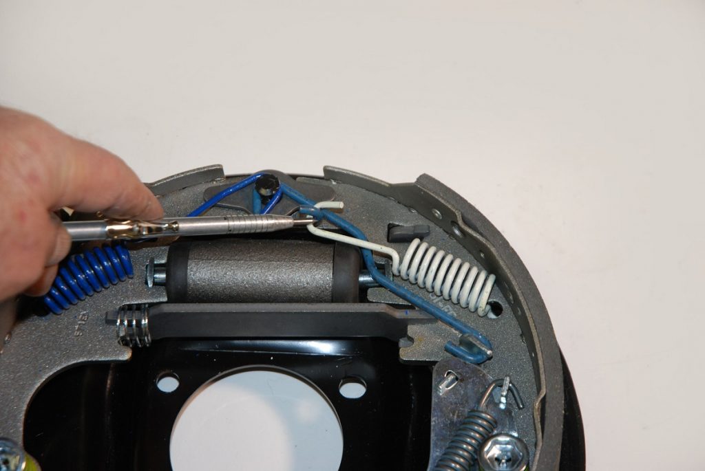
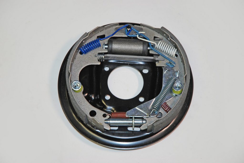
Before you go any further on a drum brake job, you’ll need tools. This is an all-inclusive OTC tool set sold by Summit Racing. You’ll also need some brake cleaner if you’re working with used parts along with a small amount of synthetic grease (not shown). Gloves and eye protection are good ideas too. (Image/Wayne Scraba)Summit Racing sells these new backing plates for 9.5-inch GM applications. They’re the solution when it comes to rusty, pitted and damaged OEM examples. (Image/Wayne Scraba) Here’s a look at the collection of little parts you’ll need in order to assemble (and completely rebuild) one rear drum brake. You’ll have to reuse some of your original park brake hardware. (Image/Wayne Scraba) Begin the assembly process with the wheel cylinder(s). They’re installed as shown here. They can only go in one way. During assembly, it’s a good idea to lightly lube the pushrods. They’re definitely subject to corrosion. (Image/Wayne Scraba)Brake drum parts are typically “sided” left and right. It’s easy to figure out: The opening for the e-brake cable faces forward. The brake shoe on the right is longer than the one on the left. The RH or longer shoe is the trailing shoe. The leading shoe is shorter. (Image/Wayne Scraba)The backing plates should be lubricated before going any further. The backing plate has a raised surface. That’s where the lubricant is applied. The idea here is ensure the lube does not come in contact with the brake shoe (lining) surface. If it does, clean it with brake cleaner. (Image/Wayne Scraba) The park brake lever fits into the trailing (longer) shoe. It slips in from behind, and in most cases, it must be assembled before the shoe is assembled onto the backing place (although we’re skipping the cable for this series of photos). (Image/Wayne Scraba)Next up is the adjuster. First, lightly lubricate the threads. It’s not uncommon to come across seized adjusters and the reason is they were never lubed. The easiest way to install them is to hook up the spring first with the shoes off the backing plate. Then hook one end of the adjuster into one shoe. With a little bit “finesse”, you can work the second side of the adjuster in place on the opposite shoe. The adjuster wheel is closest to the park brake lever. The spring can only be installed one way so that it clears the wheel on the adjuster. (Image/Wayne Scraba)Both the leading and trailing shoes are held in place by a coil spring perched over a “nail.” Here, the leading shoe incorporates a beehive spring. The OTC spring installation tool is used to compress the spring while the nail (which passes through the back end of the backing plate) is held in place. A quick turn of the tool allows the nail to seat in the spring retainer. Note the retainer has two recesses designed to lock in the nail. (Image/Wayne Scraba) The self-adjuster actuator lever is located on the face of the trailing (back) shoe. Examine the actuator lever closely. You’ll find there is a small secondary hook that slips into place. That hook is for the return spring (more later), however it must be installed now. You’ll never get it on later! (Image/Wayne Scraba)You’ll find the coil spring for the actuator differs from the one found on the leading shoe. In this case it’s a flat bottom job that requires a spring seat. The spring seat installs in the actuator lever and is followed by the spring and retainer. The spring tool is used to compress the spring while the nail is held in place. Seat the nail in the retainer. (Image/Wayne Scraba)Note the flange on the actuator? This is where the small bumper spring is located. It simply slips into place. Once the other springs are in place, the bumper spring will be kept under tension. (Image/Wayne Scraba)The park brake strut is installed next. You’ll likely have to re-use your existing strut. Note the spring at one end. It fits on the leading shoe side. The slot in the strut also engages the park brake lever. To install, spread the shoes apart slightly and insert the sprung end of the strut into the primary shoe. Slide the shoes back together. (Image/Wayne Scraba)The actuator pull-back spring is installed. Install the lower hooked end first. Next, with one end of the brake pliers handle inserted through the spring eye (the OTC pliers work here), stretch the spring out and over the tab on the pawl. The idea is to lever the spring body in place and guide it with your free hand (gloves are definitely a good option!). The actuator lever body is designed with a recess for the spring body. The spring only installs one way. (Image/Wayne Scraba)The link for the actuator installs next. Insert the anchor guide over the anchor pin. Hook the actuator link to the pawl as shown here. If the shoes are pushed tight at the top (at the anchor), it’s sometimes possible to slide the other end of the link over the anchor. If not, use the brake pliers to slide it over the pin. (Image/Wayne Scraba)The leading shoe spring installs next. Hook the brake shoe end in first, and then, using the pliers, work the spring over the anchor pin as shown here. (Image/Wayne Scraba)The trailing shoe spring is the final piece in the backing plate puzzle (aside from the park brake cables). The spring must be attached to the shoe first, but instead of hooking directly to the anchor pin, the opposite end attaches to the open end of the actuator link. (Image/Wayne Scraba)Here’s the finished product. It’s not a super-difficult job and it’s something you can definitely do yourself with the right collection of parts and of course, the right tools. (Image/Wayne Scraba)
Wayne Scraba is a diehard car guy and regular contributor to OnAllCylinders. He’s owned his own speed shop, built race cars, street rods, and custom motorcycles, and restored muscle cars. He’s authored five how-to books and written over 4,500 tech articles that have appeared in sixty different high performance automotive, motorcycle and aviation magazines worldwide.
Comments
8 responses to “How to Assemble Drum Brakes (A Step-by-Step Guide)”
Depends on what kind of brake system(manufacturer)also. I’ve been doing Drum Brakes for years.And yes Disc Brakes are far better.A lot of trucks still use Drum Brakes(semi’s) they both have there pro’s & cons.
You might have mentioned the adjuster is usually marked for the side of the vehicle it came off of – in the event they have both sides apart and cleaning up the parts, as I have seen them installed on the wrong side, and of course, the brakes don’t “self adjust”.
I remember my dad sending me down the street to help a 40+ year-old man change his drum brakes. I was about 10 and it was 1960 something. My tools consisted of three straight slot screwdrivers of various sizes and a variety of pliers. The man was a carpenter so I didn’t have to worry too much about tools. In those day everyone kept the biggest bumper jack out of all the cars they had ever owned. Everyone had a star jack for removing the nuts but just like the bumper jack you could find crow bars in every junk yard but they were really breaker bars for a specific car. If you found a whopper you took it and threw it in the back of your pickup. I find it harder to replace drum break nowadays. I bought a tool kit but it takes too much time figuring out what they all do.
This is an excerpt from an old buick manual. “It is very important that parking brake cables are not adjusted too tightly to cause brake drag. With automatic brake adjusters, a tight cable causes brake drag and also positions the secondary brake shoe, hence the adjuster lever, so that it continues to adjust to compensate for wear caused by the drag. The result is a cycle of wear and adjustment that can wear out linings very rapidly. “

These were the simple brakes. There are ones with more parts to them. But it’s a good start.
Leading? Trailing? I just remember “big shoe to the back”
Depends on what kind of brake system(manufacturer)also. I’ve been doing Drum Brakes for years.And yes Disc Brakes are far better.A lot of trucks still use Drum Brakes(semi’s) they both have there pro’s & cons.
You might have mentioned the adjuster is usually marked for the side of the vehicle it came off of – in the event they have both sides apart and cleaning up the parts, as I have seen them installed on the wrong side, and of course, the brakes don’t “self adjust”.
I remember my dad sending me down the street to help a 40+ year-old man change his drum brakes. I was about 10 and it was 1960 something. My tools consisted of three straight slot screwdrivers of various sizes and a variety of pliers. The man was a carpenter so I didn’t have to worry too much about tools. In those day everyone kept the biggest bumper jack out of all the cars they had ever owned. Everyone had a star jack for removing the nuts but just like the bumper jack you could find crow bars in every junk yard but they were really breaker bars for a specific car. If you found a whopper you took it and threw it in the back of your pickup. I find it harder to replace drum break nowadays. I bought a tool kit but it takes too much time figuring out what they all do.
[…] How to Assemble Drum Brakes […]
what would let this brake keep adjusting too tight, It’s on right but won’t stop over tightening, I’m about ready to bend the adjusting arm away
This is an excerpt from an old buick manual. “It is very important that parking brake cables are not adjusted too tightly to cause brake drag. With automatic brake adjusters, a tight cable causes brake drag and also positions the secondary brake shoe, hence the adjuster lever, so that it continues to adjust to compensate for wear caused by the drag. The result is a cycle of wear and adjustment that can wear out linings very rapidly. “