(Image/Wayne Scraba)
Having the capability of monitoring what’s going on inside a hot rod or race car is pretty important.
Gauges are critical—that’s no secret, but when you start digging you’ll soon discover there are all sorts of gauges available.
There are really big differences between various gauges too, and what works for a pro might not be so cool for a weekend warrior or hot rodder.
Some gauges are better suited to racing than others. Some are more complex than others and yes, some are more (sometimes much more) costly than others.
Fair enough, but one thing we’ll address before going any further is the fact that there are only so many gauges you can monitor in a drag car during a quarter mile pass. Sure an instrument cluster that is one step away from the cockpit of an old P-51 Mustang is impressive, but something like an aircraft cluster isn’t exactly easy to scan during a quick pass down the quarter mile.
You’ll note we used “big gauges” (2-5/8-inch diameter) for this article. There’s a reason for that: they’re much easier to read at a glance and there’s more ‘room’ between the gauge face graduations. Yes, there are gauges available with larger faces, but they’re much more difficult to package because they take up more room.
While digital instruments are an option, we didn’t include them here because they can be difficult to read at a split-second glance.
***
Oil Pressure Gauges
The most important instrument in the car is the oil pressure gauge. The instrument of choice for most racecars is a mechanical gauge. There are a number of different mechanical gauges on the market, but one consideration is the overall range of the gauge. For example, Auto Meter manufactures 2-5/8-inch mechanical oil pressure gauges in 0-100 PSI, 0-150 PSI, and 0-200 PSI ranges.
Which one is right for your application? It depends upon the engine.
If your combination will never see the high side of 70 PSI, then it makes no sense to install a gauge that will read 200 PSI. In simple terms, a gauge with fewer markings is easier to read than one with larger markings. That’s why manufacturers such as Auto Meter purposely skew the face on many of their instruments. This allows the area of maximum pressure to be situated at the top of the instrument.
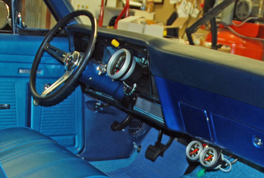
Ideally, an oil pressure gauge should be installed in your line of sight, but in many applications, that’s easier said than done. This is especially true if you have a tach on the dash along with a fuel pressure gauge mounted on the cowl. Things get a bit crowded.
The next logical location for these instruments is in the dash. Mounting gauges is another exercise in compromises. (See why in the photos below.)
There are a number of ways to plumb a mechanical pressure gauge, but by the text of most sanctioning body rulebooks, you must use some form of metal or metal encased line. Plastic hose doesn’t cut it.
One of the best ways to plumb a mechanical oil pressure gauge is by way of braided stainless steel line. For the vast majority of applications, good old-fashioned neoprene-lined AN hose is suitable (Teflon lined hose is acceptable as well, but keep in mind this hose can’t make tight-radius bends).
A neat trick when plumbing a mechanical oil pressure gauge is to use an AN bulkhead fitting on the firewall. This way, you can run a hose from the gauge to the firewall and another hose from the firewall to the engine.
Water Temperature Guages
The second most important gauge has to be water temperature. Mechanical water temperature gauges are also very common, but they have one major drawback: the capillary tube is often fragile, particularly after extended use (and regular removal and replacement). It can be kinked or damaged during installation. If you damage the tube, you’re forced to send the gauge back to the manufacturer for repairs.
There’s another option: Auto Meter offers stepper motor-based electrical temperature gauges. The stepper motor configuration allows for a full gauge sweep (unlike old electric gauges). It also does away with the capillary tube.
Another recent innovation in the world of racing instrumentation is the “low temp” water temperature gauge. Where standard mechanical gauges usually begin their face calibration at 120° F and end at anywhere from 240° F to 280°, Auto Meter’s “low temp” stepper motor gauges begin at 60° F and end at 210° F.
Why is this range superior to a standard gauge? That’s easy: it stands to reason that when you cool a something like a drag race engine between rounds, you’re making an effort to bring the engine temperature close to ambient temperature. When the ambient temperature is 75° F, and the lowest the gauge reads is 120° F, there’s no way of knowing how cool the engine really is. When cooling the engine, then you’re just guessing that the temperature is 120° F or less.
According to Auto Meter: “Water temperatures can be monitored coming out of the staging lanes, into the burnout box and coming up to the starting line. This gauge allows drivers to monitor the critical engine warm up as they stage. Never before have drivers been able to accurately read this crucial temperature range.”
In order to produce a water temperature gauge with this low range, Auto Meter had to take a different engineering approach. Auto Meter used a combination of electric gauge technology mixed with technology garnered from their data acquisition program. The electric water temperature gauge is transducer-based, and it’s hooked up by way of a plug-and-play harness (more on this technology below).
When dealing with any water temperature gauge, the basic temperature probe should be located in the water jacket (some people prefer an intake manifold water cross-over for the probe location, while others prefer to install the probe directly into a cylinder head).
In a typical mechanical gauge application, some engines require a 1/2″ NPT adapter nut for the probe installation; others require a 3/8″ NPT adapter. Once the adapter is installed, insert the sensor and carefully tighten the sealing nut (which is part of the capillary tube assembly).
A coating of anti-seize compound on the sealing nut is a good idea. Don’t over tighten the nut. Auto Meter recommends a quarter-turn beyond snug to make the connection. In addition, you’ll have to cut a 7/8″ hole in the firewall so that the probe and accompanying hardware can pass through.
Fuel Pressure Gauges
Third on our must-have list is the fuel pressure gauge.
Fuel pressure gauges are as common as oil pressure gauges in drag racing, but this is one instrument that requires added thought, especially with regard to mounting.
Given the fact that raw gasoline is found in the line running between the gauge and the source, a fuel pressure gauge should never* be mounted inside the vehicle.
*According to Auto Meter, there are two exceptions to this rule: a mechanical gauge that uses an “isolator” and an electric gauge.
The isolator arrangement is based upon a remote, mechanical system of “powering” the gauge, allowing it to be mounted within the cockpit. Basically, the pressure side of the fuel delivery system is tapped and gasoline is pumped to the isolating device mounted in the engine compartment. Inside the device is an inert fluid (often glycol-based). Fuel pressure forces the inert fluid through a stainless steel braided line to the gauge. Because of this, fuel never enters the gauge and consequently, never enters the cockpit, which makes it failsafe.
Reliable full sweep electric fuel pressure gauges are relatively new. Obviously, they incorporate an electrical sender plumbed within the fuel line and then incorporate wires to transmit the information to a cockpit mounted gauge. Typically, an electric gauge will be limited to a needle sweep of 90° while a common mechanical gauge will have a needle sweep of 270°.
By increasing the range (sweep) of the needle, then the gauge is easier to read and you can obtain quicker, more accurate readings. When designing their electric stepper motor fuel pressure gauge, Auto Meter took this into consideration, but there’s more to it than that. Most aftermarket electric fuel pressure gauges are based upon a converted oil pressure gauge.
According to the engineering staff at Auto Meter, a conventional sender (like the ones used in electric oil pressure gauges) is based upon a simple diaphragm that measures resistance. This type of sending unit isn’t completely accurate when measuring fuel pressure. It also has a tendency to fail when introduced to more exotic racing fuels (including alcohol and nitro methane).
Auto Meter took a different approach. Instead of a sender for their line of stepper motor pressure gauges, they make use of a transducer-plumbed in-line. As we pointed out earlier, this transducer arrangement is similar to the components incorporated in data acquisition systems. Transducers measure voltage as opposed to resistance. Wiring is straightforward: a plug and play harness is used between the transducer and the gauge. An additional wire goes to ground, one wire powers the gauge lamp and one wire goes to a (fused) 12-volt terminal on the ignition switch.
If the isolator doesn’t fit your needs, and you don’t want to try one of the new electric fuel pressure gauges, you then have a couple of mounting choices for a mechanical fuel pressure gauge: mount the gauge directly to the fuel system (i.e. the regulator) and read it only when you set the pressure. The other option is to mount the gauge on the outside of the car so that you can monitor it during a pass. The captioned photos offer suggestions on external mounting.
Voltmeter Gauge
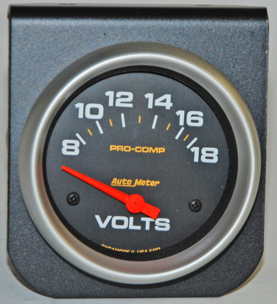
The last gauge on our must-have list is the voltmeter. Why use a voltmeter instead of an ammeter?
Auto Meter manufactures both instruments, but offers this advice: “Which is better for monitoring a vehicle’s electrical system: a voltmeter or an ammeter? The short answer is simple: a voltmeter, by far.”
The ammeter is basically a flow meter. It measures the current flow to the battery. What that means is the entire electrical ‘flow’ in the charging system has to pass through the ammeter; all of the alternator output used to recharge the battery must first be routed through the ammeter mounted in or under the dash.
This requires a heavy-gauge cable and presents a potential fire hazard. The ammeter itself must be able to handle all this current flow, so it must have a higher current rating than the alternator’s maximum rated output.
According to the experts “when the alternator recharges a ‘low’ battery, the ammeter indicates a high charge rate; with a fully charged battery the voltage regulator reduces alternator output, and the ammeter is supposed to indicate a very low charge rate.”
“But how can you really tell the voltage regulator has reduced alternator output because the battery is fully charged? Perhaps a diode in the alternator rectifier failed, or the alternator belt slipped once it warmed up, just as if the battery were fully charged. Or maybe the ammeter indicates a medium charge rate most of the time. You have to ask yourself if the battery really needs this much or could the voltage regulator be overcharging the battery?”
Then there’s the case of the voltmeter. It works like a fuel pressure gauge, but instead of measuring pressure in PSI, the voltmeter measures electrical system ‘pressure’ in volts. Just like a fuel pressure gauge, a voltmeter only needs to tap into a circuit; all the fuel (or electricity) does not have to detour through the gauge for it to function. Voltmeter installation is easy, quick, and safe: It hooks up to a fused, ignition-switched “off/on” source.
In operation, the voltmeter directly measures the result of charging-system performance. With normal alternator/voltage-regulator function, battery voltage is maintained at 14.0 to 14.5 volts-and this is reported directly by the voltmeter. In the event of alternator-system failure, voltage will be low and continue to drop as the battery discharges. In the event of an “overcharge” condition, the voltmeter will climb above its normal zone.
While a voltmeter can easily be installed in the cockpit (and it probably should be in a street-driven car), the vast majority of drag racers take a different approach: they mount the voltmeter so that it’s visible when charging the battery between rounds.
If your race car has a rear-mount battery, then the gauge is mounted in the rear, near the battery. If your battery is up front, then mount it under the hood. That way, you can keep an eye on its charging status as you perform other between-rounds maintenance.
***
When all is said and done, picking the right combination of gauges for racing or a hot rod isn’t that complex. Sure you have a lot of choices, but the good news is that technology garnered from sophisticated data acquisition devices has trickled down into conventional instrumentation and is now not only affordable, it’s readily available.
See the accompanying photos for more.
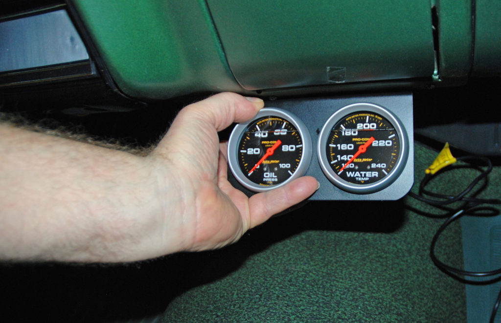
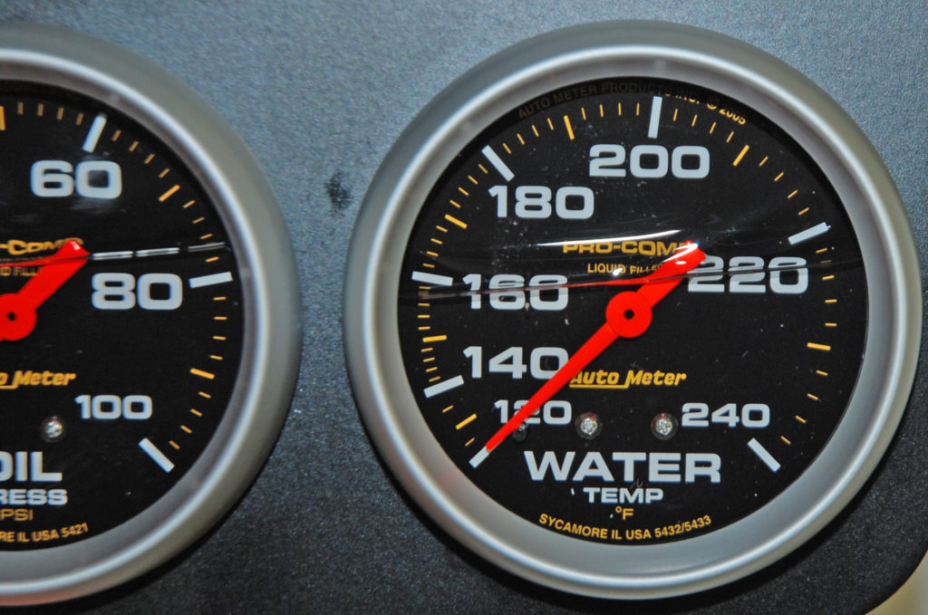
Two instruments that are absolutely critical in a race car are the oil pressure gauge and the water temperature gauge. Ideally, these gauges should be installed in the line of sight, but in many applications, that’s easier said than done. (Image/Wayne Scraba)
A logical location for these instruments is under the dash. The requirement of mechanical instruments precludes a number of mount locations. Usually, the associated lines require large sweeping bends instead of a tight radius. Furthering the mount problem is available dash panel space. If the under dash location proves to be the only option, then be sure that the gauges are big, uncomplicated and easy to read, like these 2-5/8-inch Pro Comp gauges from Auto Meter. (Image/Wayne Scraba)
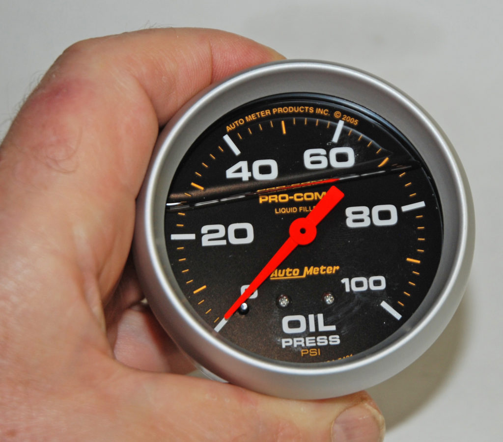
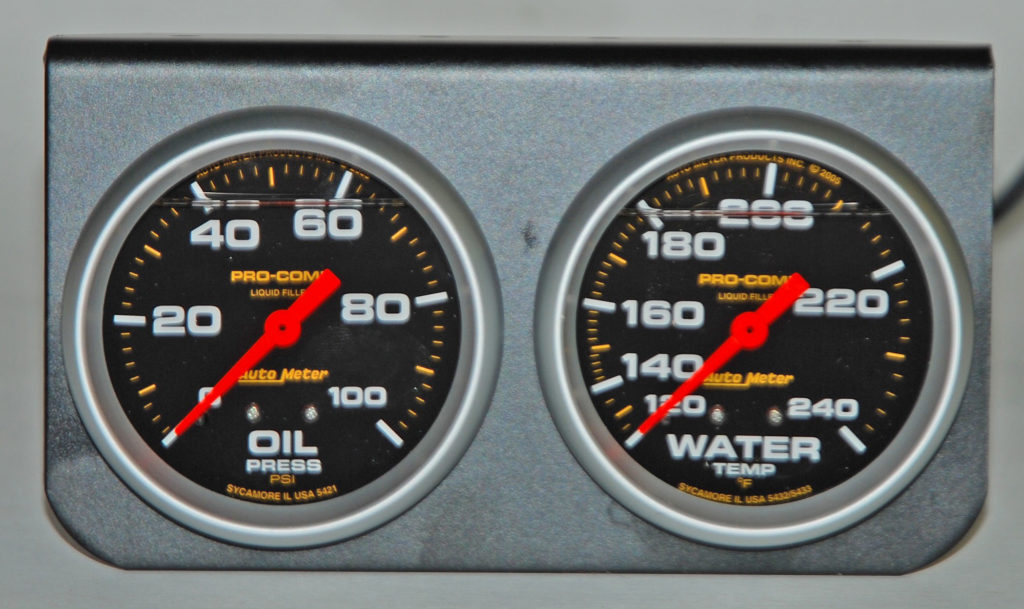
Gauge range is important. For example, this mechanical oil pressure gauge reads from 0 to 100 PSI. For our application (a rather conventional big block Chevy), there’s no need for a gauge that reads higher. (Image/Wayne Scraba)
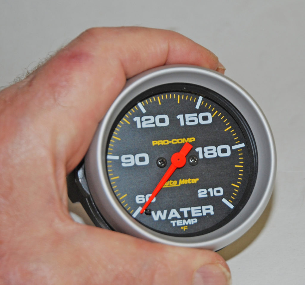
Speaking of gauge range, check out the range on this stepper motor electric water temperature gauge. It reads from 60 degrees to 210 degrees. It’s perfect for drag racing—more info in the story above. (Image/Wayne Scraba)
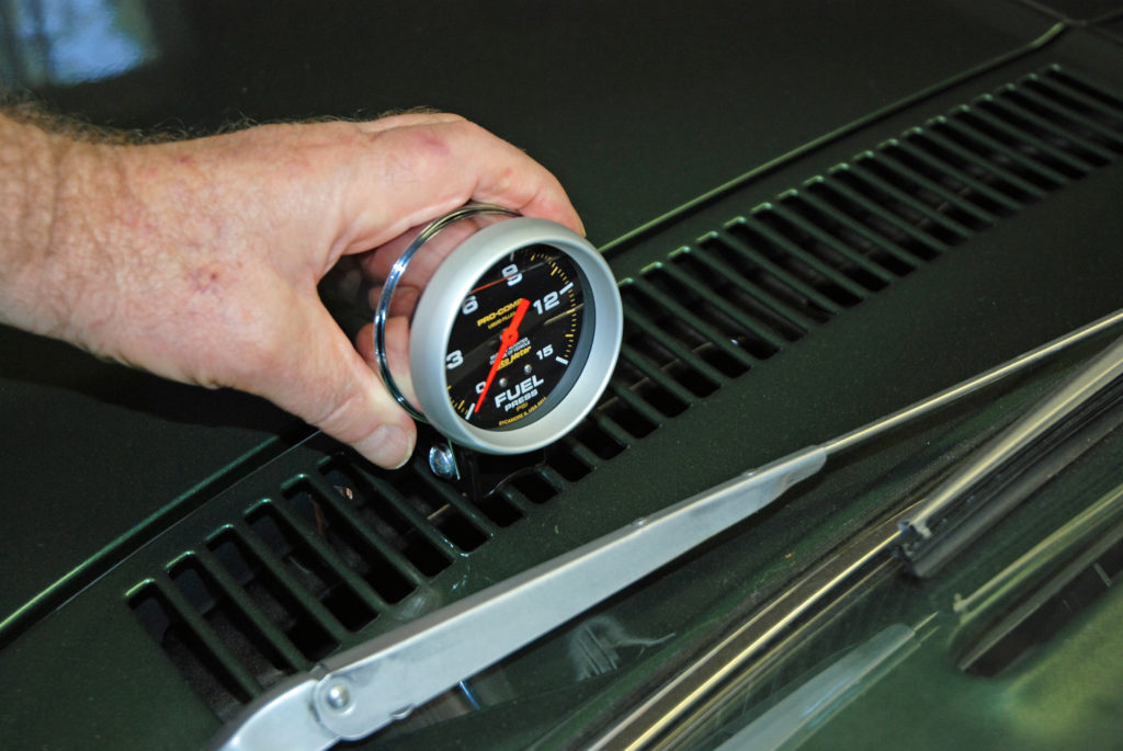
One gauge that requires extra mounting consideration is a mechanical fuel pressure gauge. Because raw gasoline is found in the line running between the gauge and the source, the fuel pressure gauge should never be mounted inside the vehicle (check your rulebook, it spells out the mounting location). The story above offers a couple of other options too (gauges with isolators and electric stepper motor gauges. If you mount the gauge outside the car (using a cup as shown here), watch the mounting location carefully. Things like the dash, the steering wheel, or even a dash-mount tach might obscure the gauge. (Image/Wayne Scraba)
It’s a good idea to test-fit the gauges before you bolt them in place. You might be surprised to find that a bit of angle on the mount hardware can make under-dash gauges much easier to read. Similarly, it might be easier to view the gauges is they are actually moved away from the shifter instead of being position closer to the driver. With this set up, you might be able to view the gauges by moving your eyes instead of your entire head. The result is less time taken away from watching the track. (Image/Wayne Scraba)
While a voltmeter can easily be installed in the cockpit, many racers have a different strategy: they mount the voltmeter so that it’s visible when charging the battery between rounds. That way, you can keep an eye on the charge as you perform other between-rounds maintenance.
(Image/Wayne Scraba)
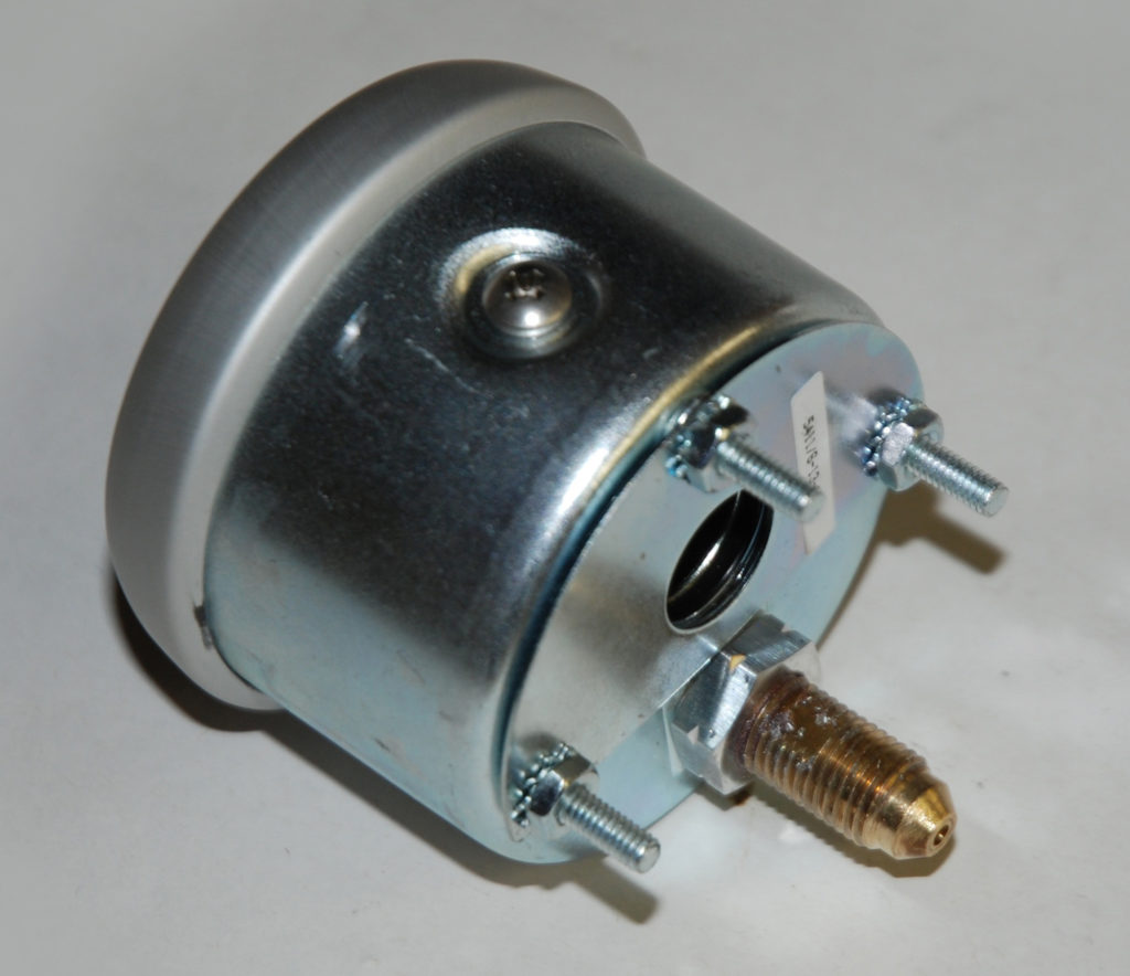
One type of instrument that regularly sees use in drag racing and high performance street cars is the liquid filled gauge. Auto Meter pioneered the use of this technology for high vibration, high shock load applications. In order to provide protection for the internal components, Auto Meter encased the bourdon tube mechanism in a special dampening fluid that absorbs all vibrations. What this does is steady the pointer, but at the same time, it adds to the life of the gauge. (Image/Wayne Scraba)
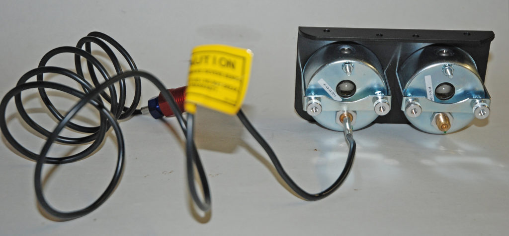
Plumbing and wiring the respective instruments is important too. While the respective gauges all have similarities when it comes to installation, each has its own nuances. For example, the fuel pressure gauge should be plumbed with metallic lines. The same applies to the oil pressure gauge. By the way, most race sanctioning bodies mandate the use of metallic lines for pressure gauges. (Image/Wayne Scraba)
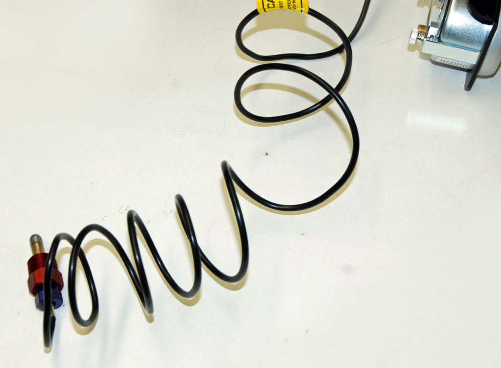
Plumbing a mechanical water temperature gauge is basic, but you should remember that the capillary tube could be kinked or otherwise damaged during installation. If you damage the tube, you’re forced to send the gauge back to the manufacturer for repairs. None-the-less, the basic temperature probe should be located in the water jacket (some people prefer an intake manifold water cross-over for the probe location, while others prefer to install the probe directly into a cylinder head). (Image/Wayne Scraba)
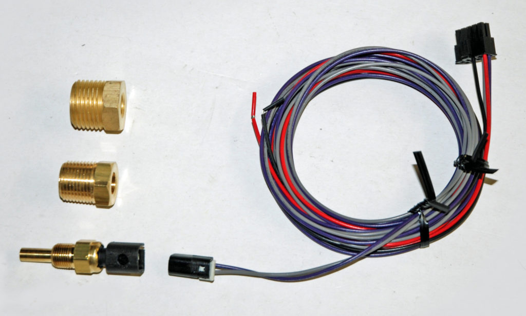
Even with all of the technology and the complex sounding name, electric stepper motor gauges such as this Auto Meter water temperature example are super easy to hook up. The transducer is mounted in the engine (cylinder head or intake manifold water cross-over), using the Auto Meter-supplied adapters. Next, a plug and play wiring harness hooks between the back of the gauge face and the transducer. The black loose wire in the harness goes to an engine ground. The red wire goes to a fused ignition switch. The white wire on the gauge lamp is spliced into the dash lights and the black wire on the gauge lamp goes to ground. Wiring on all of the other gauge lamps is the same too. (Image/Wayne Scraba)
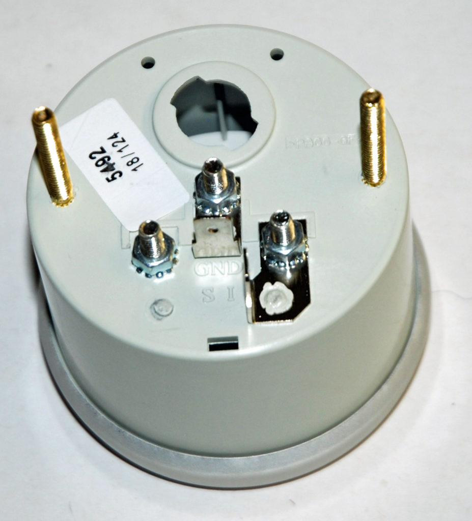
Wiring a voltmeter is basic: One length of wire should run from the positive (+) post on the gauge to a good 12 Volt source (the “hot” side of the ignition switch is a good example). Meanwhile, the negative (-) post on the gauge should be connected to a good chassis ground. Hook the white light wire to the instrument panel lamps and ground the light by running a wire from one of the gauge case mount studs to a good ground. The lamp ground is only required if the instrument panel isn’t properly grounded. (Image/Wayne Scraba)
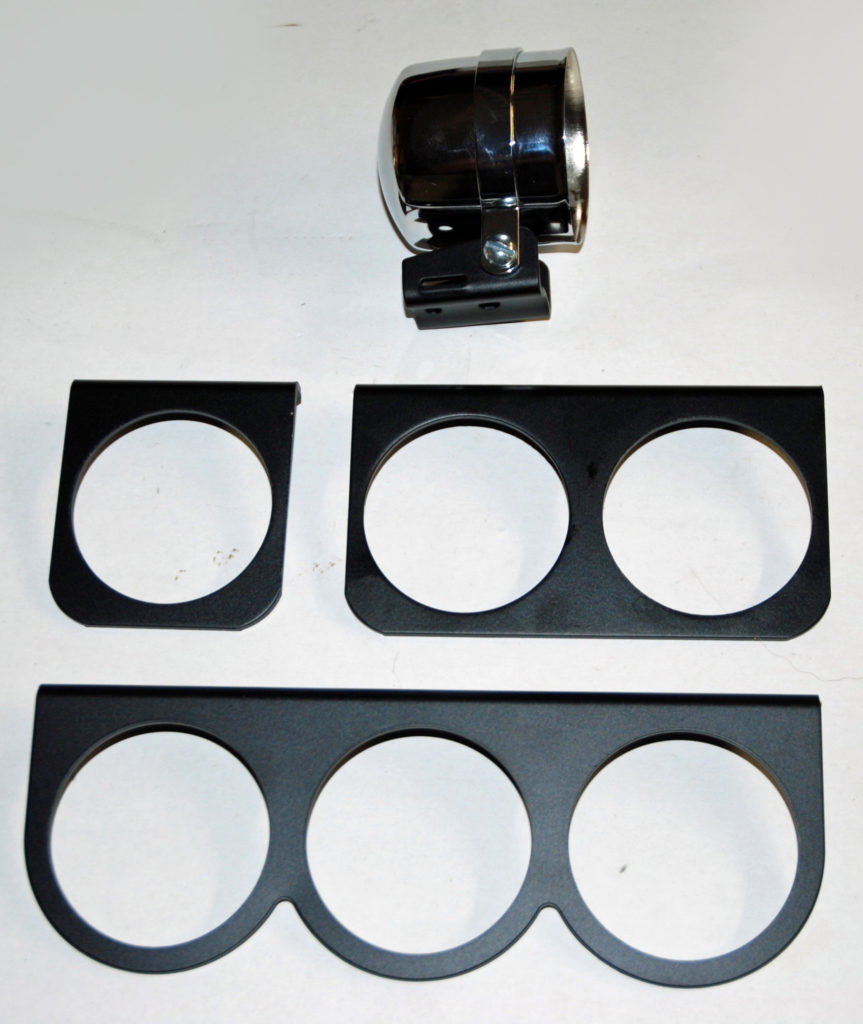
You have all sorts of options when it comes to gauge mounts and installation accessories. Obviously, you can buy single, double and triple gauge brackets. Or you can mount the gauges in cups or even special pillar post pods. (Image/Wayne Scraba)
Wayne, As always I looked through the complete article about gauges and if you do not read you can not learn very much, I wanted to thank you for the information. My driving days are in the past but still a car guy, and very involved in what I do with racing today.
Thanks Bob. For those who don’t know, Mr. Kaiser won the NHRA Competition Eliminator World Championship in 1989 as a team owner and driver and then again in 1992 as the car owner (Steve Johns was the driver). Back then, Competition Eliminator was incredibly fast paced and furious!
Yes you right about gauges oil pressure drop temp run hot voltage drop and running msd burn that system not cheap
Hi I’m not sure how old this post is but I stubbles upon these photos on google images. My brother and I bought a Nissan Silvia with a pro comp auto meter boost gauge. The oil level is like yours in the photo, as in it doesn’t look full. We figured it had a leak and may not be suitable for reuse.
Is it normal for them to be like that?
I’d love to hear back from you. I can supply a photo as well. Thank you in advance.
Thank You for a very informative read. In fact it’s been one of my concerns on my 2007 F-150 XL PU. Is there an electronic full range dash guage replacement for the stock instrument gages(oil pressure & water temperature, single position type) that that actually show low or high oil pres. & Water temp. from sixty to two hundred twelve with sending units to attach to engine?