We’ve built and tuned so many supercharged engines over the years, we’ve lost count. And every time we build a Roots-blown engine, the thing we least look forward to is setting up the carburetor linkage.
If the engine is running a single carb, it’s an easy job. Dual carbs mounted inline is almost as easy. But when we’re talking about side-mounted double pumpers, getting the carb linkage set up properly can be difficult and frustrating.
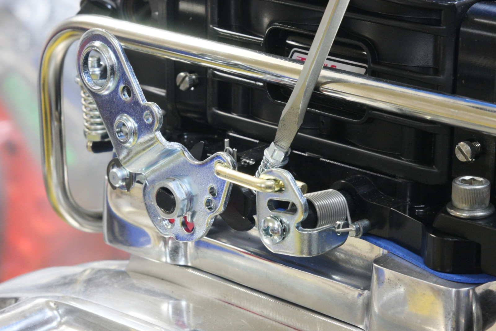
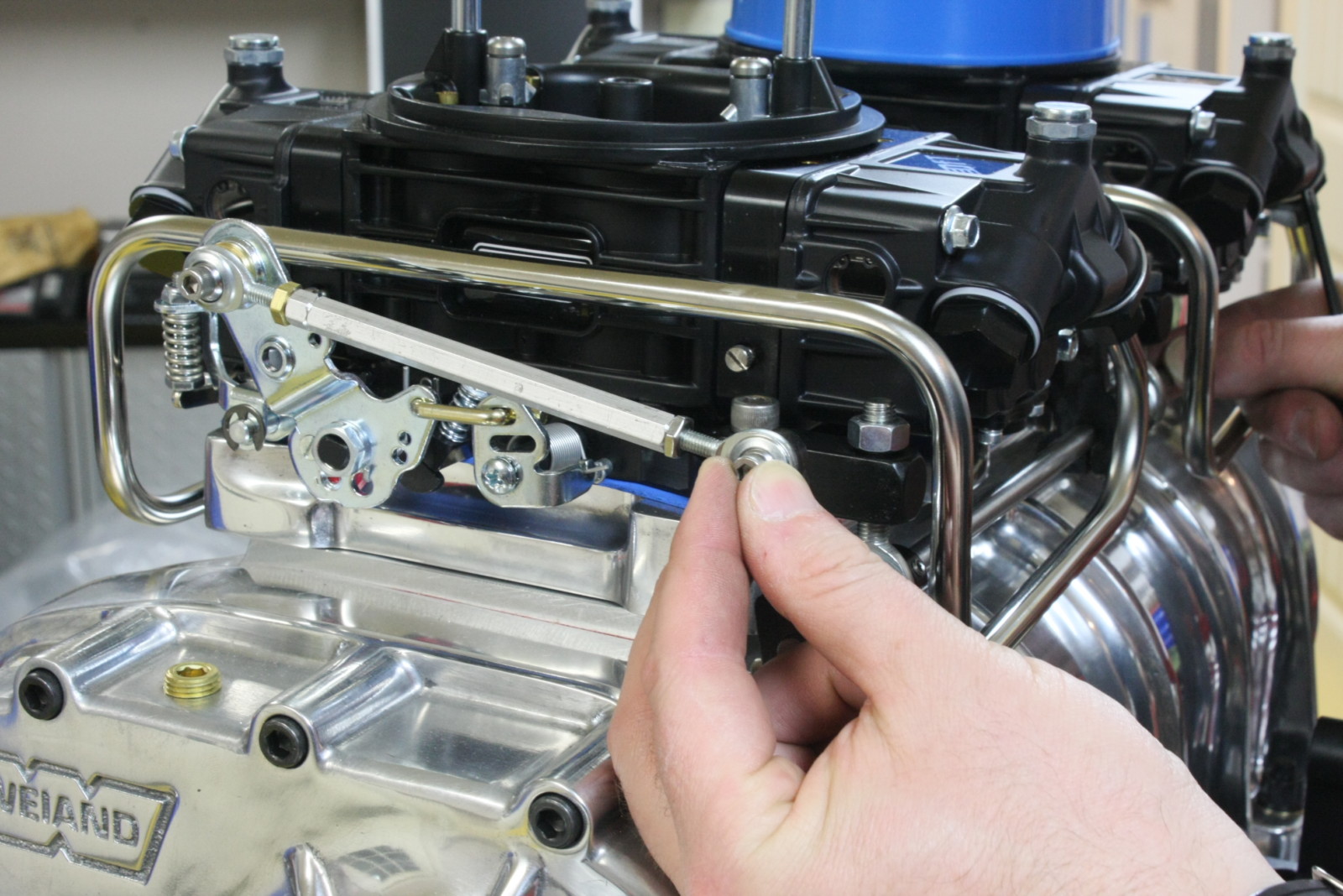
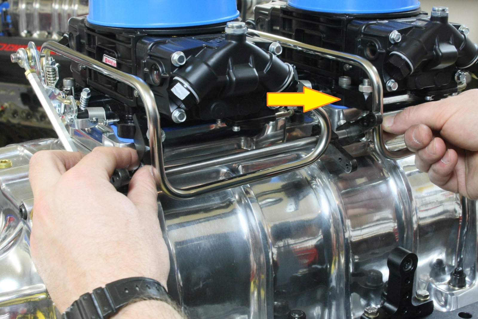
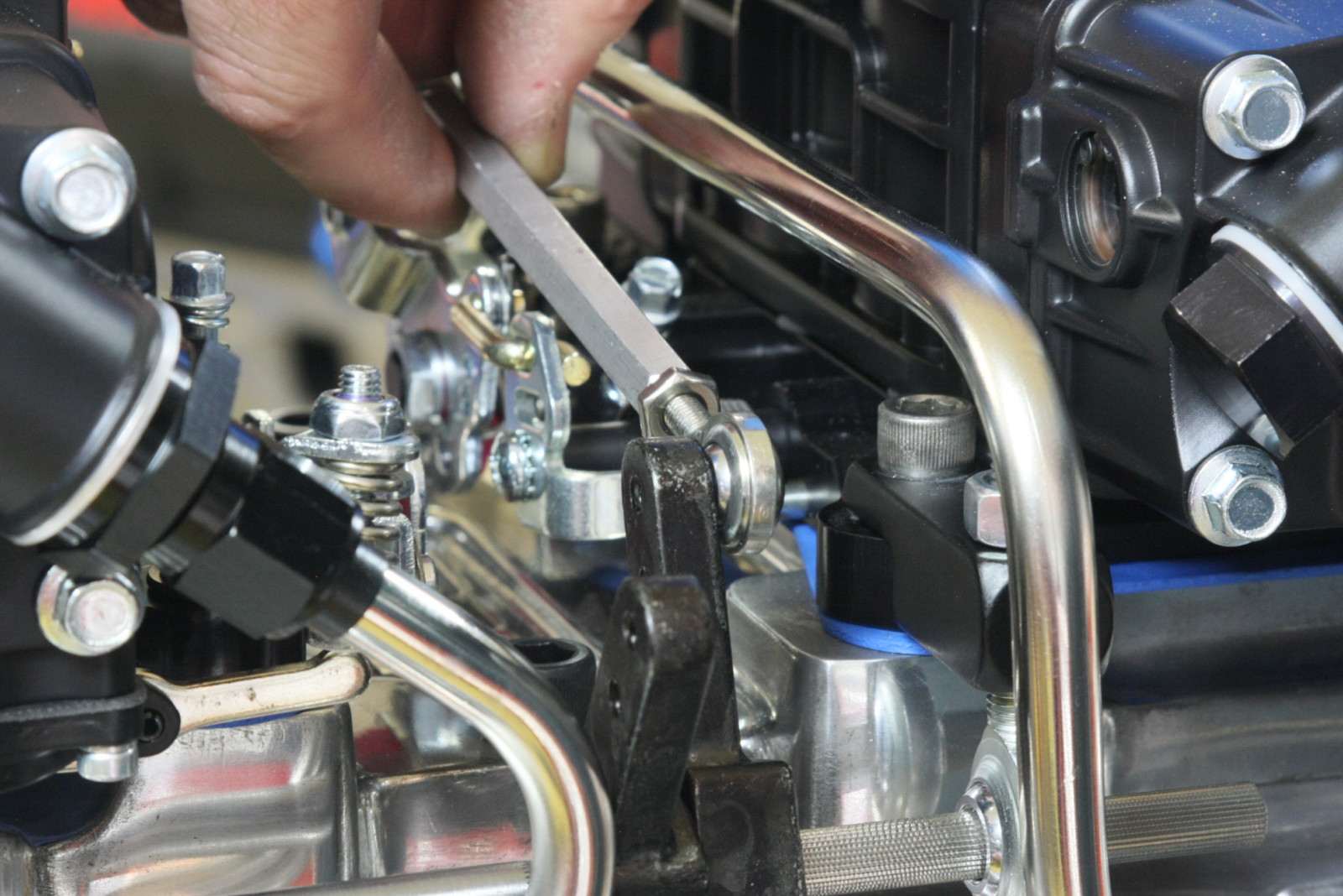
This is the carburetor setup that works best on blown engines. The double pumpers also look the coolest sticking through your hood with all of the rod ends, stainless bolts, fuel pump to carburetor lines and anodized tube nuts running around the top of the blower.
But setting all of that up isn’t fun.
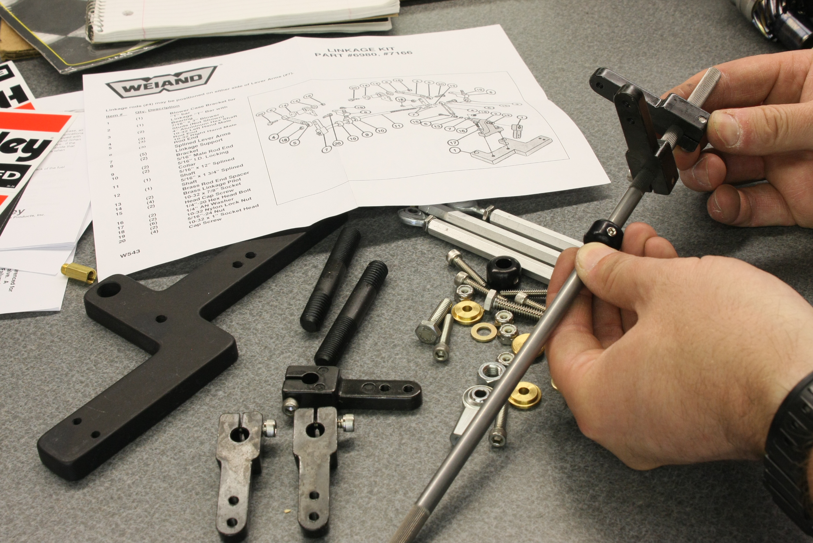
The blower manufacturers don’t always help much either. The instructions they send with the linkage kits usually just include a parts list, a photo of the linkage setup on a blower, and maybe an exploded diagram showing how all the pieces go together. But that’s only marginally helpful, especially if you’ve never done this before.
Over the years, we’ve discovered some tips and tricks that will increase your chances of setting up carburetor linkage right the first time—and maybe help you actually enjoy the process.
Here’s a Step-by-Step Guide to Make Dual Carb Linkage Assembly a Better DIY Experience
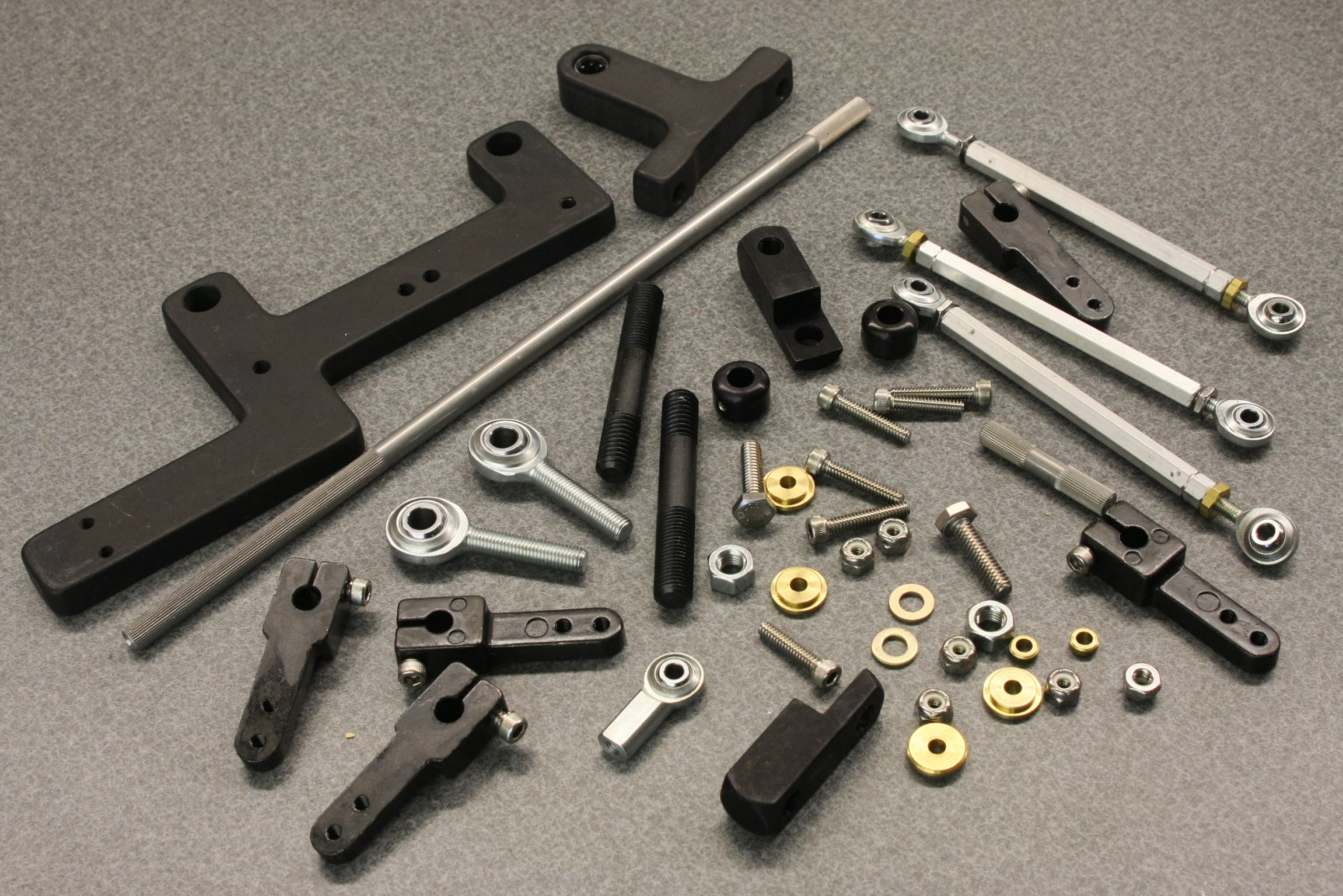
First, take a look at this Weiand 7166-6980 Supercharger Carb Linkage document (printing it out might help) for an exploded view of the parts (there are several!) as well as what proper assembly looks like.
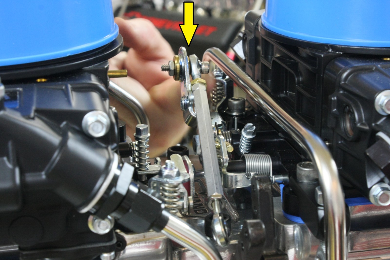
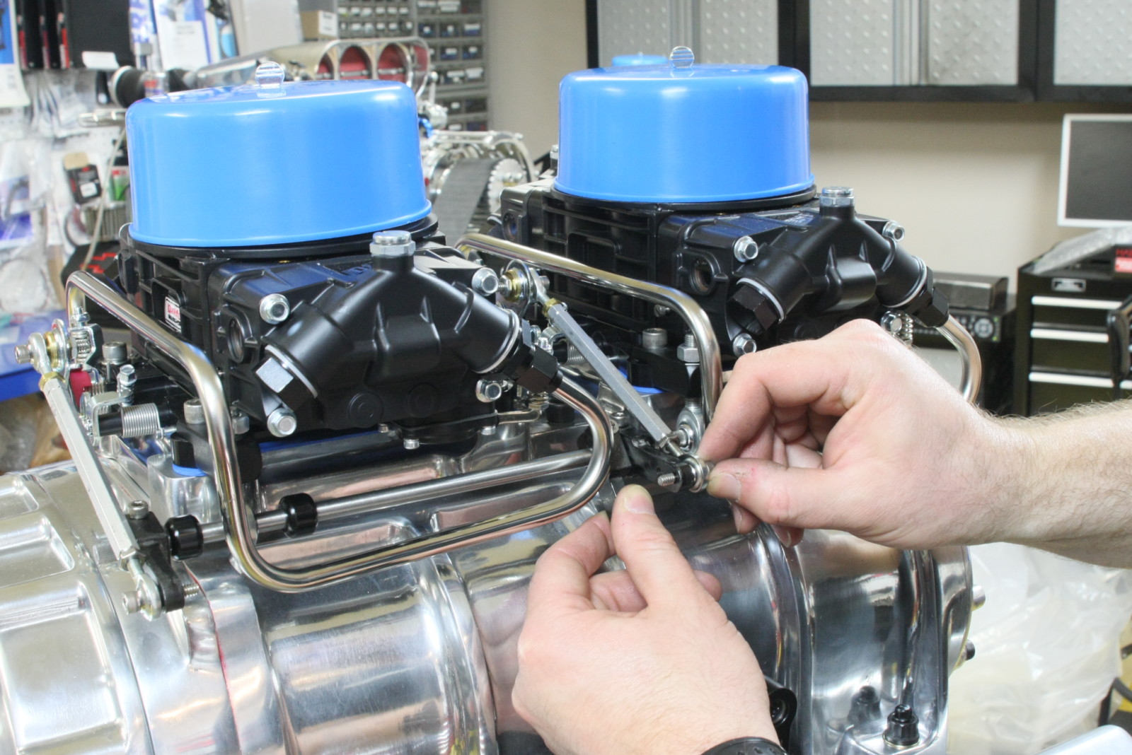
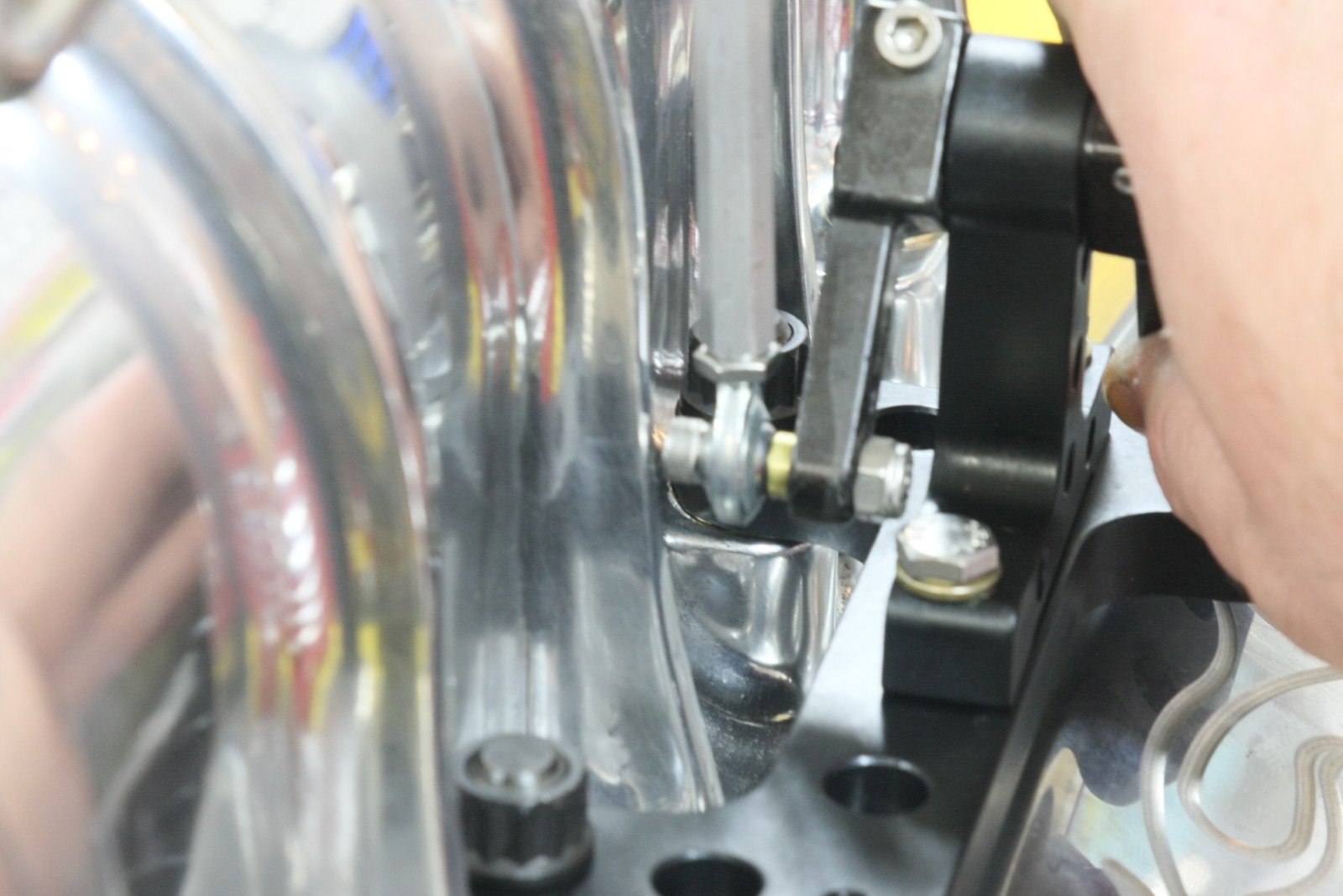
Then, flip through the slideshow photos below to see and read step-by-step instructions for taking the frustration out of assembling dual carb linkage.


That was a Great Report… But; My (2) Carb units are: Ram Log 2 small Hollys ( 429) Ford… & (2) Webbers 44’s 0n Log, Port / Cyl 2300 Pinto…Pictures available.
I’m modeling a high rise with dual carb set up as above. This is a detail gold mine! Workings are very well explained and the photos are priceless. Nice job all around. Now to fabricate the linkage in 1/25 scale. Great post!
where i can get the carbs linkage assembly
At the blower shop.
I have this same linkage on my 8:71 blower with 2 side saddled 800 Holley double pumpers. My issue is no matter how I play with the linkage adjustment when I press my gas pedal to the floor the secondarys dont open all the way. I have a 69 Nova with a BB. Im thinking my stock gas pedal isnt giving enough throw? Im looking into a lokar gas pedal with an adjustable arm. I have a cable and not the stock throttle rod linkage, what is your opinion on my situation? Any help would be appreciated.
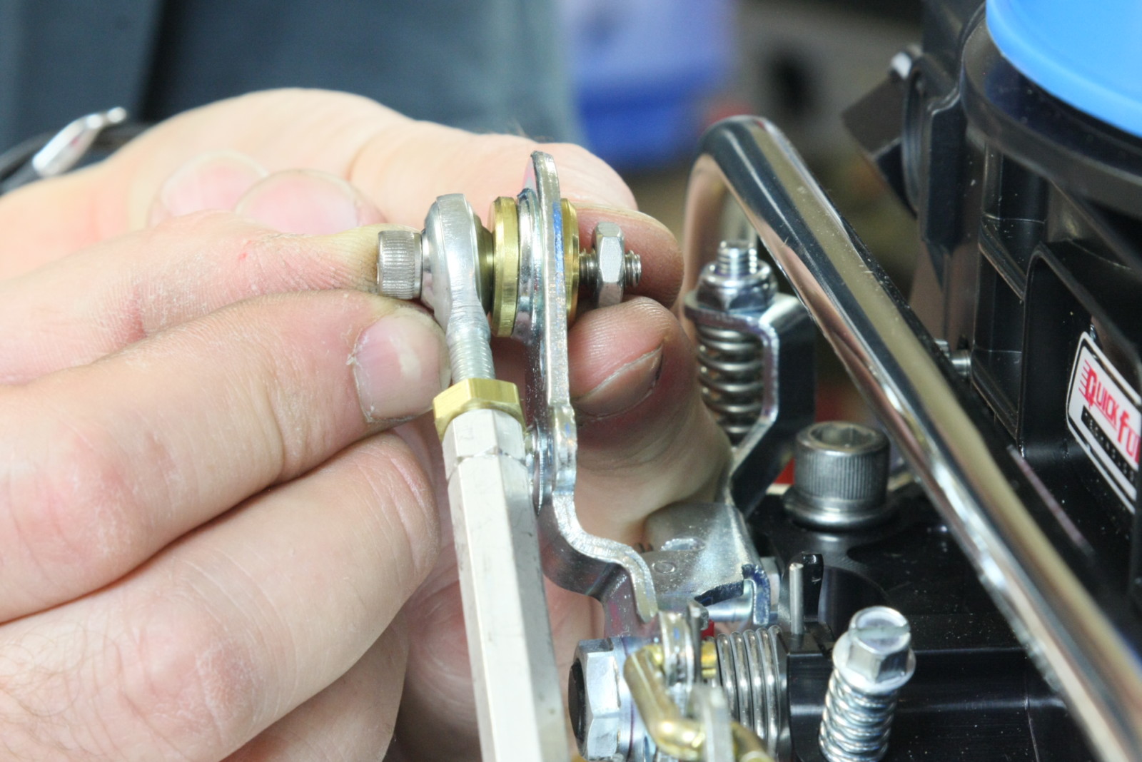
WHY on pic #21 is the rod end on the back side of the carb lever?Mine is setup the “wrong way” and have never had problems.Guess I am looking for an explanation as to why this emphasized…
I’m trying to setup dual edelbrock 1405 carbs. Have no idea how to set up linkage. Any help would be appreciated. Thanks
I have the same linkage on a 671 Weiand blower with carbs set sideways. Trying to figure out how to mount kickdown cable for 700cr transmission. Any thoughts?
Is an additional return spring necessary ?
Hey Tony, thanks for reading–Throttle linkage security and safety is really important; an extra return spring is a smart backup that minimizes the risk of a runaway engine.