Your metal automotive fasteners can fail one of six ways.
And, according to our friends ARP—an industry leader in fastener technology—each type of metallurgical failure has a unique, identifiable characteristic. And by carefully inspecting failed fastener, and correctly diagnosing the reason for their failure, you can take steps to ensure it won’t happen again.
ARP created a visual aid, using close-up images of failed fasteners and explaining the observable physical characters of each. It’s a guide designed to be used like you would a spark plug reading chart.
About 98 percent of failed fasteners can be diagnosed with a simple three-lens magnifying glass, ARP says.
Here are ARP’s tips for recognizing common fastener failures:
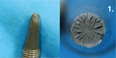
1. Typical Tensile Overload
Image/ARP
“In a tensile overload failure, the bolt will stretch and ‘neck down’ prior to rupture. One of the fracture faces will form a cup and the other a cone. This type of failure indicates that either the bolt was inadequate for the installation or it was preloaded beyond the material’s yield point.”
2. Torsional Shear (Twisting)
Image/ARP
“Fasteners are not normally subjected to torsional stress. This sort of failure is usually seen in driveshafts, input shafts and output shafts. However we have seen torsional shear failure when galling takes place between the male and female threads (always due to using the wrong lubricant or no lubricant) or when the male fastener is misaligned with the female thread. The direction of failure is obvious and, in most cases, failure occurs on disassembly.”
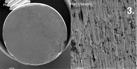
3. Impact Shear
Image/ARP
“Fracture from impact shear is similar in appearance to torsional shear failure with flat failure faces and obvious directional traces. Failures due to impact shear occur in bolts loaded in single shear, like flywheel bolts and ring gear bolts. Usually the failed bolts were called upon to locate the device as well as to clamp it and, almost always, the bolts were insufficiently preloaded on installation. Fasteners are designed to clamp parts together, not to locate them. Location is the function of dowels. Another area where impact failures are common is in connecting rod bolts, when a catastrophic failure, elsewhere in the engine (debris from failing camshaft or crankshaft) impacts the connecting rod.”
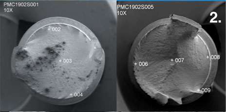
4. Cyclic Fatigue Failure Originated by Hydrogen Embrittlement

Image/ARP
“Some of the high strength ‘quench and temper’ steel alloys used in fastener manufacture are subject to ‘hydrogen embrittlement.’ L-19®, H-11, 300M, Aeromet and other similar alloys popular in drag racing, are particularly susceptible and extreme care must be exercised in manufacture. The spot on the first photo is typical of the origin of this type of failure. The second is an SEM photo at 30X magnification.”
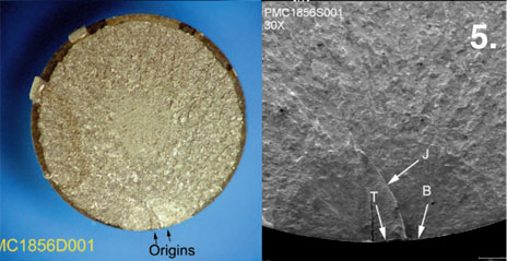
5. Cyclic Fatigue Cracks Propagated from a Rust Pit (Stress Corrosion)
Image/ARP
“Again, many of the high strength steel alloys are susceptible to stress corrosion. The photos illustrate such a failure. The first picture is a digital photo with an arrow pointing to the double origin of the fatigue cracks. The second photograph at 30X magnification shows a third arrow pointing to the juncture of the cracks propagating from the rust pits. L-19, H-11, 300M and Aeromet, are particularly susceptible to stress corrosion and must be kept well oiled and never exposed to moisture including sweat. Inconel 718, ARP 3.5 and Custom age 625+ are immune to both hydrogen embrittlement and stress corrosion.”
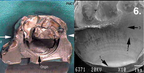
6. Cyclic Fatigue Cracks Initiated by Improper Installation Preload
Image/ARP
“Many connecting rod bolt failures are caused by insufficient preload. When a fastener is insufficiently preloaded during installation the dynamic load may exceed the clamping load resulting in cyclic tensile stress and eventual failure. The first picture is a digital photo of such a failure with the bolt still in the rod. The arrows indicate the location of a cut made to free the bolt. The third arrow shows the origin of the fatigue crack in the second picture – an SEM photo at 30X magnification that clearly shows the origin of the failure (1), and the telltale ‘thumbprint’ or ‘beach mark’ (2). Finally (3) tracks of the outwardly propagating fatigue cracks, and the point where the bolt (unable to carry any further load) breaks-away.”
[…] I don't think that's all he sees, but I sure hope it's a part of what he sees. Also, I'm sure that the cap had been brutalized on and off many times before you ever saw it. That's a typical result of torsional stress. These: ReliabilityWeb.com: Preventing Mechanical Failures -* An Introduction to Failure Mode Identification Root Cause Failure Analysis – Understanding Mechanical Failures How to Diagnose Common Fastener Failures – OnAllCylinders […]
[…] would a rear engine bolt snap? The best I can come up with is hydrogen embrittlement. See #4 here. The issue there is that your bolt should be part of a bad batch, which would likely include the […]
I have a picture of a bolt that I’d like your opinion on why it failed. Interested? Send me your email.
Is it possible to download or print a copy of your fastener failure pictures for reference? I would appreciate any help you can give as my builder doesn’t seem to be able to identify a failure I have had. Thank- you Craig Westedt
Hey Craig, thanks for reading–you can use an online website-to-pdf converter to makes this page a PDF, then download it, print it, email it, whatever.
I have a cam bolt that failed. I took a pix. It would be interesting why it failed. Can I send the picture to you? Thanks!