


If you ever have the chance to discuss engine tuning troubles with the legendary Jon Kaase, you’ll rejoice in his simple logic:
“Most engine troubles are centered on spark or fuel—if it has the former, it is either getting too much or too little of the latter,” Kaase says.
With help from the carburetor experts at Demon Carburetion, we’ll dedicate two posts to helping you select and tune the right carburetor for your application and performance aspirations. In this first part, we’ll compare vacuum secondary-style carburetors with mechanical secondary models, explore the reasons for increasing the initial ignition timing, and examine the essentials of a modular carburetor’s metering block.
In Carb Tuning Tips, Part 2, we’ll talk about the importance of vacuum to your engine’s power production and how the carburetor plays a role. We’ll on the fundamentals of tuning, including opportunities and potential problems with the idle circuit, float levels, accelerator pump shooters (nozzles), and air bleeds.
According to Demon Carburetion, it’s important to start by doing a little myth busting.
Selecting Carb Size by Formula: Debunking the Myth
Formulas have abounded for years and sometimes they work—but occasionally they don’t. One of the most common formulas states that you multiply your CID (cubic inch displacement) by your maximum rpm and divide that figure by 3456.
For example, if you owned a mildly tuned 400 cubic-inch street engine that turned 6,500 rpm, the formula would suggest a carburetor size of 750 cfm (cubic feet per minute). However, if the cam duration was rated at less than 210 degrees @ .050-inch valve lift, this recommendation would be suspect. In this case, the most probable outcome would be lazy, uninspired performance influenced by slow air speed and an overly rich condition at low engine speeds. Demon Carburetion would recommend 525 cfm, or 625 cfm at the most, in this situation.
The moral of the story: Formulas may get you in the right ballpark for carburetor size, but when in doubt, it pays to speak to the carburetor manufacturer about sizing.
Secondary Throttles: Vacuum or Mechanical
Vacuum secondary carburetors are commonly used on mildly and moderately tuned street cars with automatic transmissions. Compared with mechanical secondary carburetors, they are more forgiving in operation. This is largely because the function of the secondary throttles is controlled by air speed and engine load. For example, if the motor isn’t producing sufficient air speed or if the vacuum secondary carburetor selected is too large for its application—and as a result the secondary throttles don’t open fully—any loss in performance will be barely discernible.
In contrast, mechanical secondary carburetors must be tuned precisely. When tuned to their best potential and used on lighter, high-revving street cars with radical camshafts and low gearing or race applications with manual transmissions (or automatics with stall speeds in excess of 3,000 rpm), they make more power. This is because the mechanical linkage connected to the secondary throttles is geared to respond almost instantly. Still, carburetors with mechanically operated secondary throttles are sensitive to sizing and tuning disciplines. Select the wrong size for your application or use incorrect tuning, and the mechanical secondary throttles could reward you with disheartening hesitation under rapid acceleration.
Whether mechanical or vacuum operated, the tuning procedures are similar on both carburetors. The only main difference is opening rate of the secondary throttles can be hastened or retarded by spring changes.
The Importance of Initial Ignition Timing
Incorrect timing has condemned the carburetor’s reputation more than most could imagine. Yet ignition timing is determined more by the engine combination than by the carburetor. Bigger camshafts and/or larger cylinder heads with matched intake manifolds require increased ignition timing to promote better air velocity and maintain efficiency. Thus, the carburetor is helpless if the initial timing is late or the timing advance curve is slow.
These two potential timing impediments frequently exhibit poorer starting and drivability troubles, which are manifested by rich idle, or hesitations, or the engine dying when engaging gear, or when decelerating to a stop. When carburetor or drivability complications occur under 3,000 rpm, improper timing is usually contributing to it.
Currently, magazines are carrying an abundance of advice on re-timing the advance curve, but curiously little is said about increasing the initial timing. Ten years ago, Demon Carburetion published helpful recommendations on this topic. Based on engine displacement and camshaft duration at .050 inches of valve lift, their initial timing statistics are still effective today.
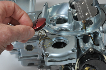
Metering Blocks
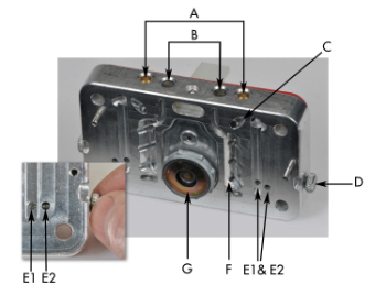
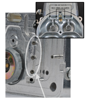
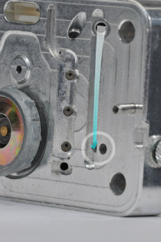
The metering blocks, which feature four vertical fuel wells—two main wells and two idle wells—meter fuel and mix it with air. The idle wells receive their fuel supply from the main wells via a small transfer port at the bottom of each main well. The main well fuel is metered by the main jets which have direct access to the fuel bowls. The idle well fuel is metered by the idle-feed restrictors, which can be placed either at the bottom or the top of the idle wells.
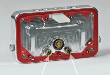
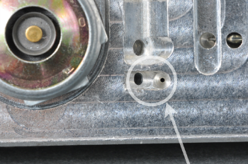
Air is metered by the idle air bleeds and by the high-speed air bleeds placed in the carburetor’s main air entries. Through these tiny air bleeds, the precisely metered air is introduced to their respective fuel wells and mixed with the fuel (emulsified). The metering block pictured in this article shows three emulsion holes in each main well. The vacuum sensed at the boost venturii draws the emulsified air/fuel mixture up and out of the main wells at high speed and into the carburetor’s four barrels, where the fast moving air stream atomizes it (separates it into small particles) and whisks it down through the intake manifold and into the engine cylinders below.
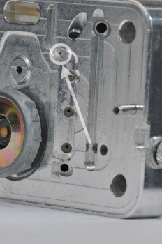
The fuel in the idle circuits flows almost two inches upward and then turns through a 180-degree bend at the top of the metering block where it is introduced to its source of air. The flow continues downward through the transfer slot and idle-fuel passageways where it discharges from the base plate into the carburetor’s four barrels. The idle discharge ports are placed below the throttle blades; the transfer slots are carefully concealed behind the throttle blades when they are in the almost closed idle position.
Carb Tuning Overview
The first step of carburetor tuning entails checking the performance of the idle circuits, which we’ll talk about in part two of this post. The procedure includes setting the idle speed and the idle mixture while ensuring the transfer slots are not overexposed when in the idle condition. A common error in idle tuning occurs when main jets are inappropriately removed and replaced by smaller ones to correct a rich idle. A rich idle condition would normally be corrected by the idle-mixture adjustment procedure.
Main jets are used to tune an engine to produce its best top-end power. Unless you have access to a dynamometer and can reliably observe changes in the fuel curve, the traditional trial-and-error method is still regarded as the most successful technique. If top-end power improves by increasing main jet sizes by two steps, continue in that direction until the improvements have stopped. Then return to the jetting that worked best.
Commonly, people leave power valve tuning alone, preferring instead to gain their throttle-response advantages by dialing in the accelerator pump. Still, it’s helpful to know the power valve’s function.
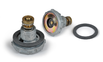
Power valves are used chiefly to improve drivability. Operated by engine vacuum and rated in inches of mercury (in/Hg), the power valve remains closed during periods of high vacuum (idle and part-throttle). But when engine vacuum diminishes (under hard throttling) they open and deliver an additional source of fuel to the carburetor’s main wells. By opening and closing in this way they keep the carburetion crisper and the combustion process cleaner. Depending upon the application, throttle response improves, both under aggressive acceleration, sharp deceleration, and hard braking.
One power valve is often found in four-barrel modular carburetors of street cars whereas oval track and road race cars are often equipped with two. Generally, drag race cars don’t use any as their sole function is devoted to full-throttle motoring and drivability is of little consequence.
Power valves, which should be rated at least 1.5in/Hg below idle vacuum, are situated above and between the main jets. They have direct access to the fuel bowl and deliver their fuel through channel restrictors into the lower regions of the main wells. Their source of vacuum originates at the base plate.
When disabling a power valve circuit, the valve should be replaced by a solid plug and the main jets on the affected metering block increased by 8-10 sizes to compensate for the loss of power-valve fuel flow. Vehicles with automatic transmissions have their idle vacuum checked while in gear.
In Carb Tuning Tips, Part 2, we’ll talk more in-depth about tuning.
Very good article. Details are stated clearly for those familiar w/ the carbs mentioned. Only improvements could be pictures and/or diagrams.
Really good article for me because I’m trying to learn how to tune my carb, only mine is a Holley so I’m not sure how much the stuff about Demon carbs applies to me. Still interesting to read though.
So that’s how you learn all that stuff!
Yep, this site is awesome, I buy everything I can from Summit haha
good article. thanks summit..
very good info on carbs and some of their stange habits. it, s not always just bolt one on.
great articile, explanations are dead on target.
[…] Carb Tuning Tips, Part 1, we provided a brief overview of the carburetor, including some basic carburetor anatomy. In Part […]