You spent a lot of time searching the Internet for the right camshaft for your latest engine project. You drove your friends crazy babbling about intake, duration, and lobe separation, and then you talked the ear off of who knows how many tech guys asking for advice.
So why not spend a little more time making sure your cam delivers all of the power the manufacturer ground into it?
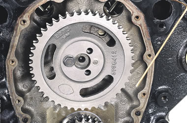
The process is called degreeing. In simple terms, it’s the proper phasing of the camshaft with the crank so the valve opening and closing events occur when the cam designer intended them to. The process is not difficult, especially when you have a tool like the Competition Cams Cam Degree Kit.
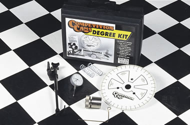
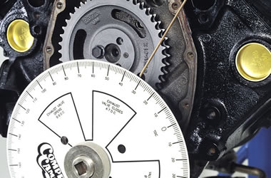
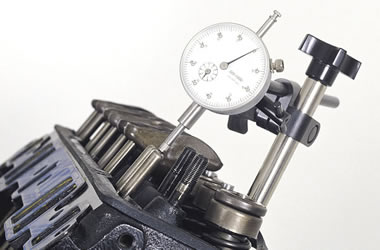
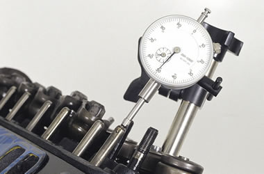
The kit includes everything you need to do the job: nine-inch diameter degree wheel, dial indicator with one inch of travel, adjustable dial indicator stand, adjustable pointer, piston stop, two checking springs, and written instructions, plus a step-by-step instructional video. The kit is also useful for checking things like cam lift and base circle runout, piston-to-valve clearance, cylinder Top
Dead Center, valve lift, and rocker arm ratio.
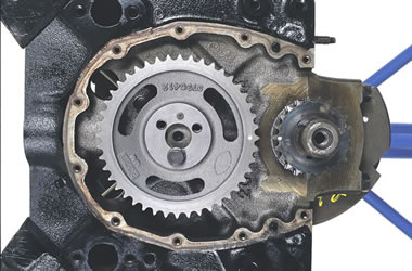
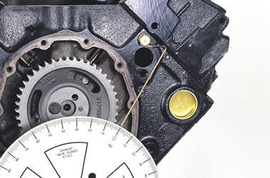
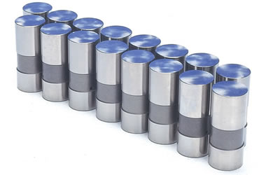
We’re going to show you how to use the cam degree kit to set up a hydraulic cam in a small block Chevy engine. The process is fundamentally the same for all cam and engine types.
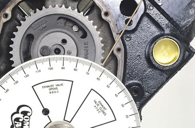
We will be using the intake centerline degreeing method recommended by COMP Cams. This method offers a quick, easy way to advance or retard the cam’s intake centerline, which has the greatest effect on an engine’s performance potential.
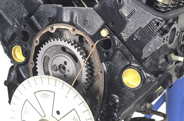
Follow our step-by-step outline in the slide show, and you’ll get a good idea about how easy it is to degree your own camshaft. You can thank us for the extra horsepower later.


Parts List
COMP Cams Cam Degree Kit (CCA-4796)
[…] interested in timing lights, you should also be interested in degree wheels. There are used for degreeing your camshaft, which is easier than you might […]
[…] for head gaskets; however, installing a copper head gasket and O-ring system is really easier than degreeing a cam—and just as […]
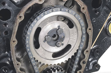
How do you mount it on engine and what precautions do take
Not too much to it! Here’s a video with some additional information focusing on the degree wheel installation: https://www.youtube.com/watch?v=XKtsHqHDX2A
Thank you for this https://www.onallcylinders.com/2012/02/06/how-to-degree-your-camshaft/ post, and youtube link too!
Very useful information. Thanks!