See all the articles in this Back in Black Nighthawk LS series here:
We recently were commissioned to build a street performance engine for AERA (Automotive Engine Rebuilders Association) to display at the 2015 Performance Racing Industry trade show in Indianapolis. We decided to build a 408 cubic inch LS engine with the goal of making around 600 horsepower.
The build is based on a GM cast iron 6.0L OE block. Basic specs are:
- Bore: 4.030 inch
- Stroke: 4.000 inch
- Rod Length: 6.125 inch
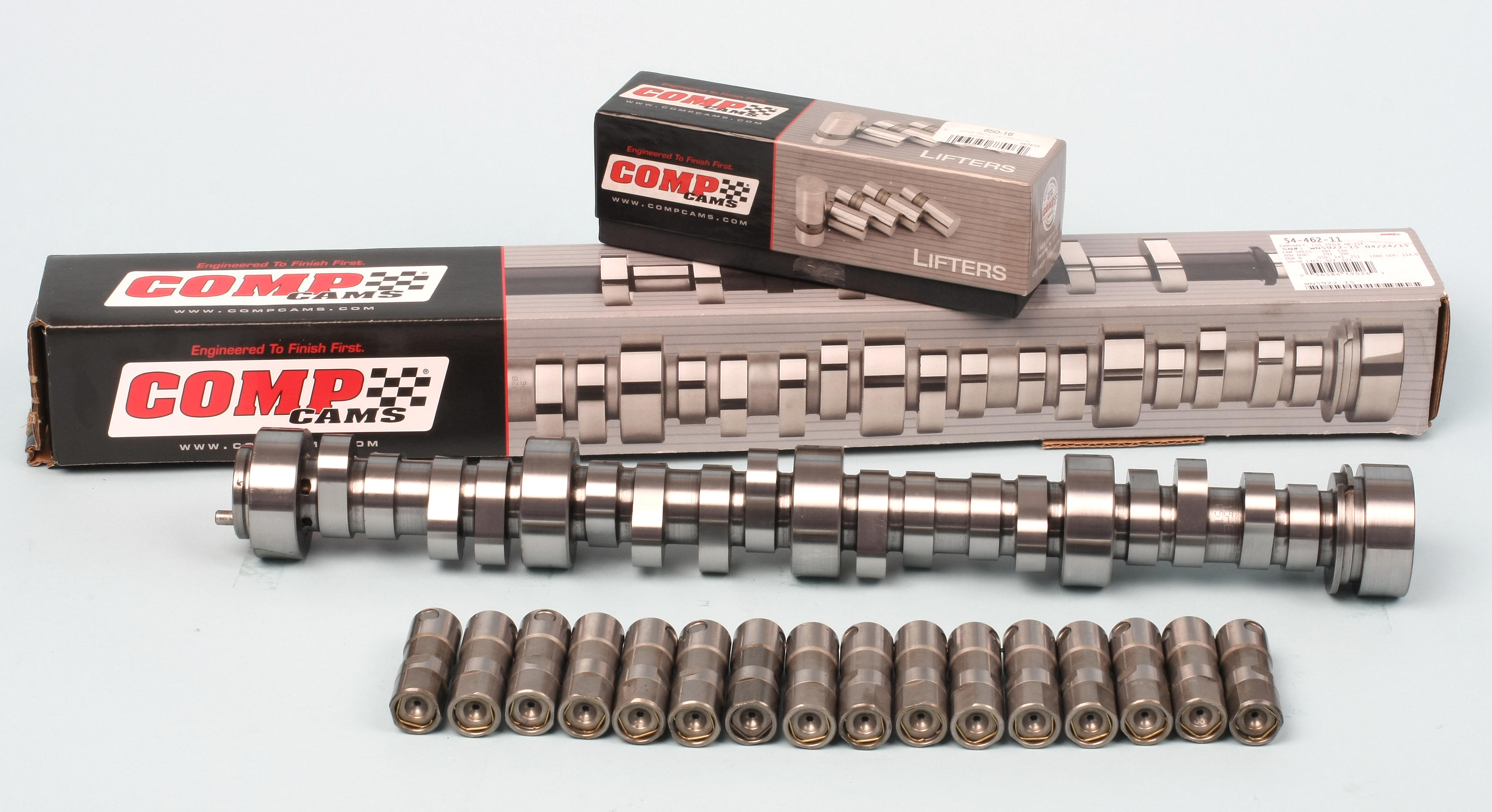
- Camshaft: 0.624 inch intake/exhaust lift, 243/251 degree duration @.050, 114 degree lobe separation
- Cylinder Heads: Aluminum with 225cc intake runners and 65cc combustion chambers
- Compression with .051 inch thick head gasket: 11.44:1
After lengthy deliberation, we decided to go with an all-black theme with ARP polished stainless fasteners, red MSD ignition coils, and red MSD ignition wires for some contrast. contrasts included a selection of ARP polished stainless steel 12 point fasteners, red MSD coils and red plug wires. This black-out theme is sometimes referred to as a “murdered” color scheme (probably referring to a flock of crows, known in the bird world as a “murder of crows”). Thus, the name Nighthawk LS.
Block Prep
Our 6.0L block is used, so there was some prep work to do before machining. Whether dealing with a used or new block, never assume the threaded holes are clean. All threads should be verified for condition and cleanliness.
Instead of using a conventional cutting tap which could remove material, we used cleaning taps designed to follow and reform and clean threads. We used ARP cleaning taps in the following sizes:
- 11mm x 2.0 for head bolt holes in the block
- 8mm x 1.25 for front and rear covers, top cover, and other areas
- 6mm x 1.0 for locations such as the oil pickup tube moun
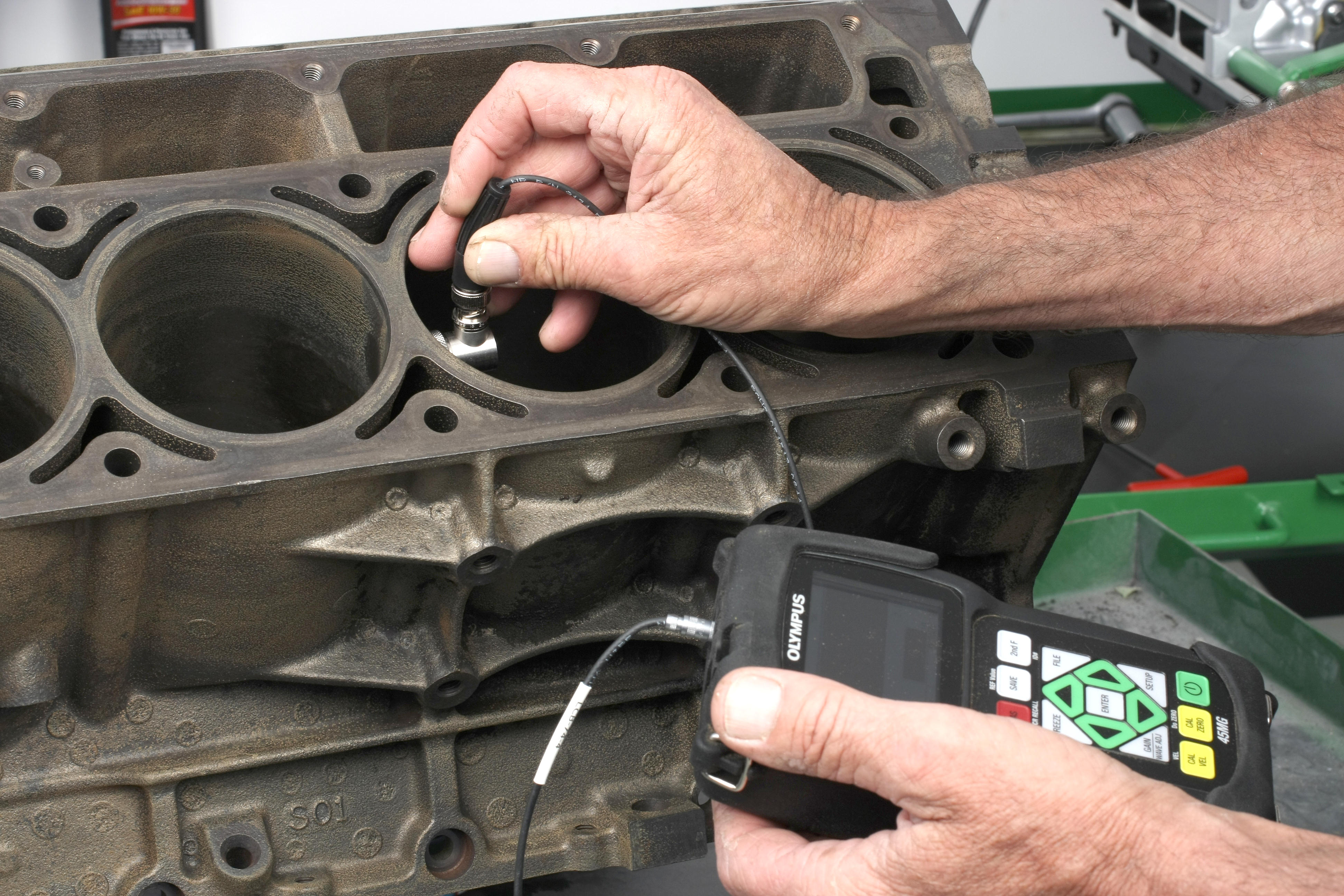
We thoroughly washed and degreased the block, followed by a mag check and a sonic check for cylinder wall thickness. Performing a sonic check helps determine if the block has dangerously thin walls or if there was severe core shift during the casting process. Our cylinders averaged 0.288 inch on the major thrust sides and 0.284 inch on the minor thrust sides.
Many tedious hours were spent smoothing out the block exterior, eliminating casting flashings, burrs, casting imperfections, etc. It took gobs of Scotchbrite pads and small milling bits on a pneumatic die grinder.
Block Machining
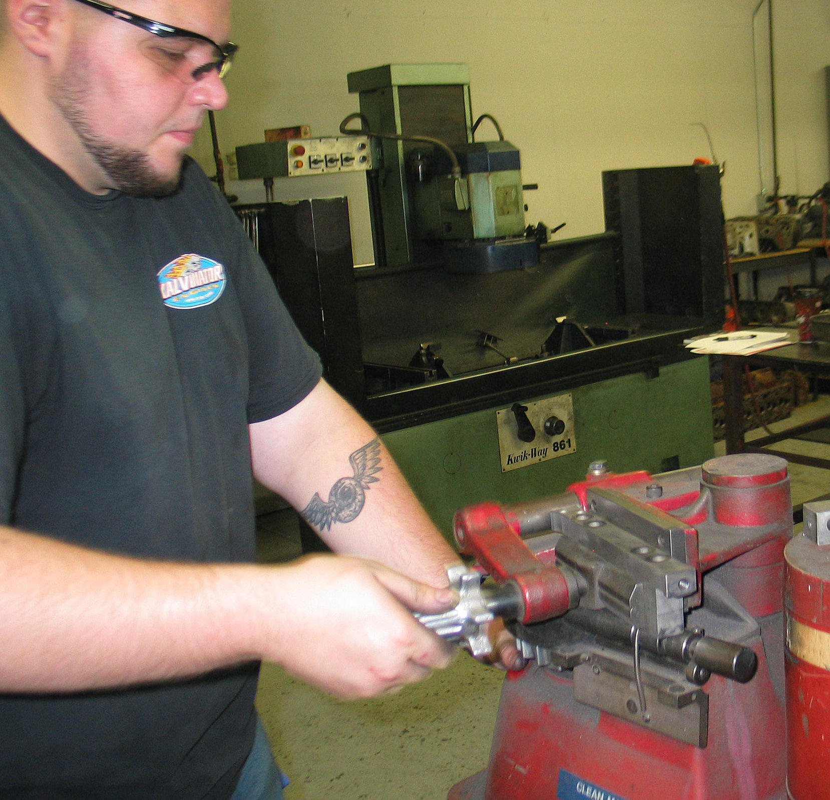
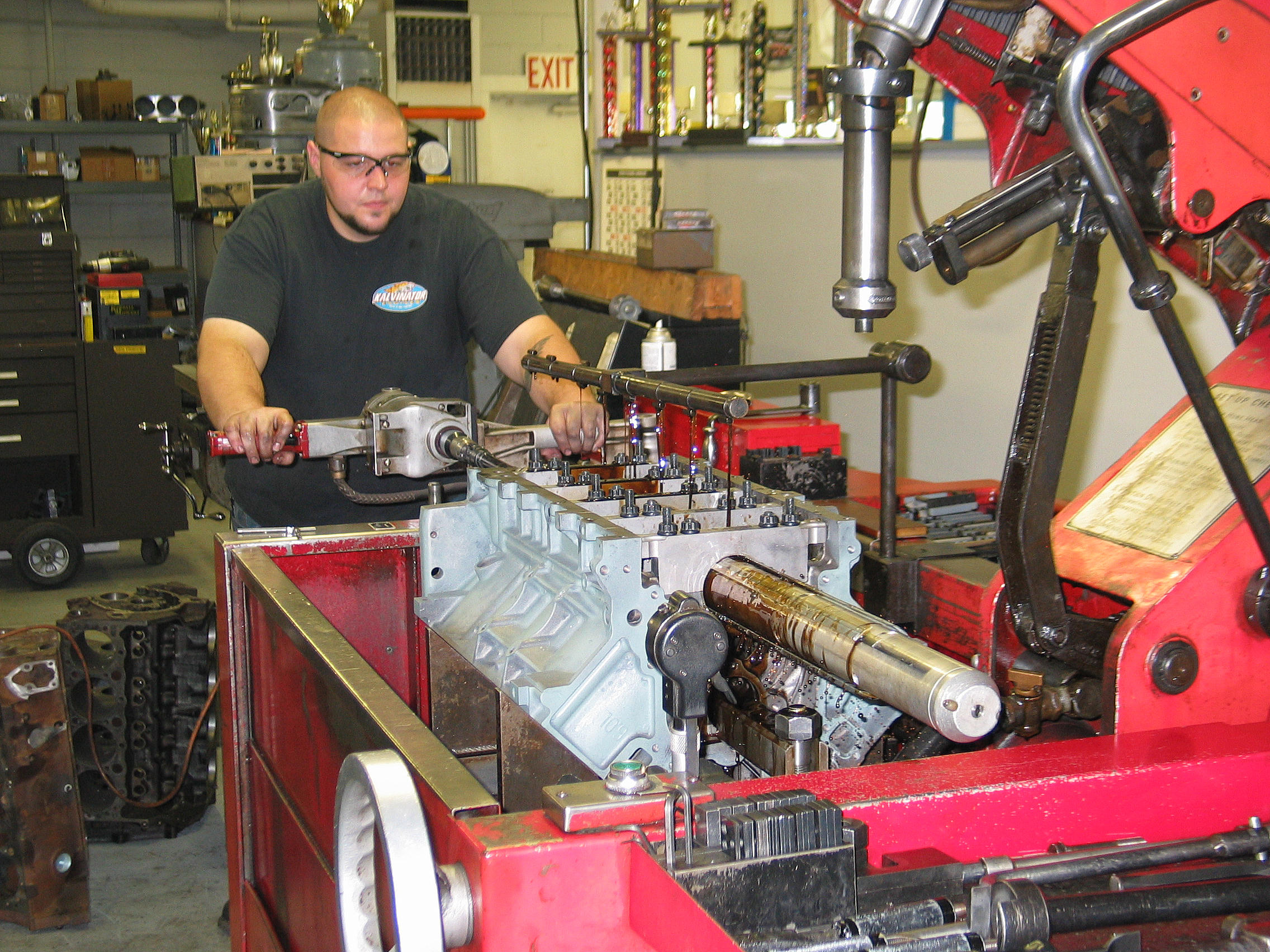
Block machining was entrusted to Kevin Frische’s Kalvinator Engines shop in Wapakoneta, OH. Kevin’s son Justin did the block work.
The main bores were checked for dimension and alignment with the main caps fully torqued in place. All five bores were found to be slightly oversize and out of round. To correct the problem, 0.003 inch was shaved off the main caps to obtain a 0.001 inch undersize bore. The main bores were then align honed to 2.750 to 2.751 inch. GM’s block design features 8mm side “inch” bolts that allow main cap height to be reduced by approximately 0.010 inch if needed.
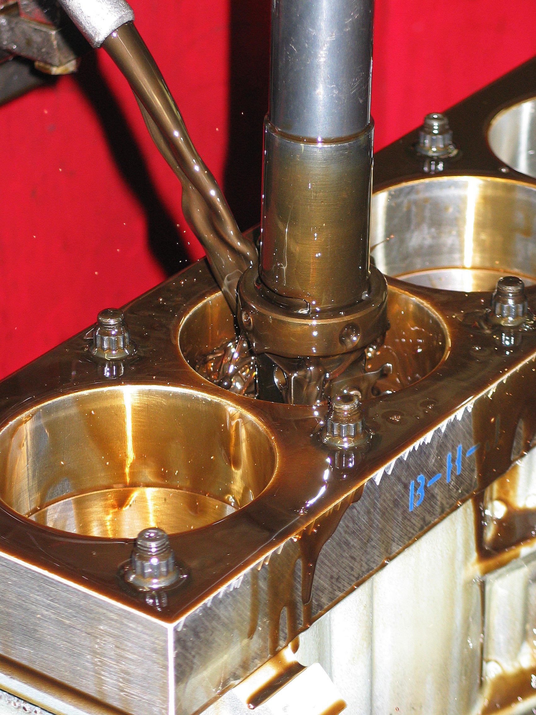
The cylinder bores were roughed in to 4.025 inch and final honed to 4.031 inch inch with BHJ torque plates attached to simulate the bore distortion caused by the cylinder heads. The final hone provided the 0.0045 inch piston-to-wall clearance recommended by Icon Pistons for a naturally aspirated application.
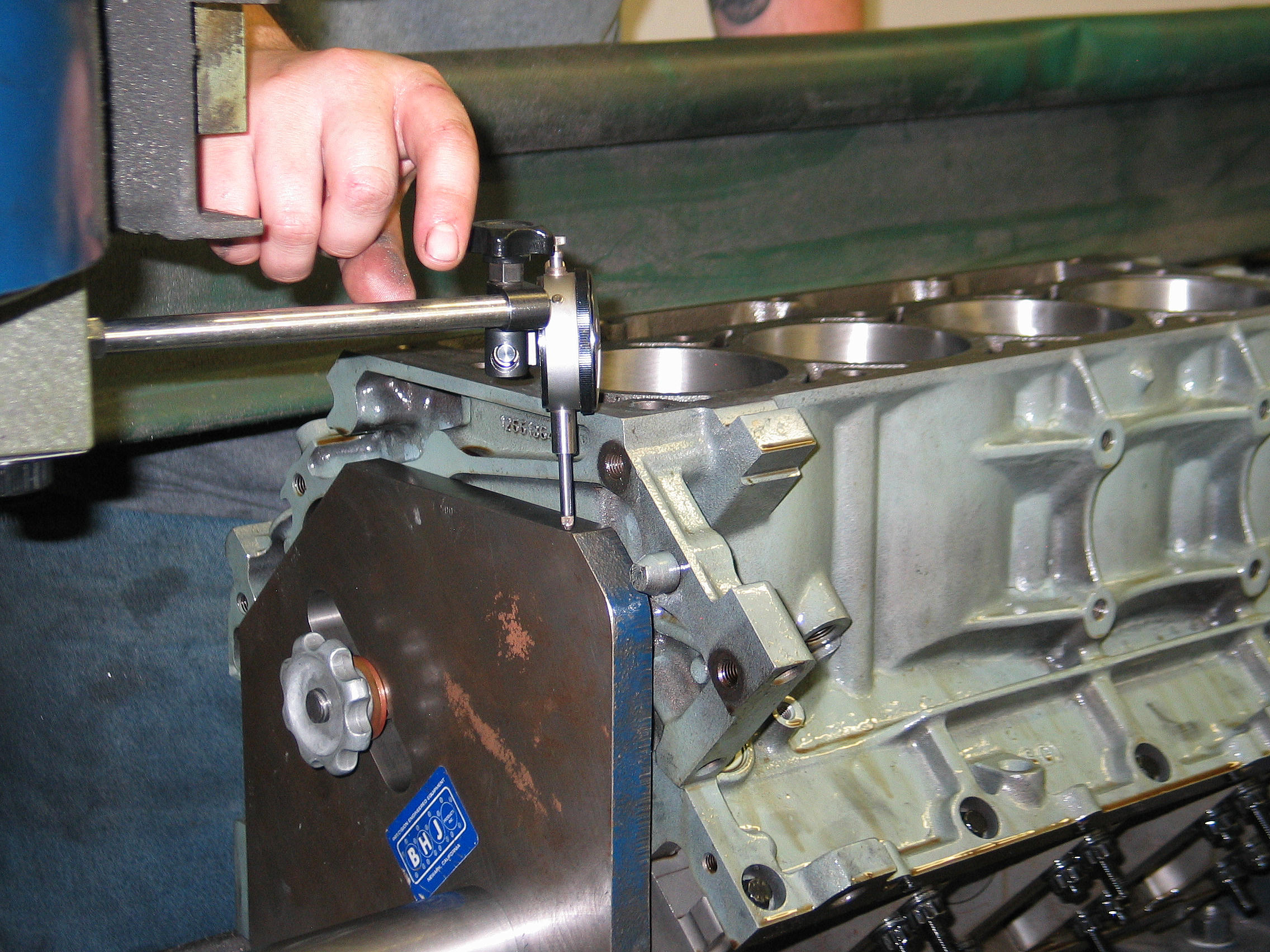
While the OEM block deck height is specified at 9.240 inch, our block’s left hand deck was on the tall side at 9.242 inches. Both decks were a bit off-camber — the left deck, for example, was low on the outboard area and too tall on the inboard surface. Justin milled both decks to achieve a final deck height of 9.230 inch. This gave us identical deck height on each side, running parallel to the crank centerline. In theory, this would bring our pistons 0.010 inch above deck, but we’ll determine this during mock-up assembly.
Following decking, the top edges of the cylinder bores were lightly chamfered, and the block and caps were washed and oil-sprayed for rust protection
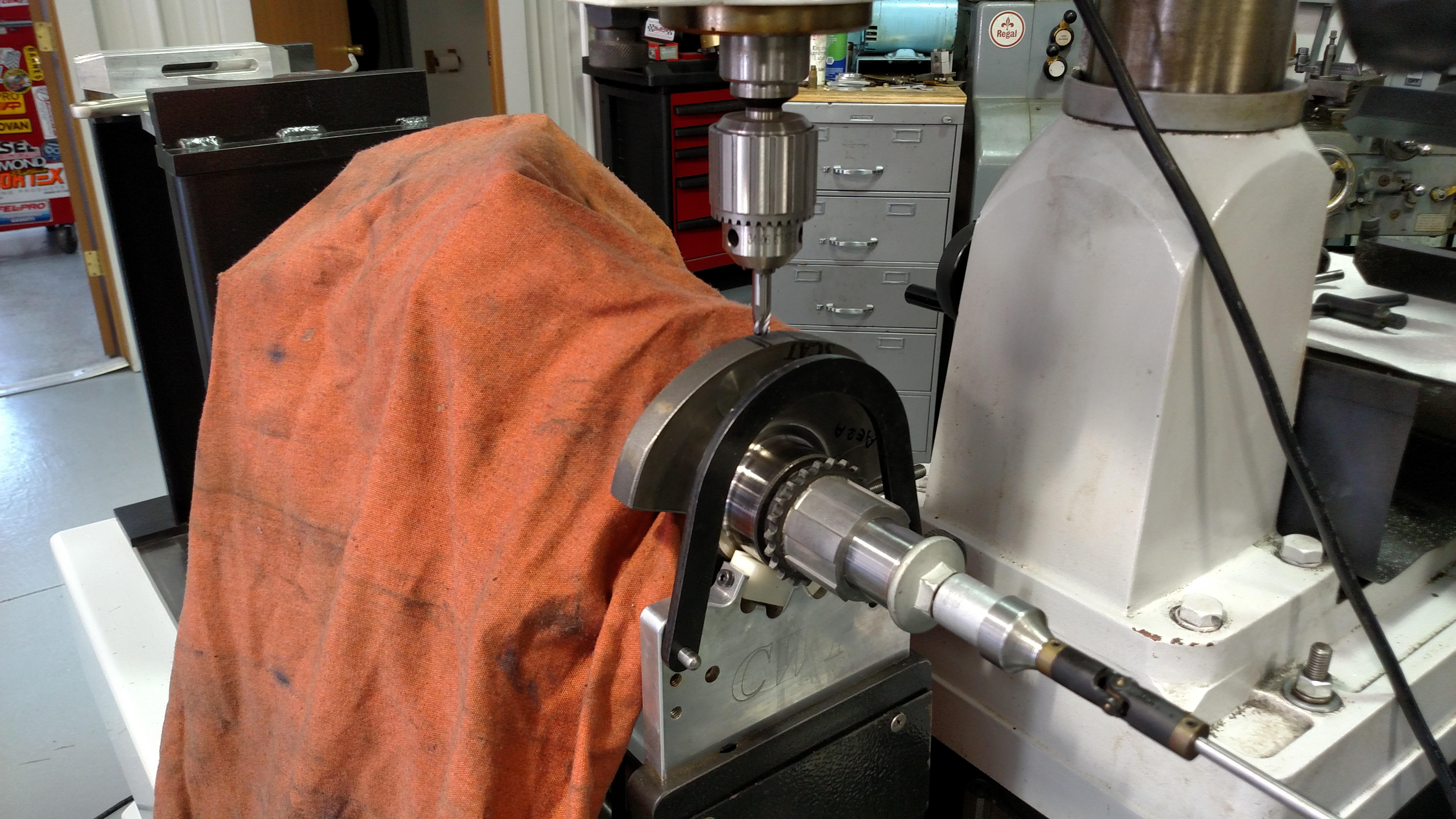
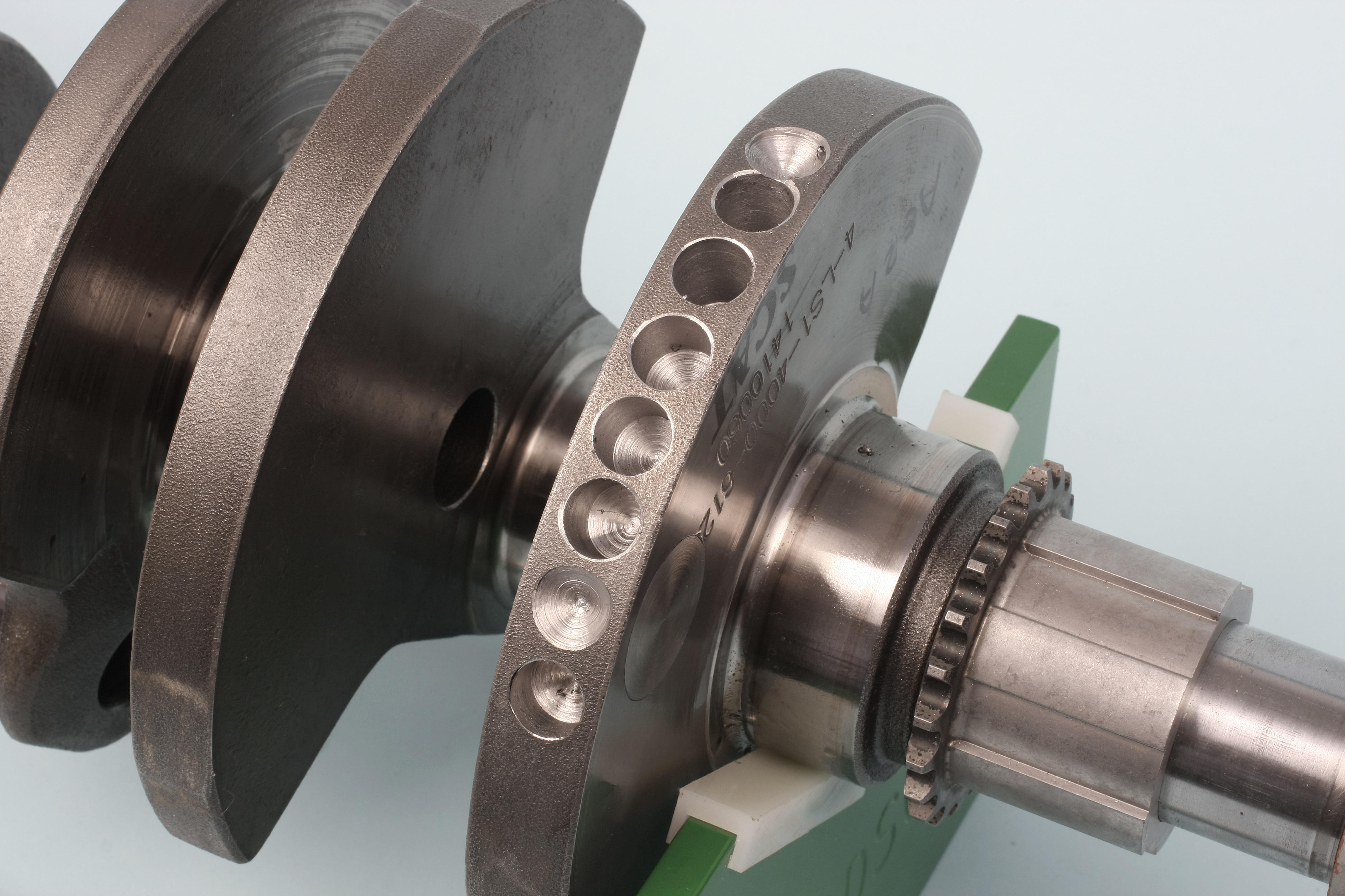
Rotating Assembly Balancing
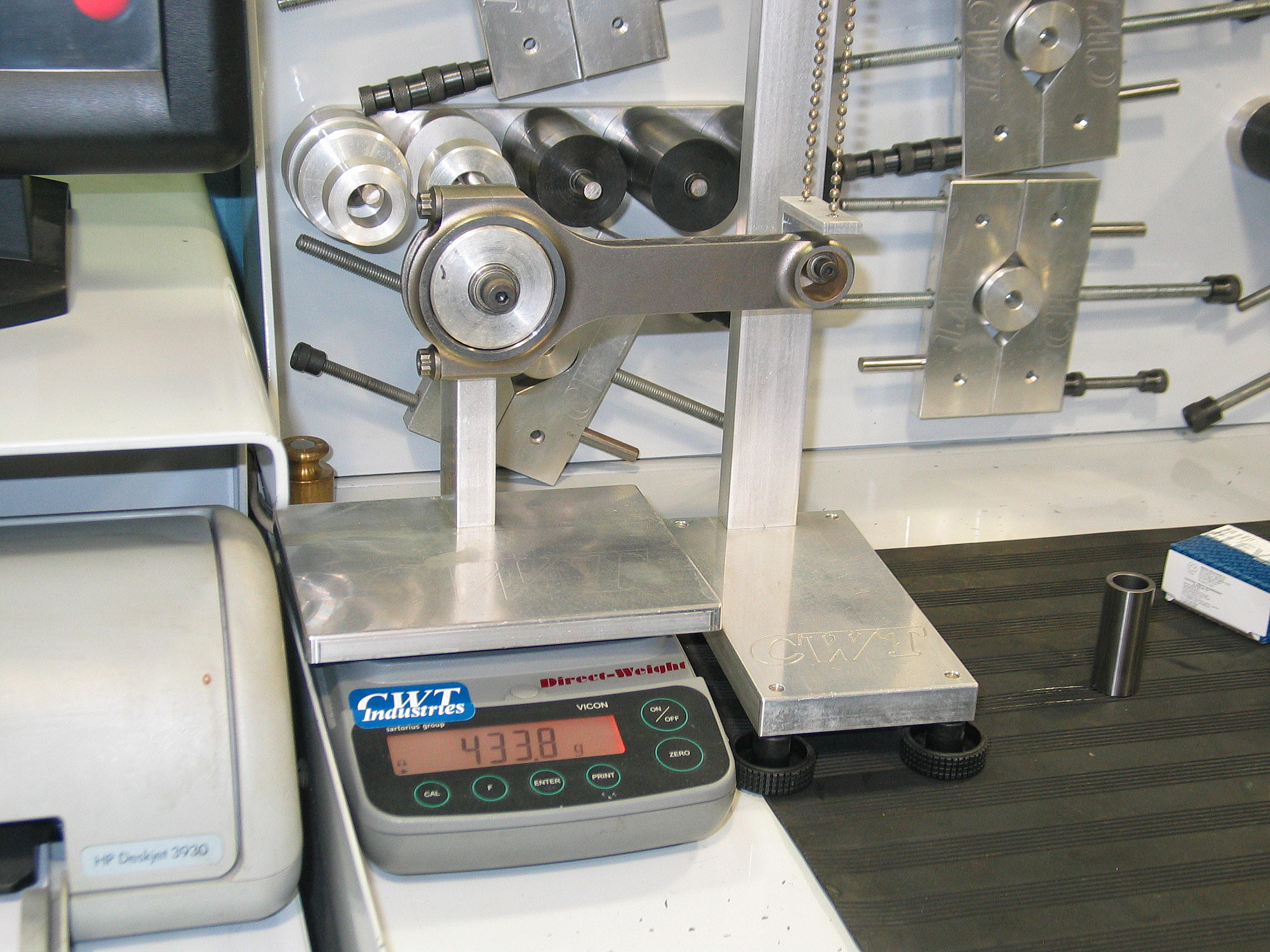
Balancing was performed at Fisher Racing Engines, Plain City, OH, on a CWT Multi-Bal 5000 balancing center. Owner and renowned sprint car race engine builder Charlie Fisher performed the balance work.
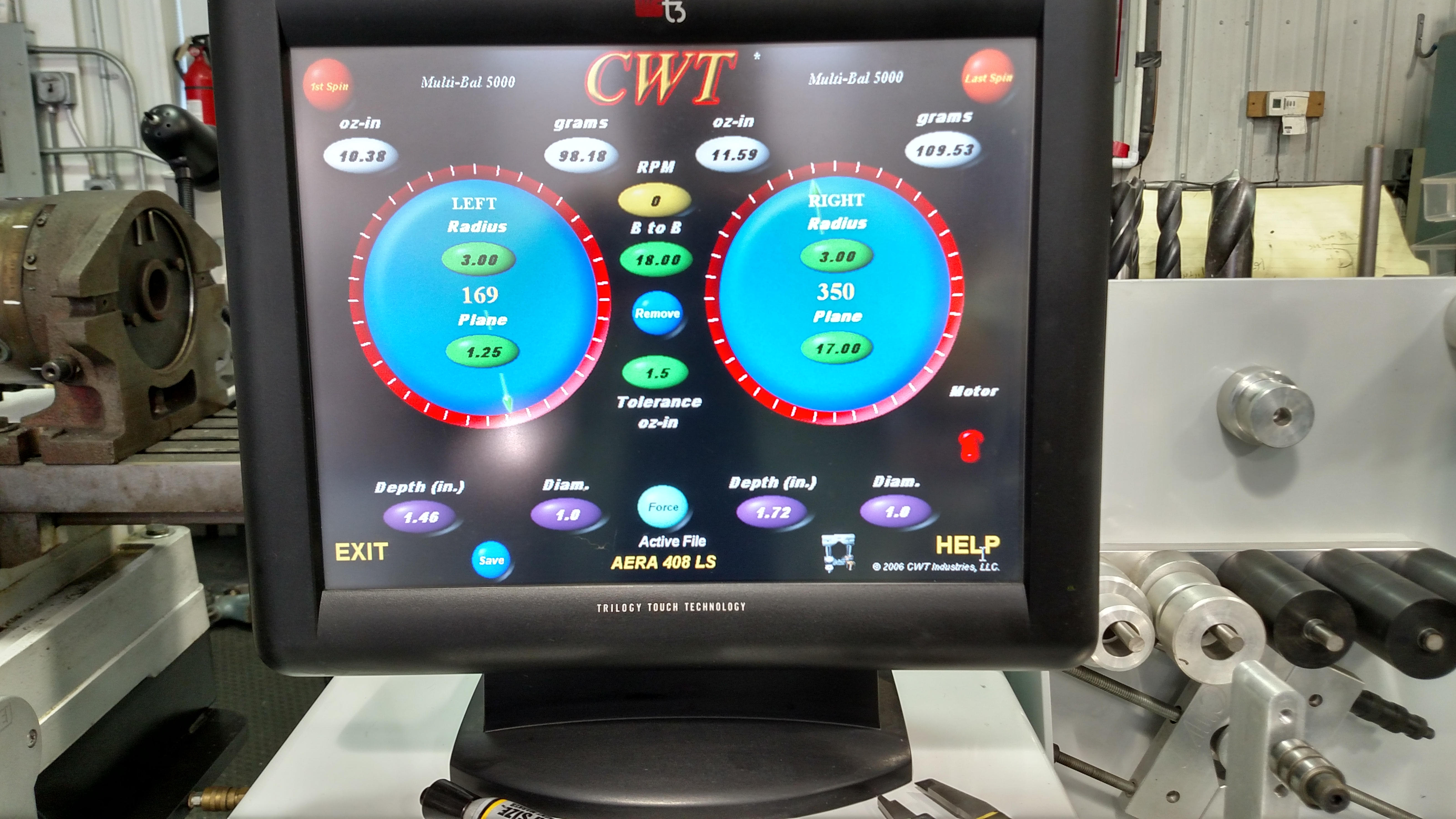
The CWT computer indicated we needed to remove 109.53 grams from the front and 98.18 grams from the rear of our Scat crankshaft. The weight reduction was due to the lightweight Icon pistons and wristpins. If we had chosen “run of the mill” pistons and rods, the crank may not have needed any balance correction at all.
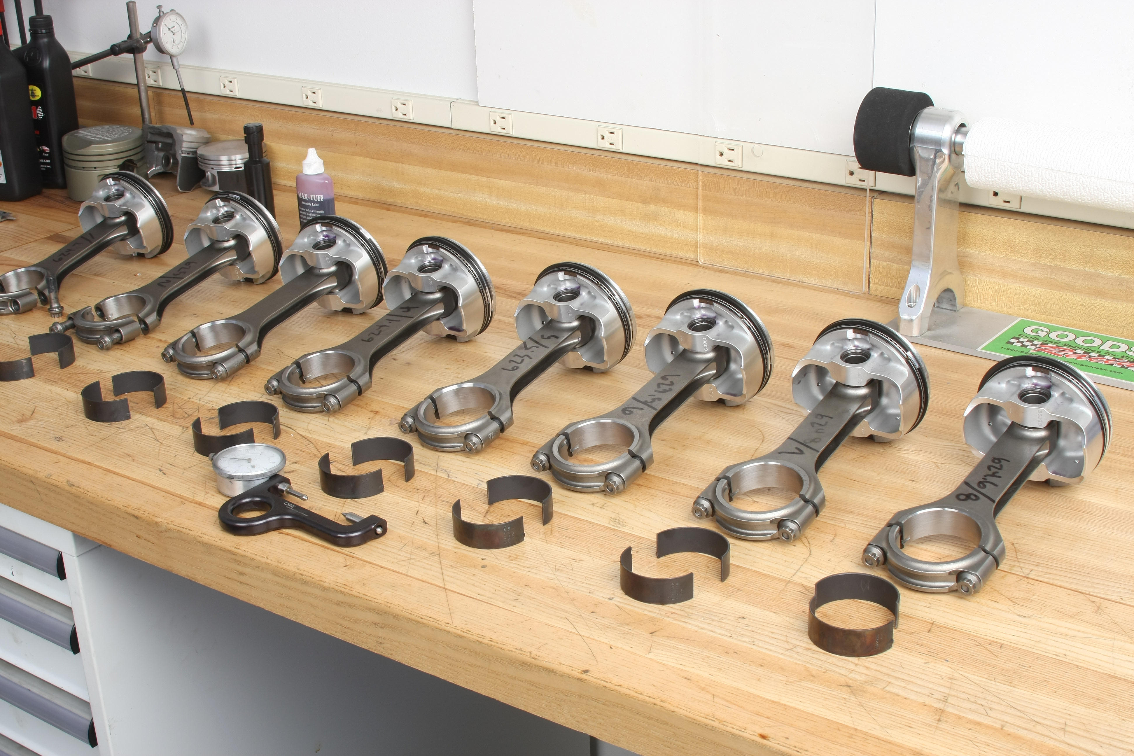
Our Scat rods ranged in weight from 432.40 to 433.60 grams at the big ends and 190.80 to 191.70 grams at the small ends. The Icon pistons ranged from 382.2 to 383.6 grams. While the weight differences were certainly acceptable, Charlie matched the heaviest pistons to the lightest rods and lightest pistons to the heaviest rods to optimize the assemblies.
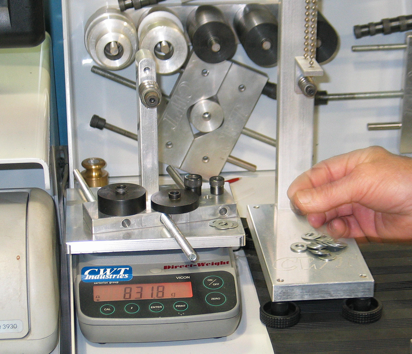
Since LS crank counterweights are relatively thin, we couldn’t drill one or two large diameter deep holes to balance the crank. Charlie drilled a series of holes on the front and rear counterweights, test spinning in stages until enough weight had been removed to hit the tolerance target. The imbalance was corrected to a final tolerance of 1.67 grams at the rear and 1.62 grams at the front. Considering that a single U.S. currency bill weighs one gram, bringing our crank down to these balance tolerances is pretty darned impressive.
Cam Bearings
With everything back in our shop, we began parts installation with the Clevite cam bearings. The cam was then test-fit to verify free rotation. The number 4 and 5 cam bearings required a bit of careful scraping for proper fit. The bore tightness was likely due to factory machining tolerances.
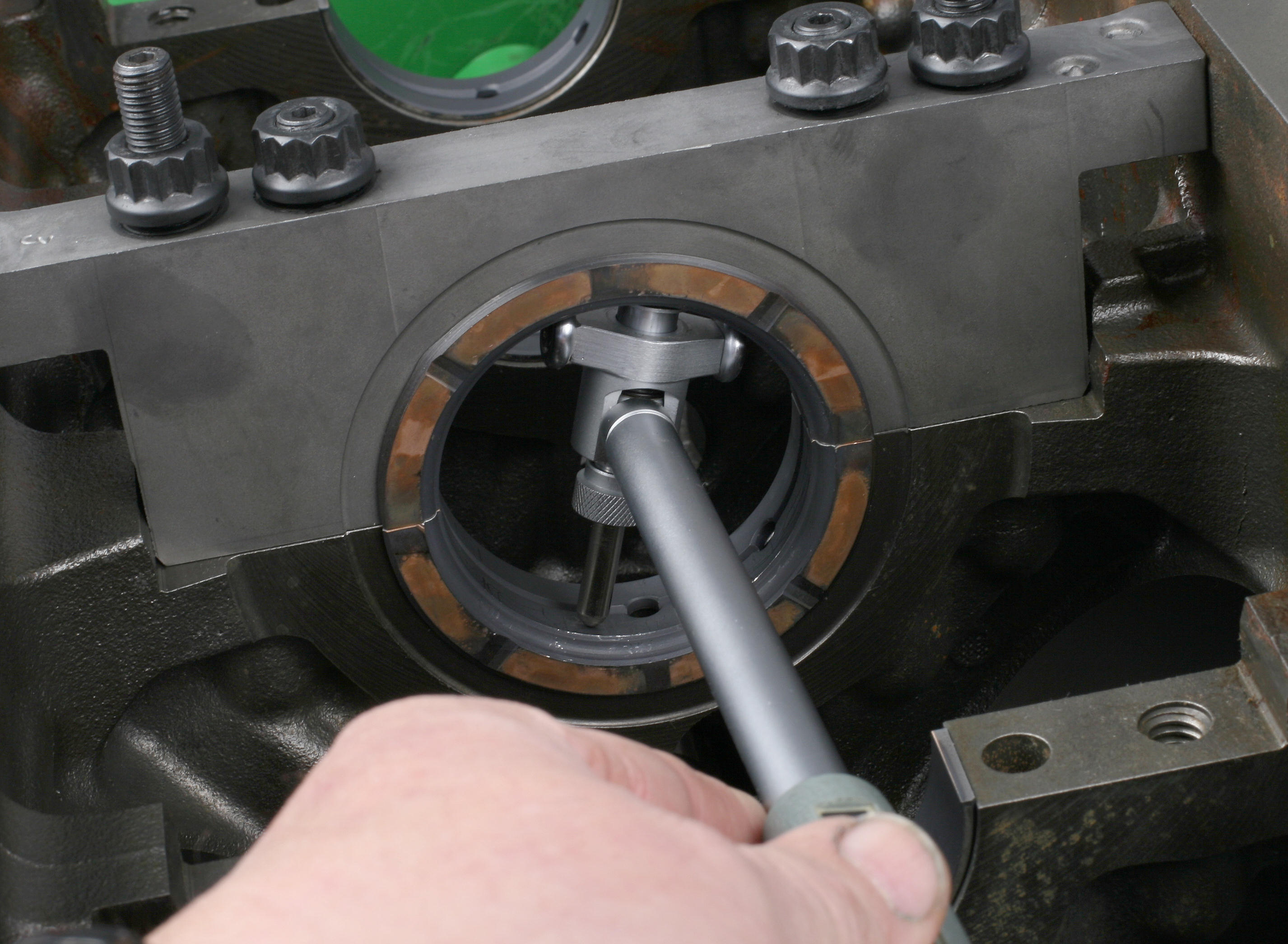
Crank Installation
We test-fit the crankshaft and checked oil clearance using standard size Clevite main bearings. Clearance was on the tight side at 0.0009 inch. We rechecked with Clevite MS-2199HX bearings, which provide an additional 0.001 inch of clearance. Oil clearance came up to 0.0017 inch. We gently sanded the bearing backsides and eliminated the minute raised areas caused by the identification stampings to get 0.00178 inch of clearance.
Once we were satisfied with crank fit, we installed the COMP Cams roller cam since access is easier with the crank out of the way. The cam journals and lobes were coated with Royal Purple Max Tuff assembly lube.
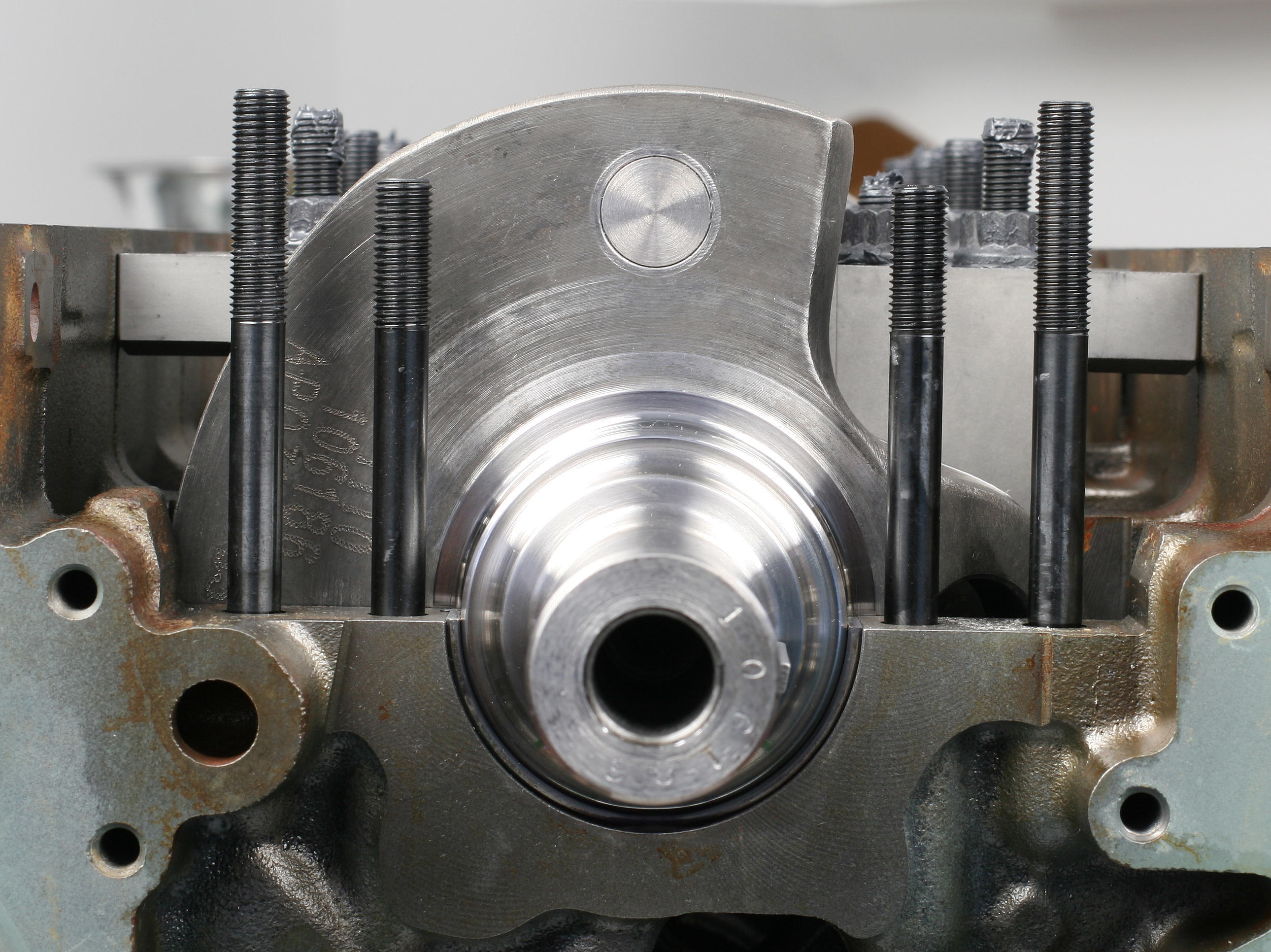
We reinstalled the main bearings and laid the crankshaft in place. The main studs were loosely installed; we chose to use ARP studs instead of OEM torque-to-yield (TTY) bolts. TTY bolts are tightened based on a torque-plus-angle tightening procedure that is time-consuming and requires the use of a special (and expensive) torque-angle wrench to do properly.
Each OEM cap is numbered for location (1-5), but pay particular attention to cap orientation. The “wings” at the outer edges of the caps must face towards the rear of the block with the exception of cap 5, where the wings must face forward. This will place the number stamps on caps 1, 2, 3, and 4 on the left (driver) side of the block, while cap 5’s number stamp is on the right side. I’ve seen these main caps installed backwards, which totally screws up bore alignment.
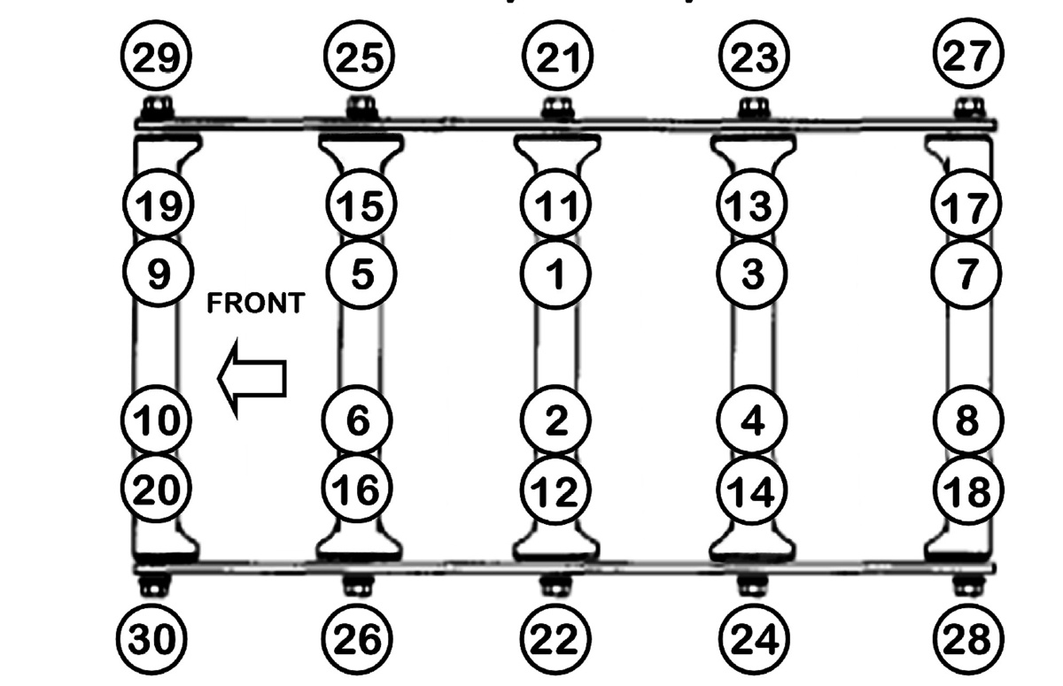
With the caps in place, the main studs were snugged finger-tight and each cap seated. We used a plastic hammer to tap the crank back and forth to help center and seat the #3 cap thrust bearings. The caps were tightened in progressive steps to 60 ft.-lbs. (inboard studs) and 50 ft.-lbs. (outboard studs). The 8mm side bolts were torqued to 20 ft.-lbs. Crank rotation was checked between all torquing steps. With everything in place, the crank rotated with little hand effort. It’s the happy feeling you always get when a crank “rolls like warm butter.”
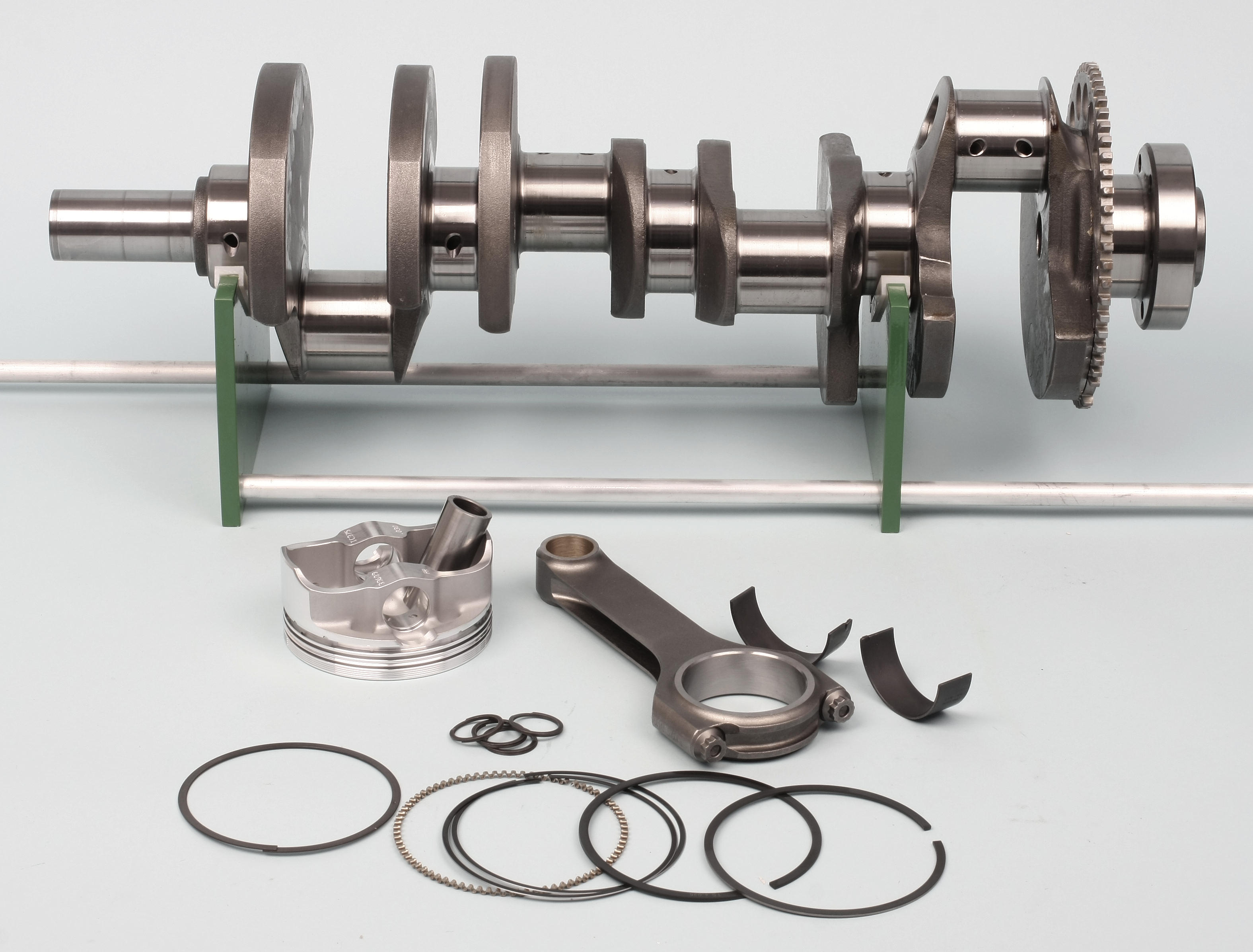
Pistons and Rings
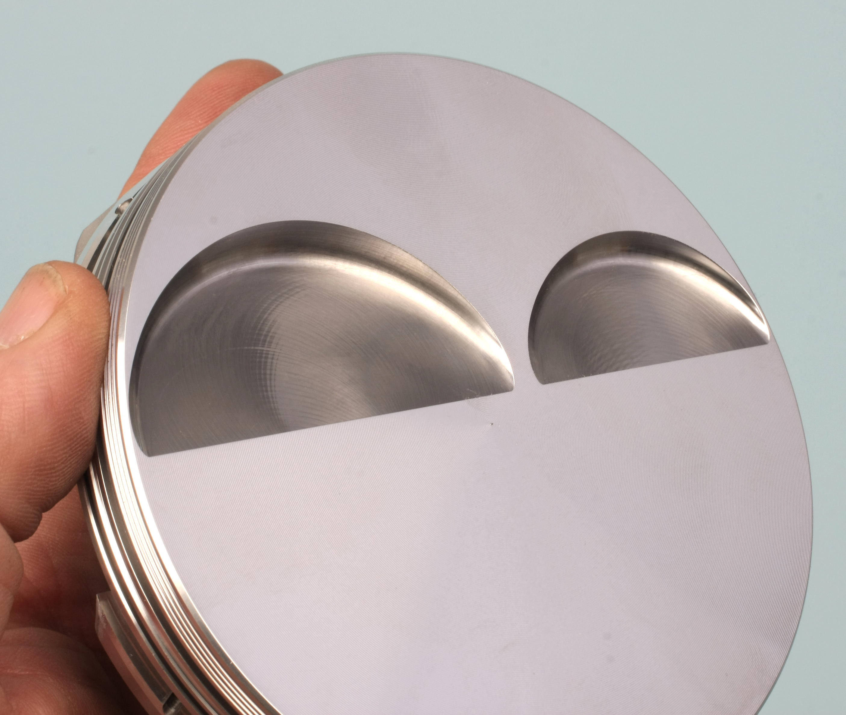
Our Icon forged pistons feature a flat-top design with 4.1cc valve reliefs. Compression distance (center of pin bore to dome) is 1.115 inch. Per Icon’s recommendation for a naturally aspirated street engine, the ring end gap factor is 0.004 inch per inch of bore diameter. We file-fitted the Total Seal top rings to a 0.016 inch gap and the secondary rings to 0.017 inch.
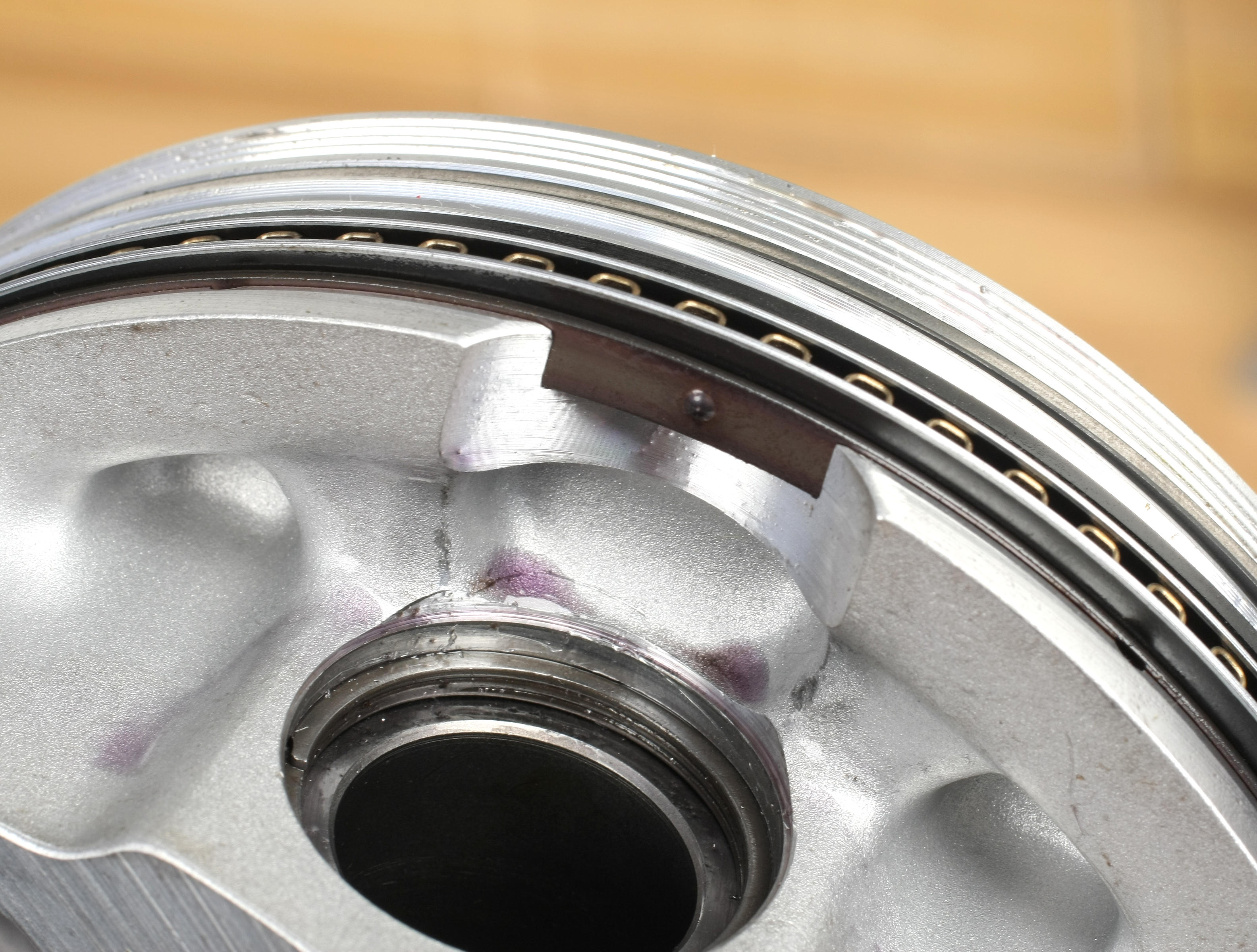
Due to the relatively short piston compression distance, the top of the pin bore intersects the oil ring groove, requiring the use of the provided spacer rails. When installing the support rails, note that each rail features a small male “dimple” protrusion. The rail must be installed with the protrusion facing down, centered at one of the pin bores. This prevents the rail from rotating out of place during engine operation, maintaining full support for the oil ring package.
Connecting rod and piston pairs were assembled according to our balancing results and the wristpins installed full-float style with spiral clips. We tested two rod bearing setups:
- Clevite CB-663-HNK standard upper and lower bearings
- Clevite CB-663-HNK standard upper and CB-663-HXNK lower bearings
With upper and lower standard bearings, oil clearance measured 0.0016 inch, which is within OE spec. With a standard upper and X-series lower bearing, we picked up 0.0006 inch of clearance (0.0022 inch). Based on that test fit, we opted for the standard uppers/X lower combination. This will work with 10W-40 weight oil and high revs. If we were to use a thinner oil, we would have gone with the tighter clearance provided by standard upper and lower bearings.
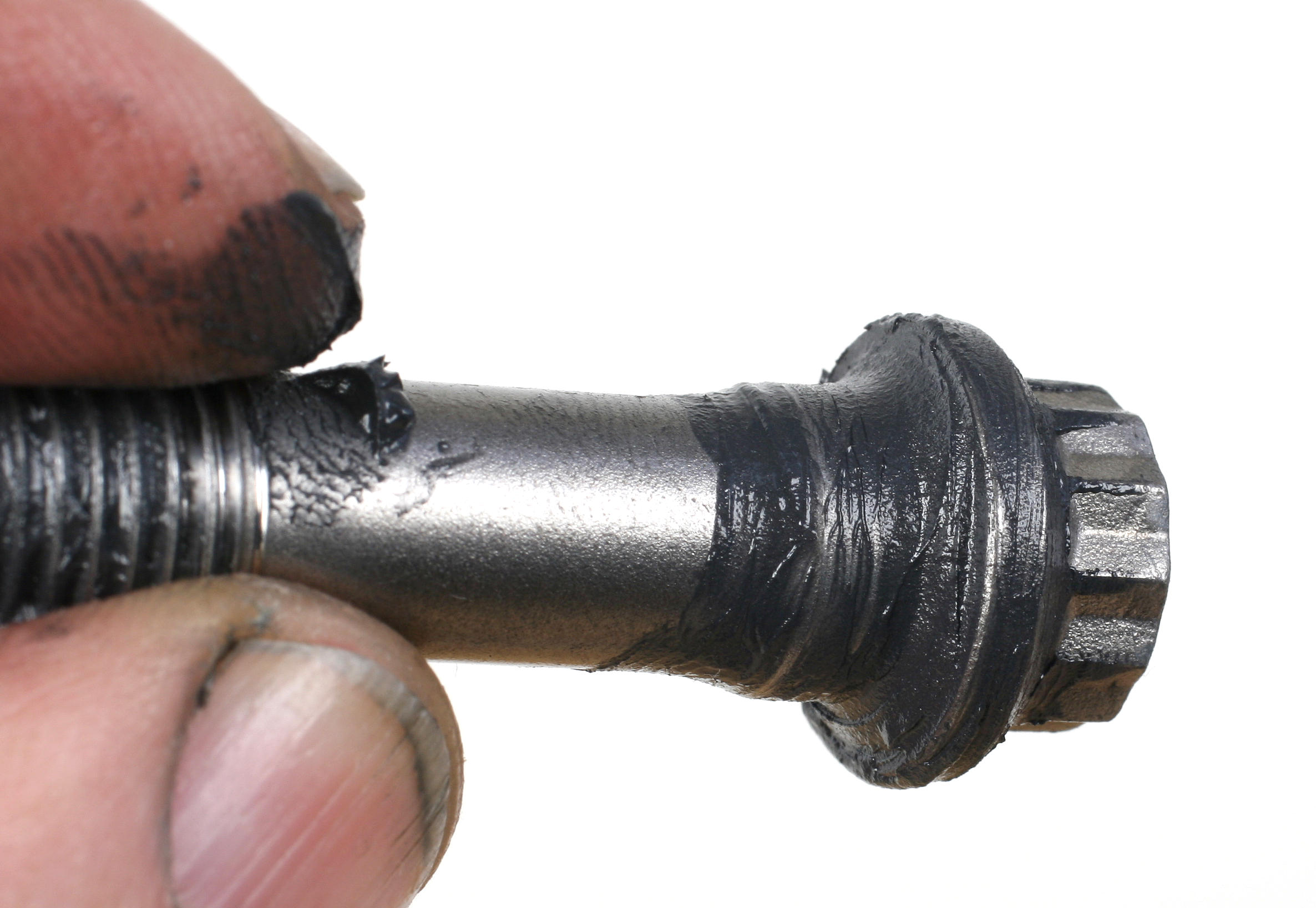
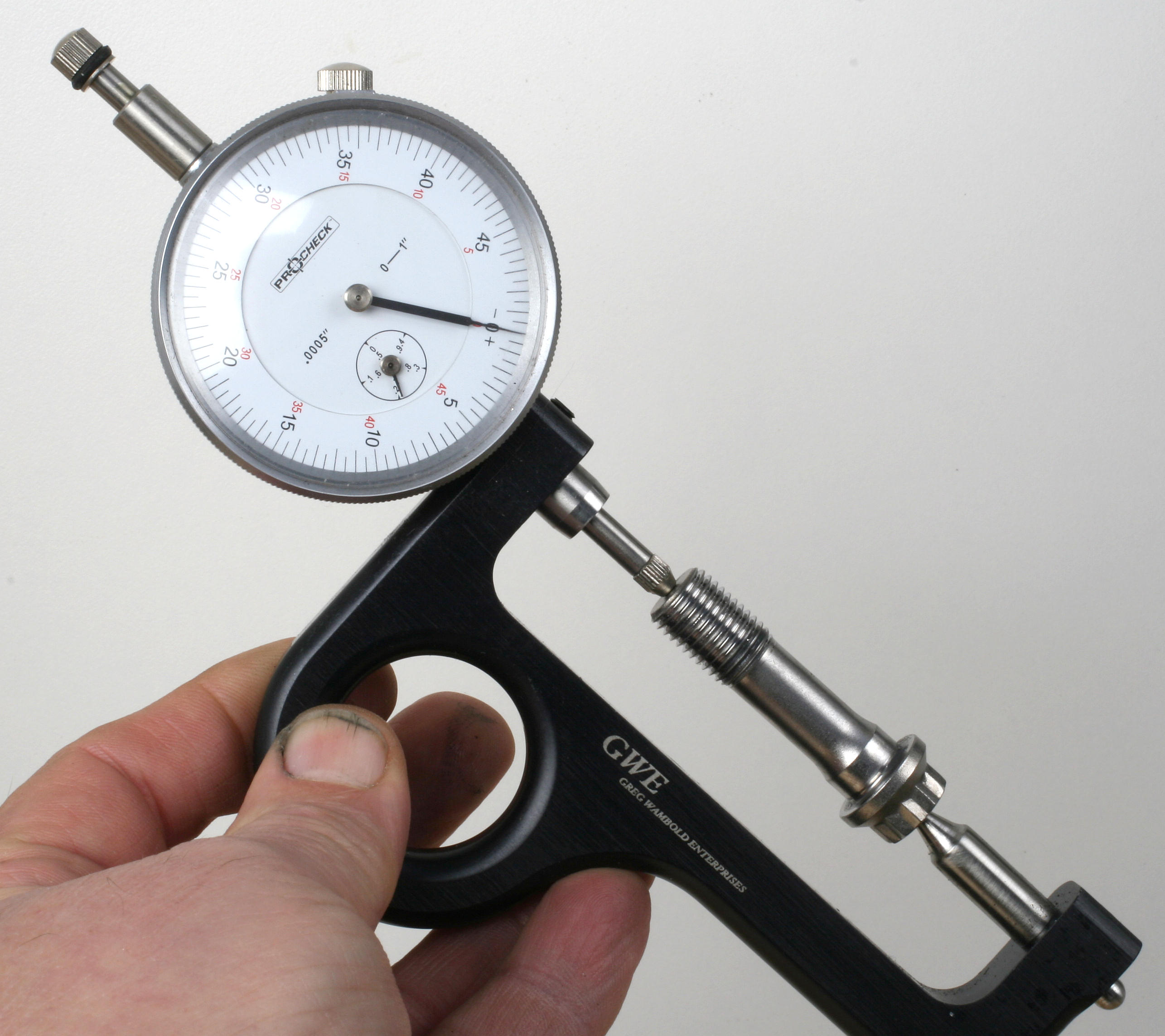
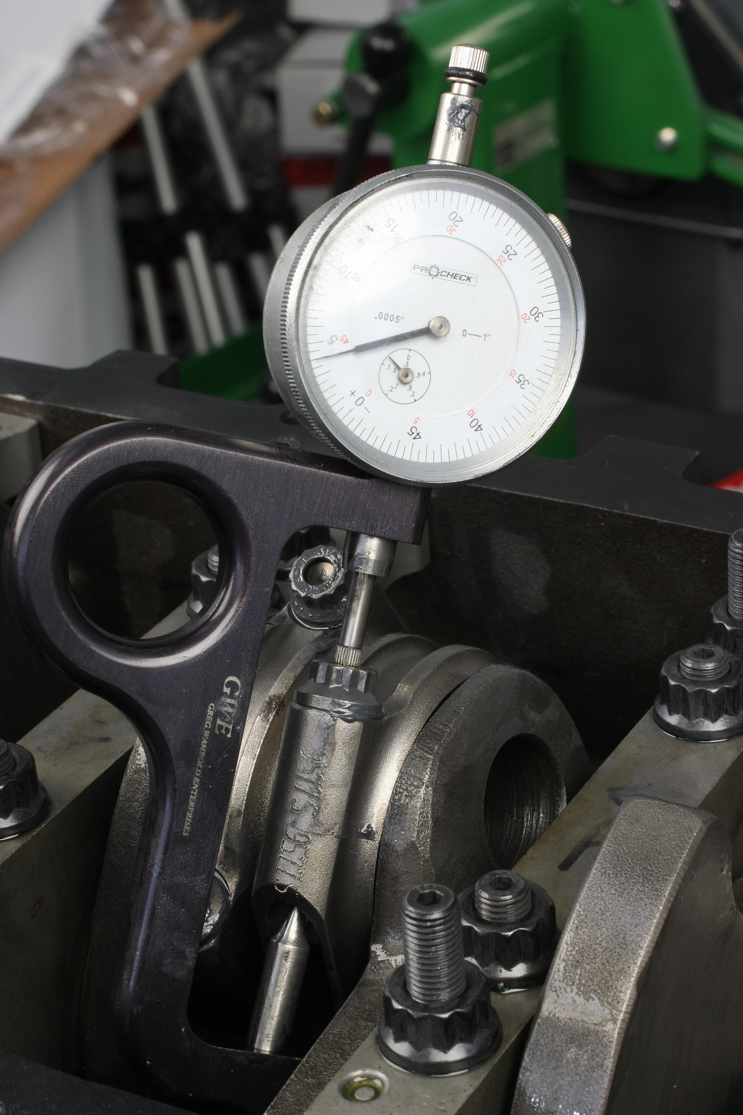
The rod bolts are 7/16 inch x 1.400 ARPs. For that specific bolt, Scat specs a torque value of 64 ft.-lbs. without exceeding 0.0045 inch of bolt stretch. After applying ARP moly to all threads and bolt underheads, the bolts were tightened to spec and checked for bolt stretch. Stretch spec’d out at an acceptable 0.004 inch.
Rod side clearance came out at 0.019 to 0.020 inch at all locations.
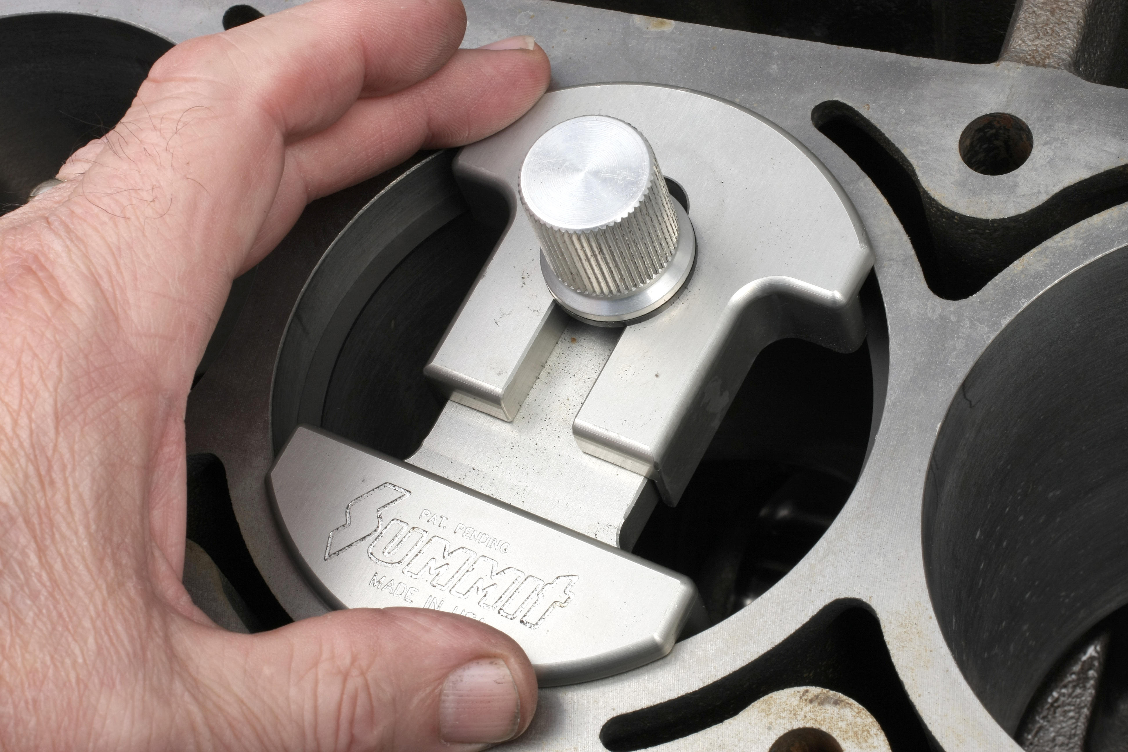
We installed the rod and piston assemblies with an adjustable ring compressor set at 4.0305 inch and an extended-nose piston hammer. The extra reach the hammer provided made it easier to work the piston/rod down with one hand while guiding the rod big end onto its journal on the crank.
What’s Next
In Part Two of Nighthawk LS, we’ll be covering the oiling system, heads, and valvetrain. We also cover sensor and cover installation, both of which can bite if you don’t know your way around an LS engine.
by Icon Pistons. (Image/Mike Mavrigian)
Comments