See all the articles in this Back in Black Nighthawk LS series here:


Timing System
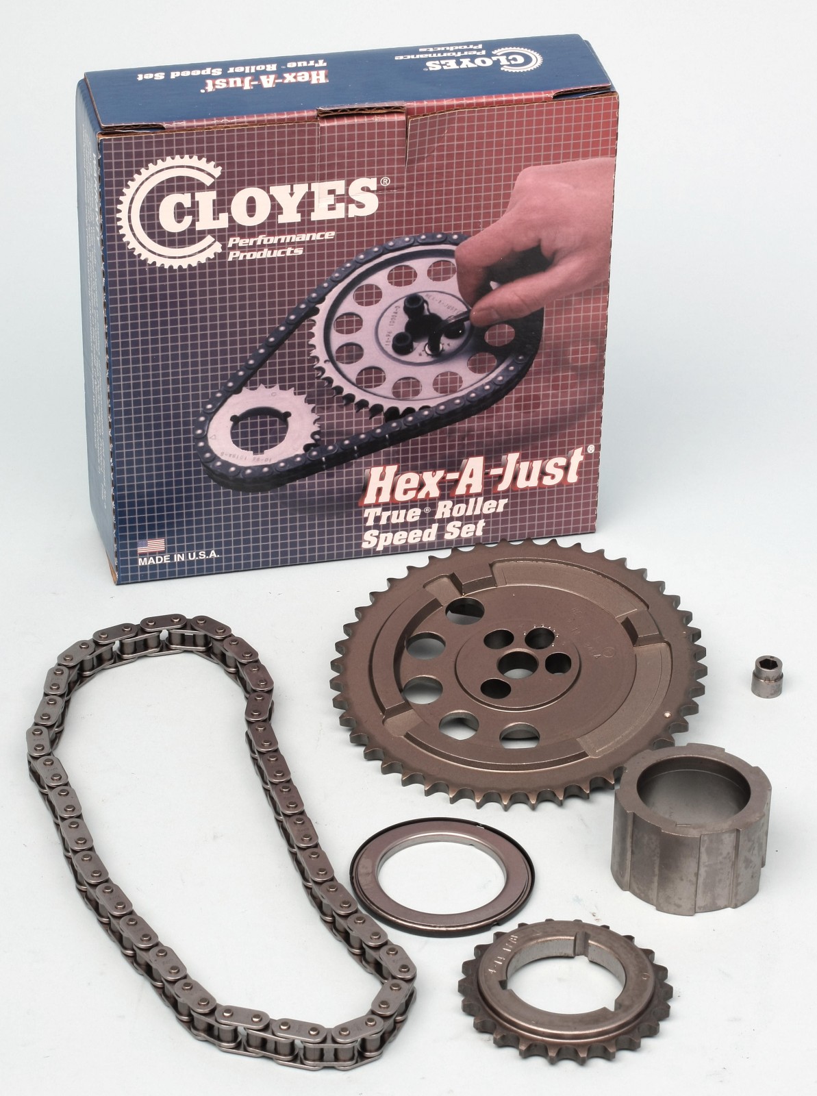
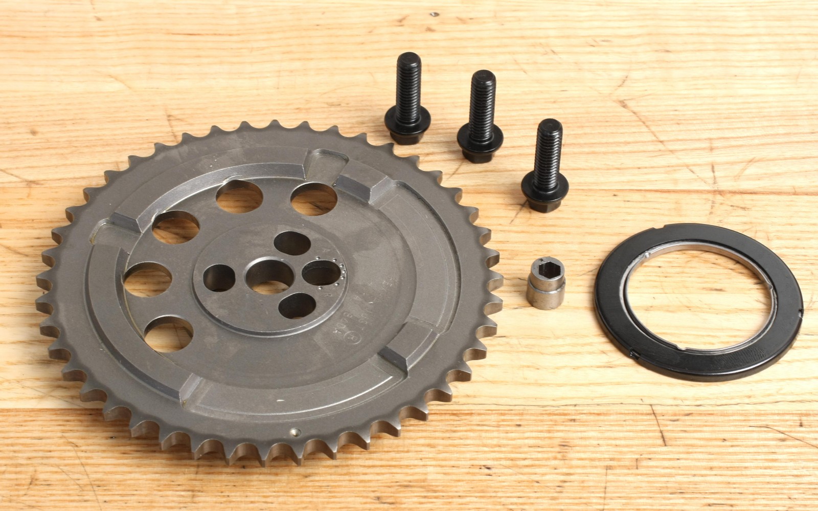
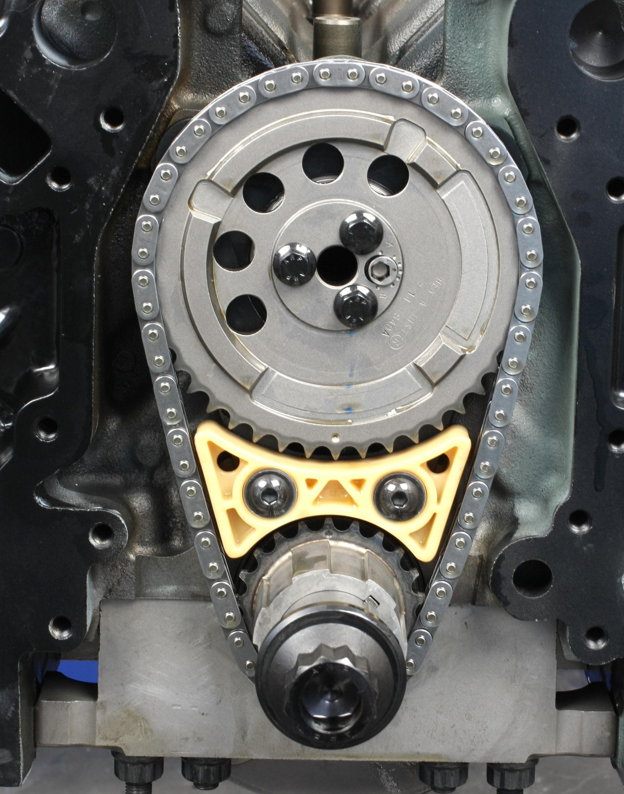
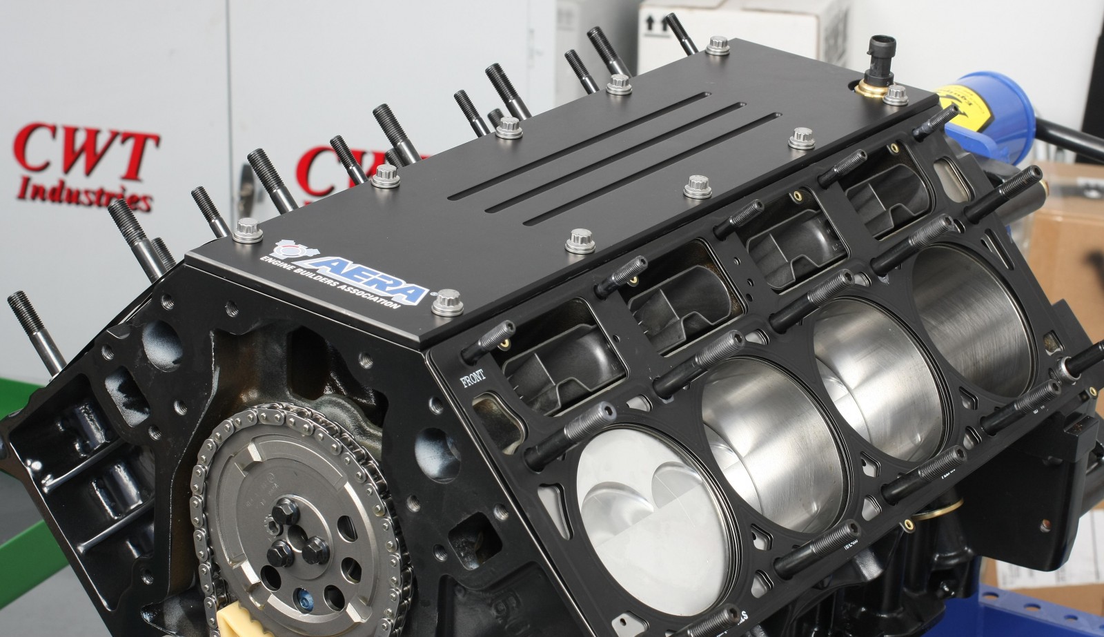
Our timing system is a Cloyes Hex-A-Just set. It includes the crank gear, chain, cam gear, oil pump drive gear, needle bearing unit and a cam timing adjuster bushing. The cam gear is compatible with a front-mounted (LS2 style) camshaft position sensor.
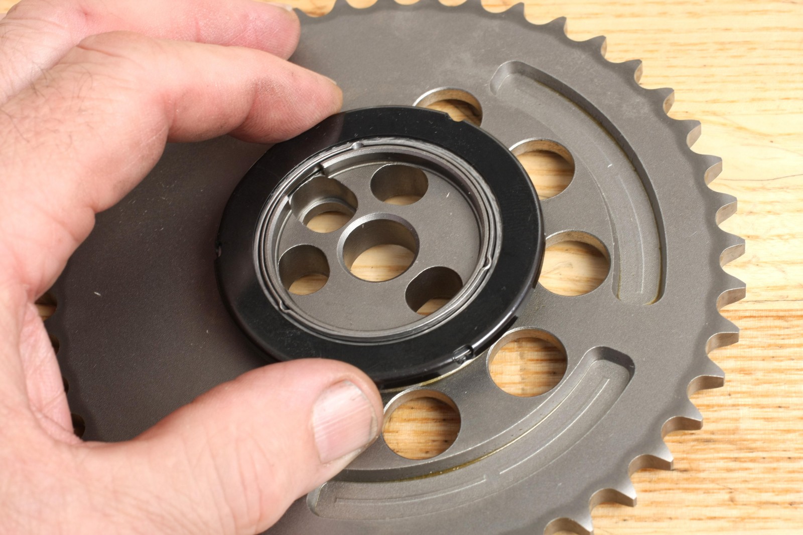
To install, position Number One piston at TDC, with the timing mark on the crank gear at 12 o’clock. Position the camshaft with its pin at approximately 3 o’clock. The roller bearing supplied with the set is installed between the cam nose and rear of the cam gear. The caged black side of the bearing must face the block so the bearing can rotate freely. The Hex-A-Just bushing is inserted into the cam gear from the rear of the gear. Install the cam gear and chain and verify that the timing dot on the cam gear is at 6 o’clock, facing the mark on the crank gear.
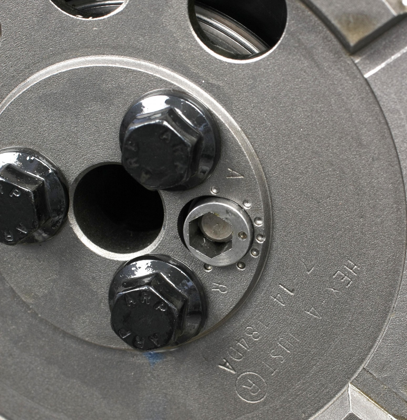
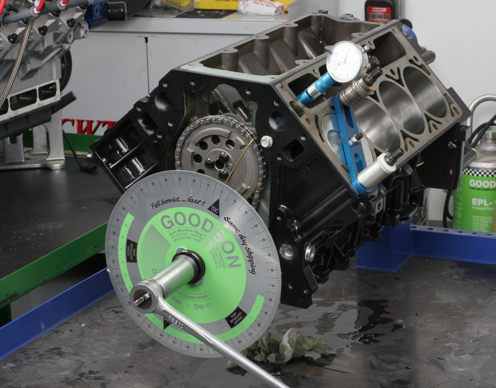
Hold the cam gear flush against the bearing and cam and finger-install all three cam gear bolts. Snug the bolts to eliminate any slop in the cam gear. Roll the crank back and forth, bringing it back to the gear alignment marks. Crack the three bolts loose just enough to allow gear adjustment. Use a 1/4-inch hex wrench to rotate the Hex-A-Just bushing to your desired cam timing. For now, we set this at zero. The cam timing was then checked using a degree wheel.
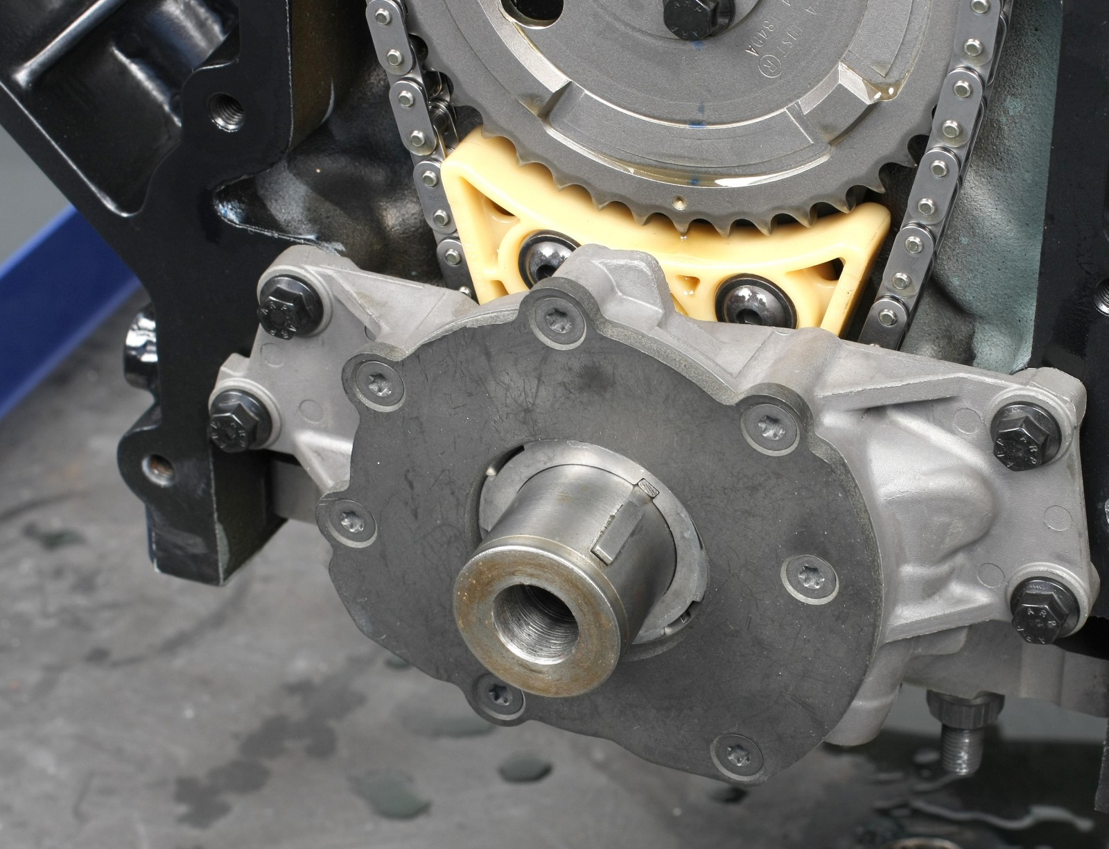
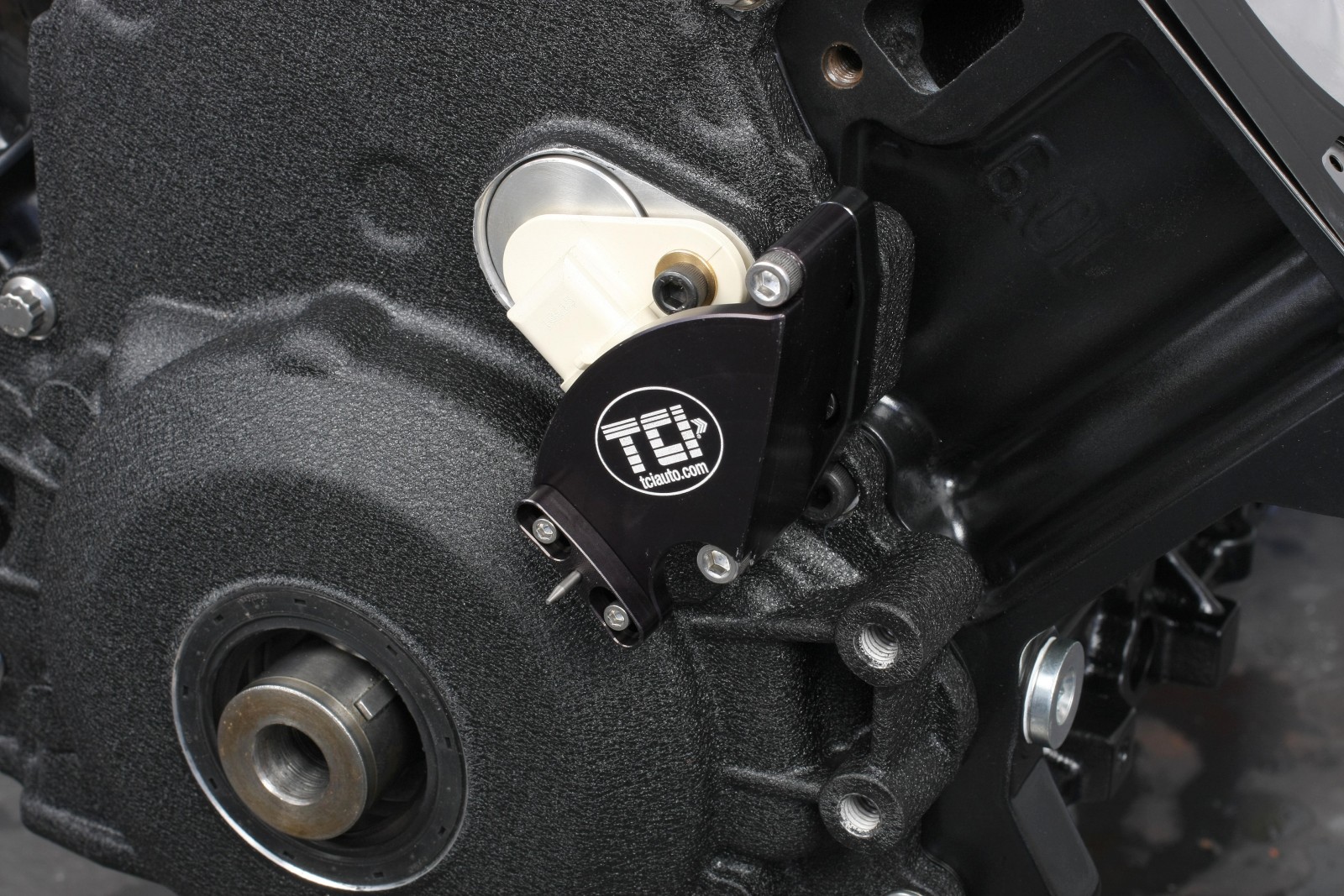
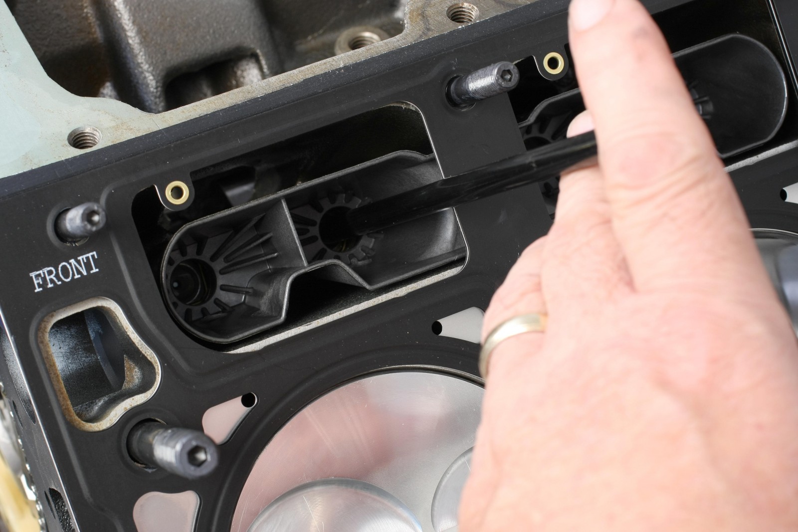
A chain damper helps control timing chain harmonics. Some LS blocks come with this damper, but our iron LQ9 block does not have bolt holes to install one. The damper adapter from Trick Flow features a bracket that shares the bottom three bolts for the camshaft retainer plate; the plastic damper bolts to the bottom of the bracket.
Cover Plates
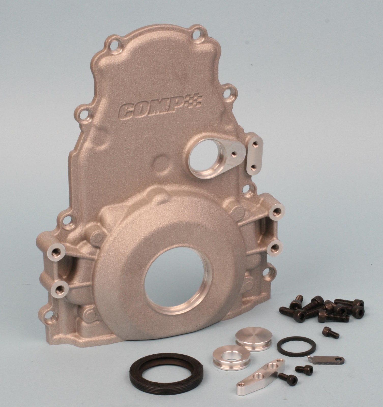
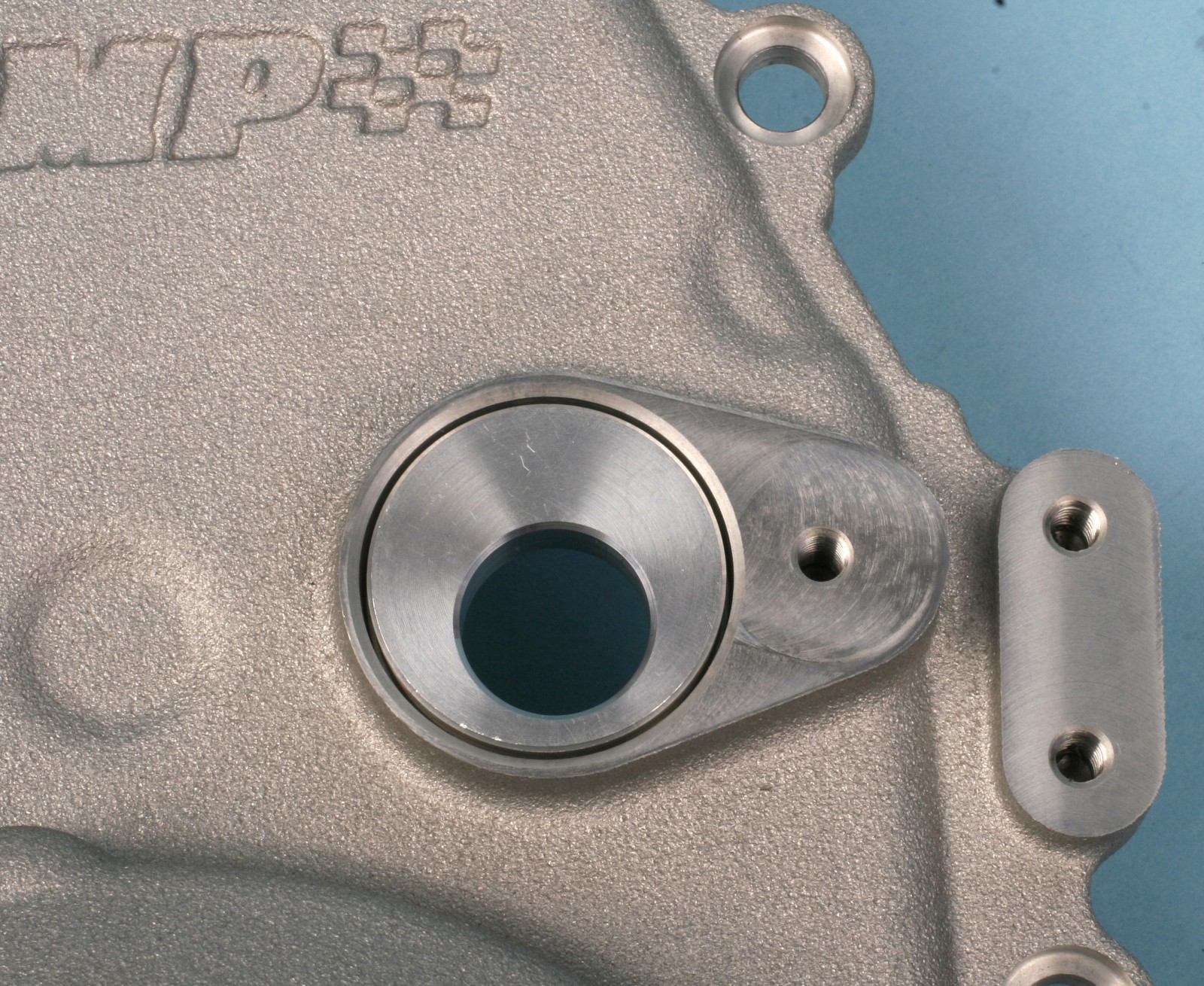
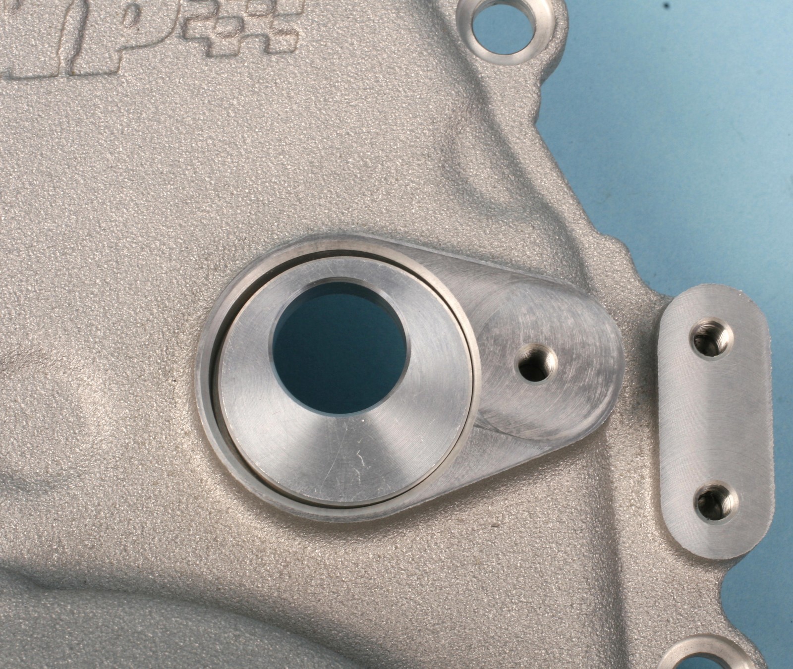
The front timing cover is from COMP Cams. It can accommodate a front-mounted (LS2 type) cam position sensor and allows you to use a big block Chevy timing pointer. The hole for the cam sensor has an adapter plug with an offset hole for the sensor. The supplied square-profile O-ring fits on the adapter for sealing. If the block is stock and features a standard cam bore location, the adapter plug is installed with the sensor hole at 6 o’clock. If you’re dealing with a raised-cam block, the sensor hole should be positioned at 12 o’clock.
The front cover is supplied with black oxide socket head cap screws that nestle into the mounting holes’ counterbores. We decided to use 8mm ARP 12-point bolts. Since bolt head flanges were a bit too large to seat in the counterbores, we filled the counterbores with two small washers behind each bolt head. The bolt location behind the timing pointer adapter is too shallow for an ARP bolt head, preventing the timing pointer adapter from seating flush. You can grind a notch on the backside of the lower area of the adapter to fit the ARP bolt, or use a socket head cap screw. Since the adapter hides this fastener, we used the screw.
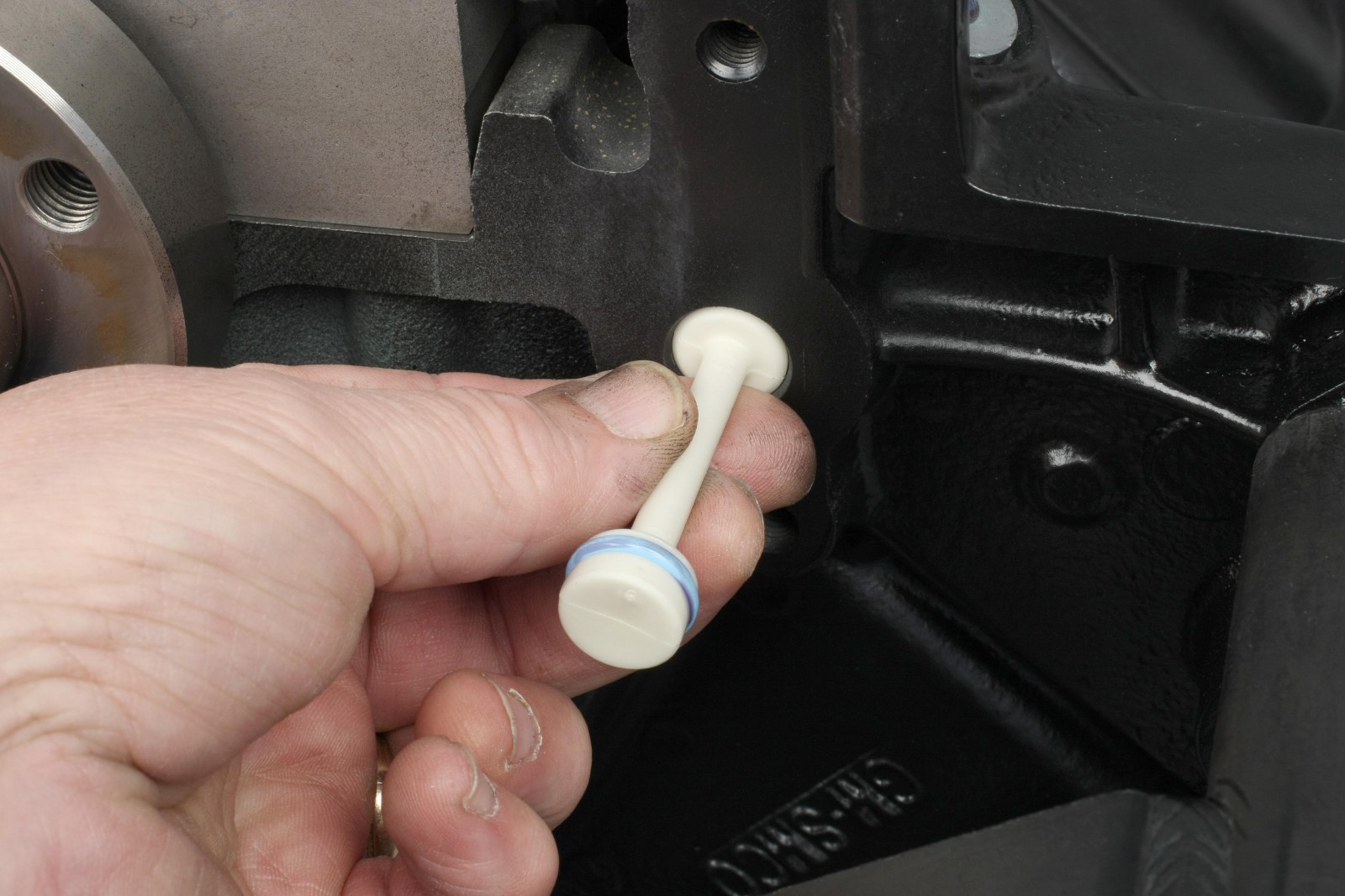
The rear engine cover (which houses the rear main seal) is a new OEM unit. Prior to installing the cover, we fit a new OEM plastic oil galley plug into the rear oil galley hole. After installing the rear main seal and the white nylon seal guide, the rear cover is carefully and squarely pushed onto the block, centering the crank flange to the seal guide. The guide prevents the rear main seal lips from folding rearward. Once the cover is fully inserted, the guide pops off.
Instead of using an ugly OEM valley plate, we made one from .250-inch thick 6061 aluminum. The cover is six inches wide and 23 3/8 inches long and fits flush front-to-back on the block. We bored an access hole in the left rear to clear the oil pressure sensor, allowing enough clearance to fit a 15/16-inch thinwall socket. The underside of the plate was CNC groove-machined to mimic the OE gasket path. The groove accepts a 3/32-inch O-ring strip to provide sealing.
There are two recesses in the casting at the top front of the block. We filled these in with All-Metal body filler to create a flat surface for the front of the valley plate. All-Metal filler is a high-density, aluminim-impregnated filler that is very hard and withstands block operating heat. The plate was installed using ten 8mm ARP 12-point bolts.
Cam Sensor and Timing Pointer
The camshaft position sensor fits in the offset hole in the COMP cover’s sensor adapter. The sensor O-ring was lightly lubed and inserted; the sensor’s mounting tab was secured to the cover with a 1/4-20 socket head cap screw. The timing pointer adapter included with the COMP cover adapter is drilled and tapped to accept any big block Chevy adjustable timing pointer. We fit a TCI timing pointer to the adapter with the 1/4-20 socket head cap screws included with the pointer. They were a tad long, so we shortented them by 3/16 inch.
An OEM cam sensor harness is required, available at any GM dealer. We removed the ugly steel bracket from the harness and covered the wires with black braided loom sheathing. We fabricated a small aluminum mounting plate with an Adel clamp to secure the harness to the front cover. The cover was tapped for a 10-32 cap screw, which secured the clamp to the mounting plate. The cam sensor harness should be plugged into the sensor prior to mounting the timing pointer. The harness can be connected with the pointer installed, but access is tighter.
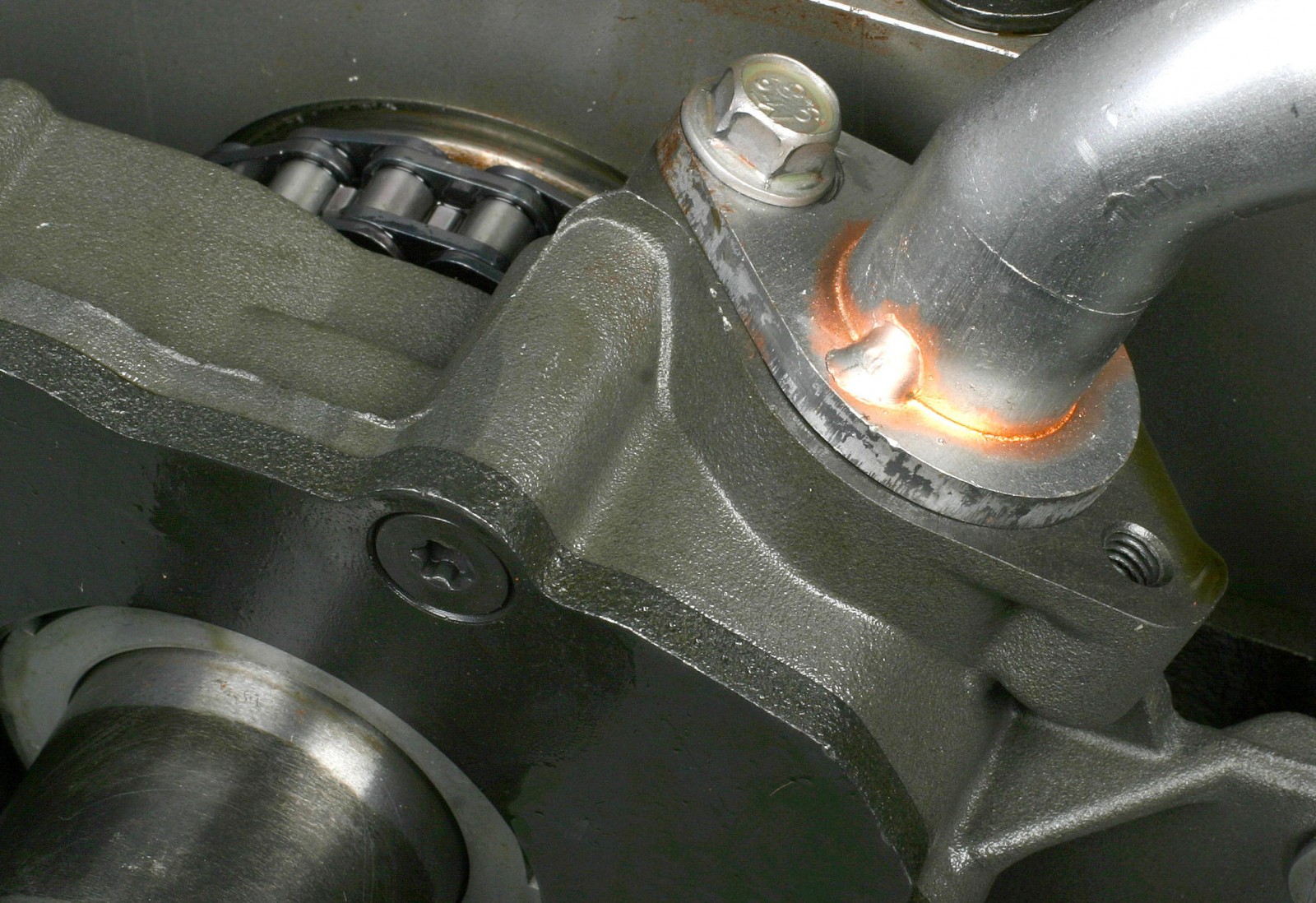
The front oil galley hole was plugged with a new OEM expansion plug lightly coated with RTV prior to installation. The plug was tapped flush with the block surface.
Lifters
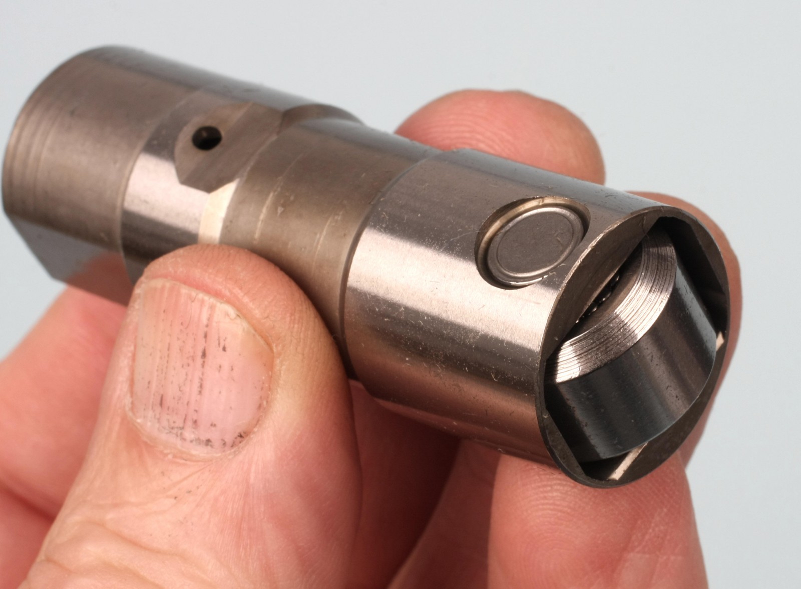
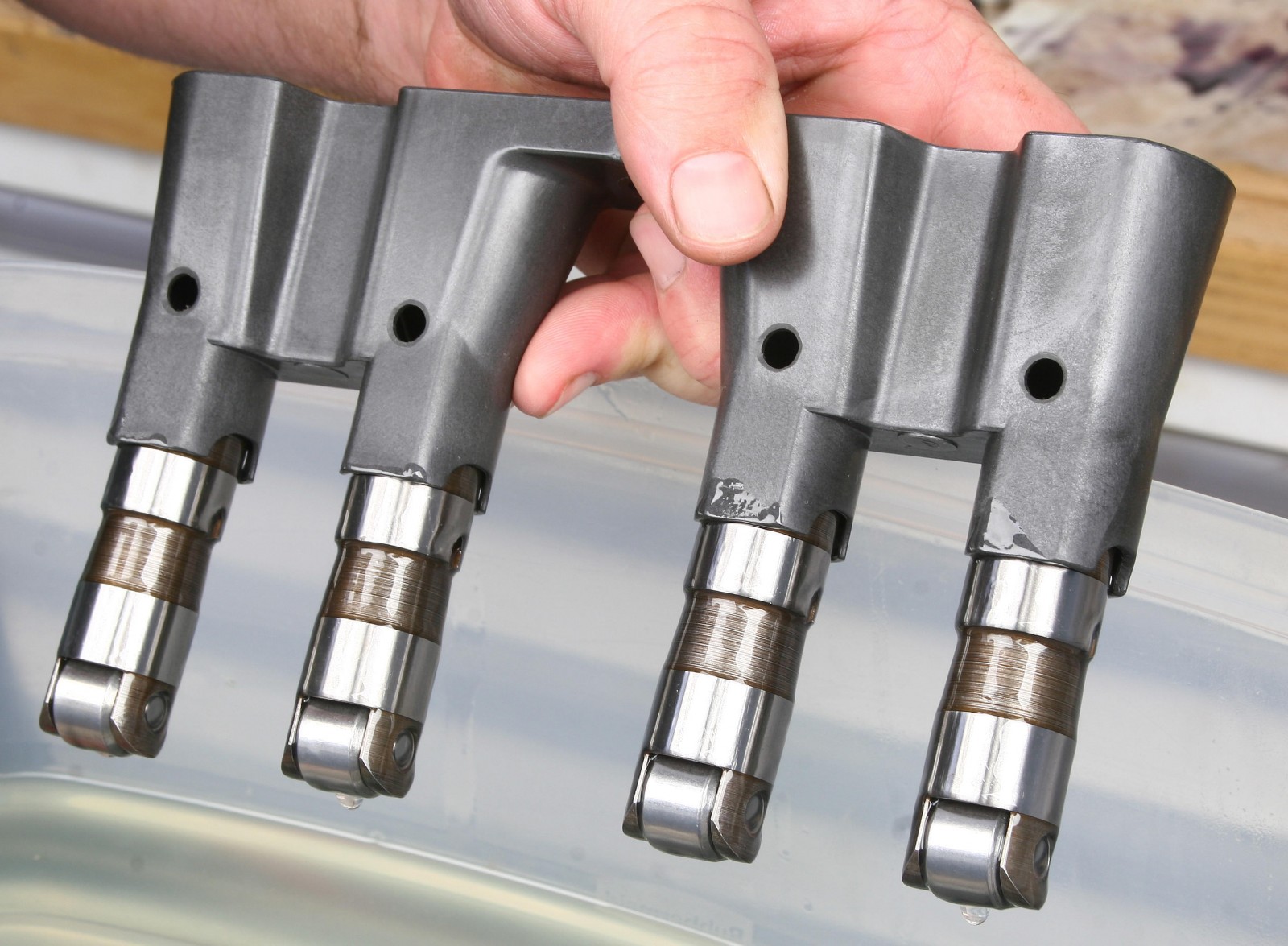
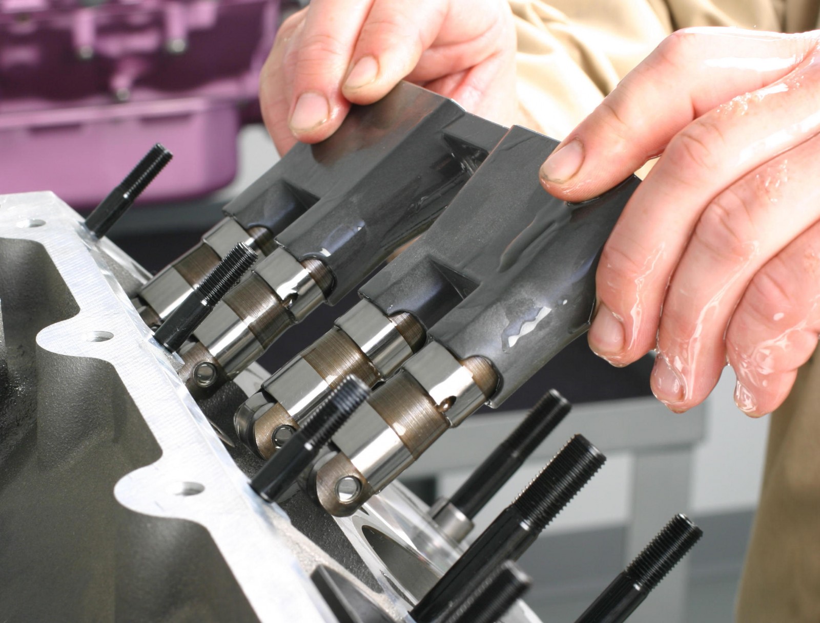
We used OE-style lifter guides for this build. The four plastic lifter guide trays have opposing flats to retain the roller lifters in plane with the cam lobes. Before installing the lifters to the trays, we drilled 5/16-inch oil drain holes on the outboard side of each guide tray. This prevents oil from puddling up inside the tray wells and flooding the lifters, The COMP Cams hydraulic roller lifters were coated with 30W oil and secured to the lifter trays. Each tray is mounted to the block with a single new 6mm shouldered bolt, torqued to 106 in.-lbs. (with medium threadlocker).
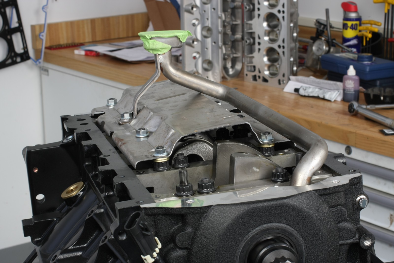
Oil Pump, Windage Tray, and Pickup
The Melling oil pump was secured to the block with four ARP bolts torqued to 18 ft.-lbs. Temporary 0.0005-inch shims were placed around the perimeter of the crank snout’s pump drive gear to carefully center the pump bore relative to the crank snout.
If you use a GM windage tray like we did, three of the eight bolt holes in the tray need to be enlarged to accommodate the ARP main studs, which measure 0.390 inch in diameter. Open up the three holes to 0.400 inch.
When using a stroker crank, install the tray and rotate the crank to check for interference with the connecting rod big ends. It’s common for the rod bolt heads to contact the tray. We fixed the problem by adding two 0.095-inch thick washers between the main cap nuts and tray at seven of the eight bolt hole locations. This provided us with about 0.100-inch clearance between the tray and rod bolts.
The left side area of the windage tray where the oil pickup tube bracket attaches to a main stud had to be clearanced to allow the pickup tube support bracket to align with the main stud and fully seat. This was done by hogging out the entire area where the tube bracket interferes, including the tray’s bolt hole. This allows you to mount the pickup tube bracket directly to the main stud with no spacers or tray material to alter the pickup screen height.
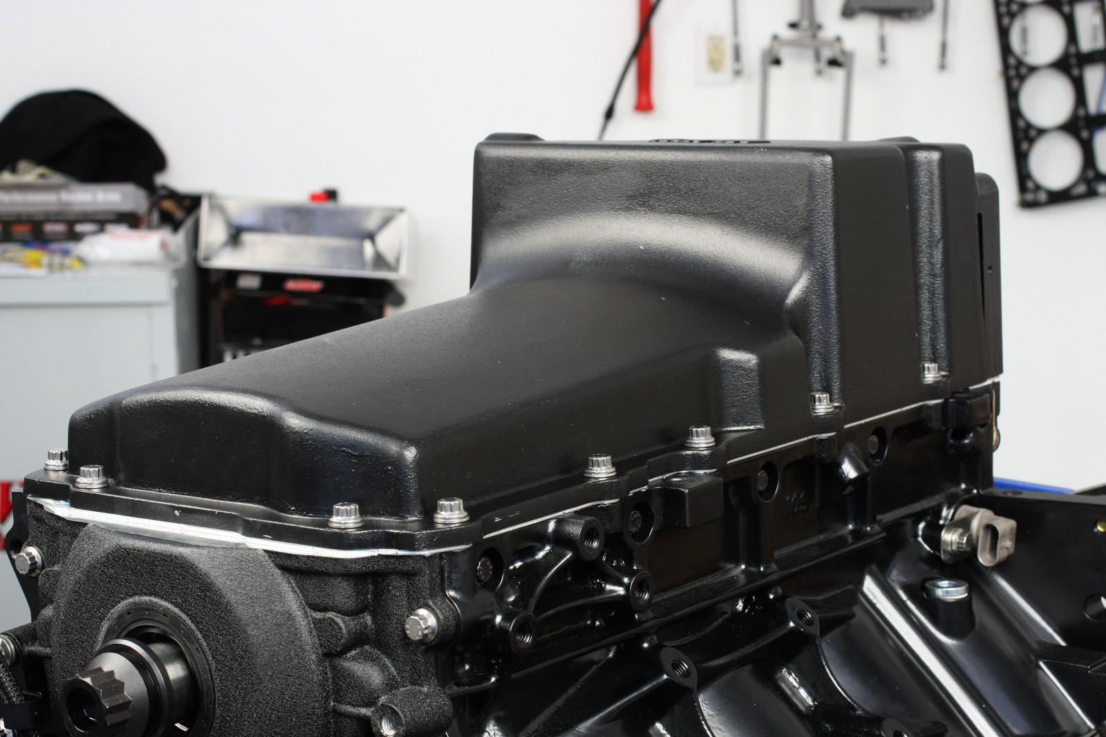
We used Holley’s cast aluminum oil pan with a black ceramic coating. The pan features a slightly deeper front pan area that clears a 4.000 inch stroke crank with no rod clearance issues. The Holley pan includes a baffle, pickup tube assembly, oil filter adapter, drain plug, and an oil cooler crossover cover (where an external oil cooler is not planned). The oil drain plug hole features a helical insert, which is a nice touch. Holley specifies an AC Delco PF48, Wix 57060, Mobil 1 M1-113, or equivalent oil filter for use with this pan.
Recommended oil pump pickup screen-to-sump-bottom clearance is 3/16 to 1/2 inch. The Melling oil pump includes two O-ring seals for the pickup-to-pump mount to accommodate different pickup tube designs. We used the thinner black O-ring with our Holley pickup tube.
The oil pan mounts to the block and front cover with twelve 8mm ARP bolts and flat washers. It is secured to the rear cover with two 6mm ARP bolts. All 8mm bolts are torqued to 18 ft-.lbs., while the rear 6mm bolts are torqued to 106 in.-lbs. Hole alignment on both the Fel-Pro gasket and Holley pan were dead-on, with no need to modify any pan holes. The pan’s oil cooler ports were covered with the supplied crossover housing, a Fel-Pro gasket, and two ARP 6mm bolts.
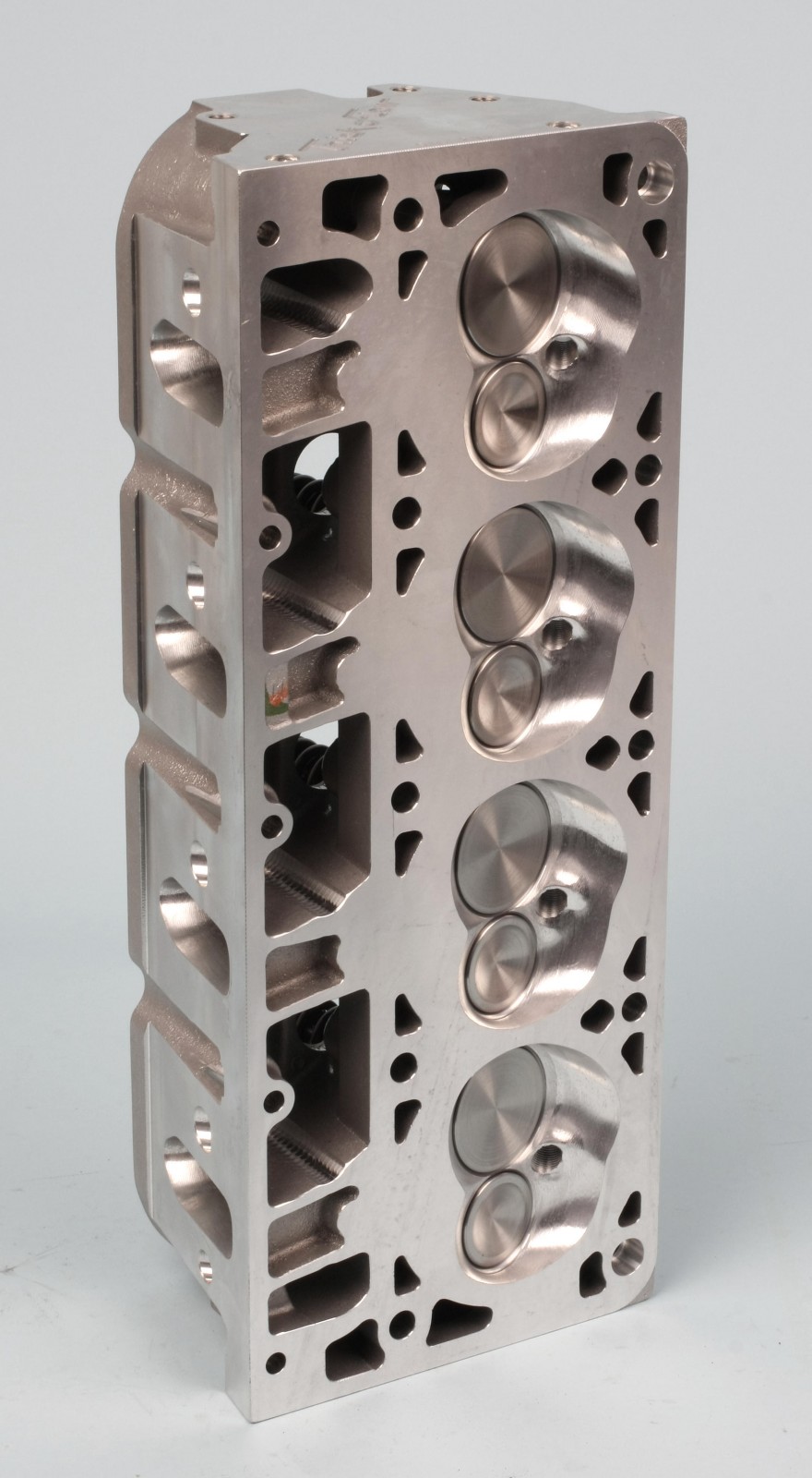
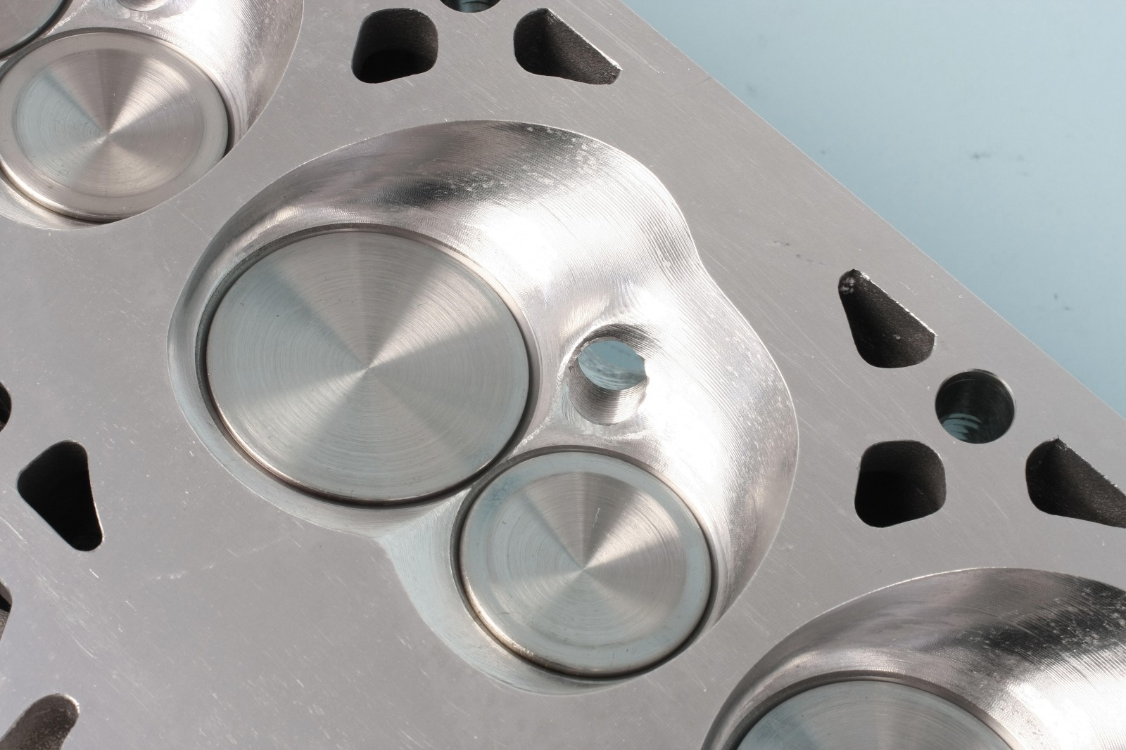
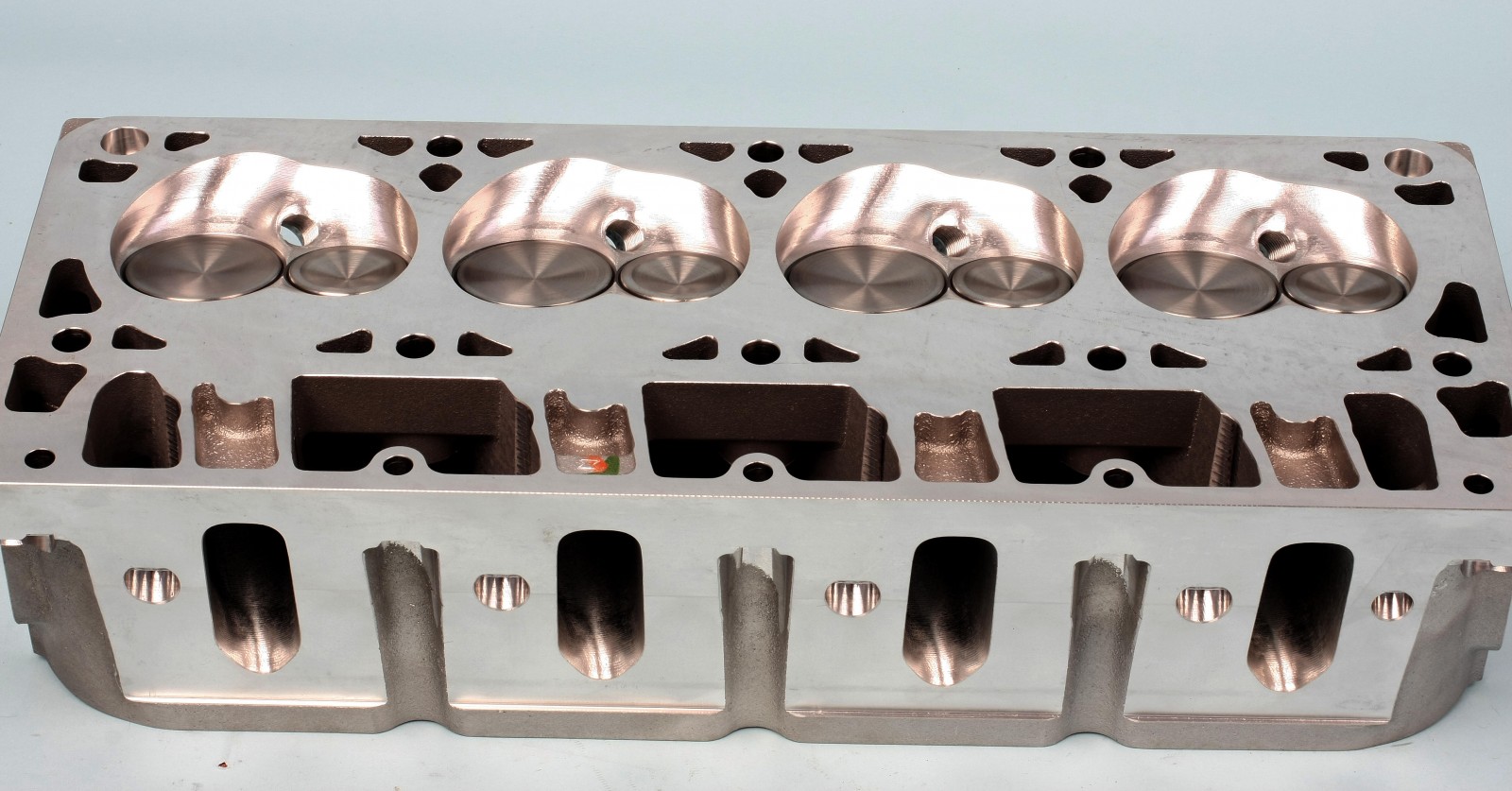
Cylinder Heads
The Trick Flow GenX® 225 aluminum cylinder heads feature 225cc intake/80cc exhaust runners and 65cc combustion chambers with Trick Flow’s full CNC Competition porting and chamber machining. Features include 2.055-inch intake/1.575-inch exhaust valves, dual 1.300-inch valve springs, titanium retainers, and seven degree locks. Trick Flow changed the valve angle from 15 degrees to 13.5 degrees to decrease valve shrouding, increase mid-lift airflow, and improve rocker arm-to-valve cover clearance. Material was also added at the rocker arm mounting points for increased high-rpm valvetrain stability. Spark plugs are angled to enhance mid-lift airflow.
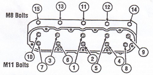
We used Fel-Pro MLS Permatorque head gaskets. Orientation is critical to avoid blocking off water jackets, so each gasket has a prominent “FRONT” imprinted on the top front side. The heads were secured with ARP head studs. Prior to head installation, the 11mm female threads in the block were cleaned using an ARP thread chaser specifically designed for LS blocks. The ten primary head studs were installed finger-snug, with nuts torqued to a final value of 80 ft.-lbs. All threads, washers, and nut undersides were coated with ARP assembly lube. The inboard 8mm “pinch” stud nuts were torqued to 25 ft-.lbs.
In case you’re wondering about our static compression ratio, it ended up at 11.4:1.
Rocker Arms and Pushrods
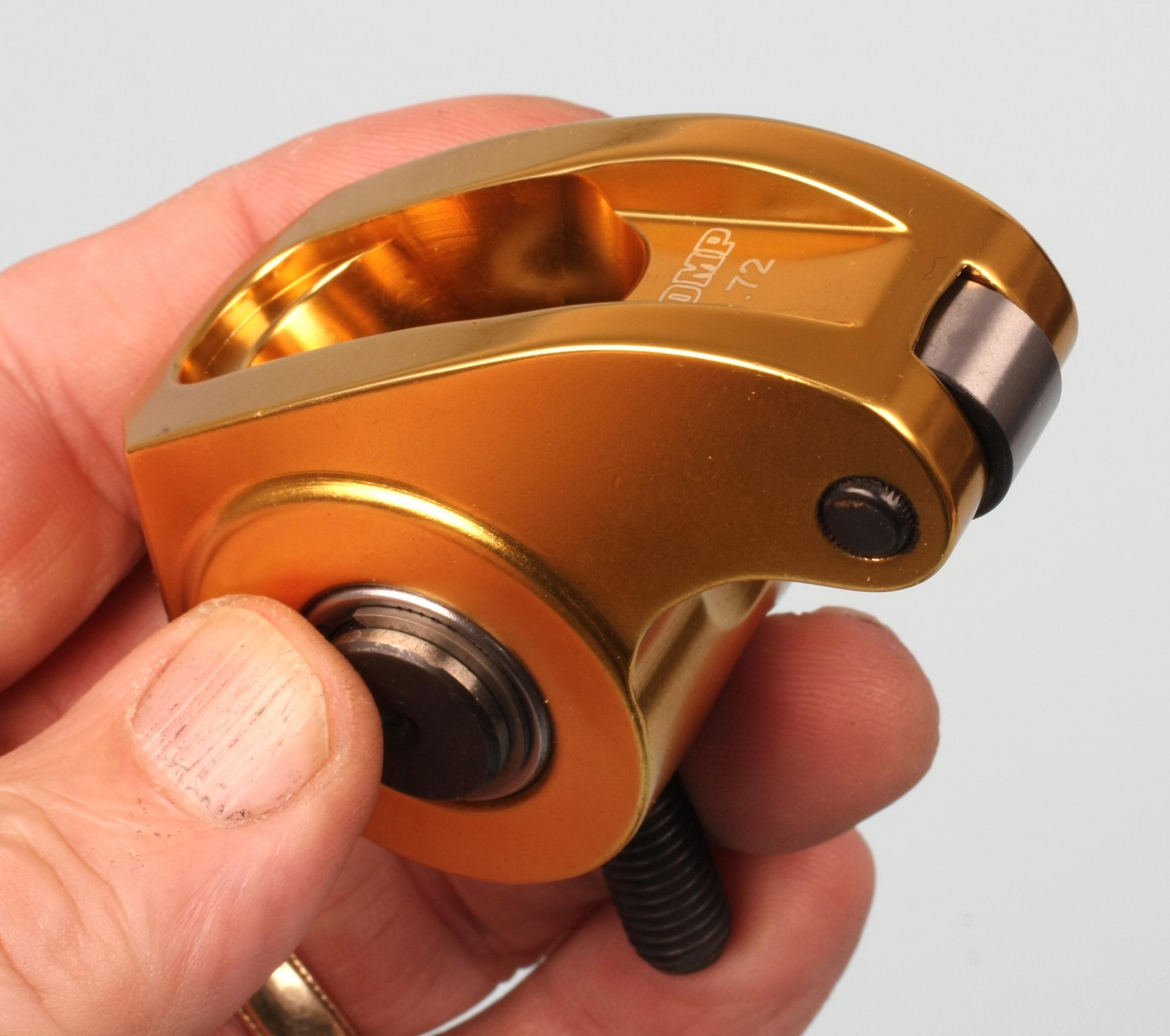
While OEM powder metal rockers used with a trunion upgrade kit would certainly suffice for this build, we wanted to remove the friction factor between the rockers and valve tips. We went whole-hog and stepped up to COMP’s Ultra Gold ARC aluminum full-roller rockers, sticking with the OE ratio of 1.72:1.
When installing rocker bolts on an LS head, you must apply thread sealant to the intake rocker bolts as the threaded holes in the heads are open to the intake runners. Failure to seal these threads will likely result in a vacuum leak.
The rockers are non-adjustable, so pushrod length is critical. We used an adjustable checking pushrod, light checking valve springs, and a hydraulic lifter converted to solid to determine pushrod length. With valve closed and with the checking pushrod adjusted to zero, we measured a length of 7.450-inch. After adding 0.050-inch for lifter preload, final pushrod length came out to 7.500 inches. We used one-piece Elgin 5/16 x 0.110 inch wall pushrods.
With the light checking valve springs and solid lifter in place, we measured valve-to-piston clearance. It measured 0.190-inch on the intake side and 0.143-inch on the exhaust.
Harmonic Damper
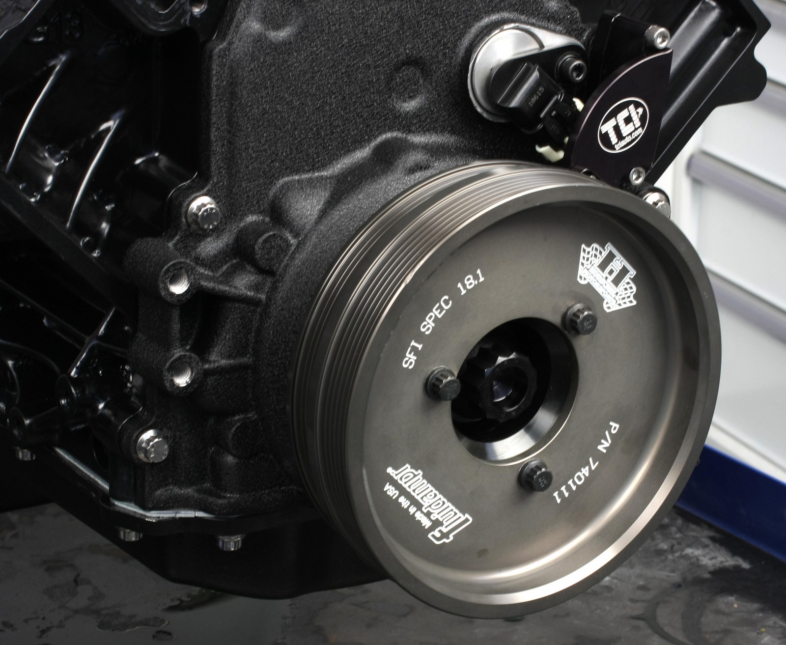
The 7 1/2 inch diameter Fluidampr harmonic damper fits on the crank snout with a 0.0015 inch-plus interference fit. The crank snout was lightly coated with Royal Purple Max Tuff assembly lube, then the damper was carefully drawn onto the snout using a balancer installation tool. The damper was secured with an ARP crankshaft bolt to a final value of 235 ft.-lbs. (with ARP lube). The reusable ARP bolt is much stronger than the OE part and can be tightened directly to a torque value rather than mess with the multi-step OE torque-plus-angle process.
Flywheel Bolts
Be aware that LS crank flange flywheel bolt holes are open to oil, so a thread sealant is required on all flywheel bolt threads. We used ARP flywheel bolts with medium threadlocker sealant on the threads and a light coat of ARP assmebly lube under the bolt heads.
What’s Next
In Part Three of Nighthawk LS, we’ll cover the induction and ignition systems, sensor and water pump installation, and then jump into the dyno room and see what this puppy will do. You won’t want to miss it!
In the meantime, you can begin assembling your own Nighthawk build thanks to special Back in Black Nighthawk combos from Summit Racing.
Comments