See all the articles in this Back in Black Nighthawk LS series here:
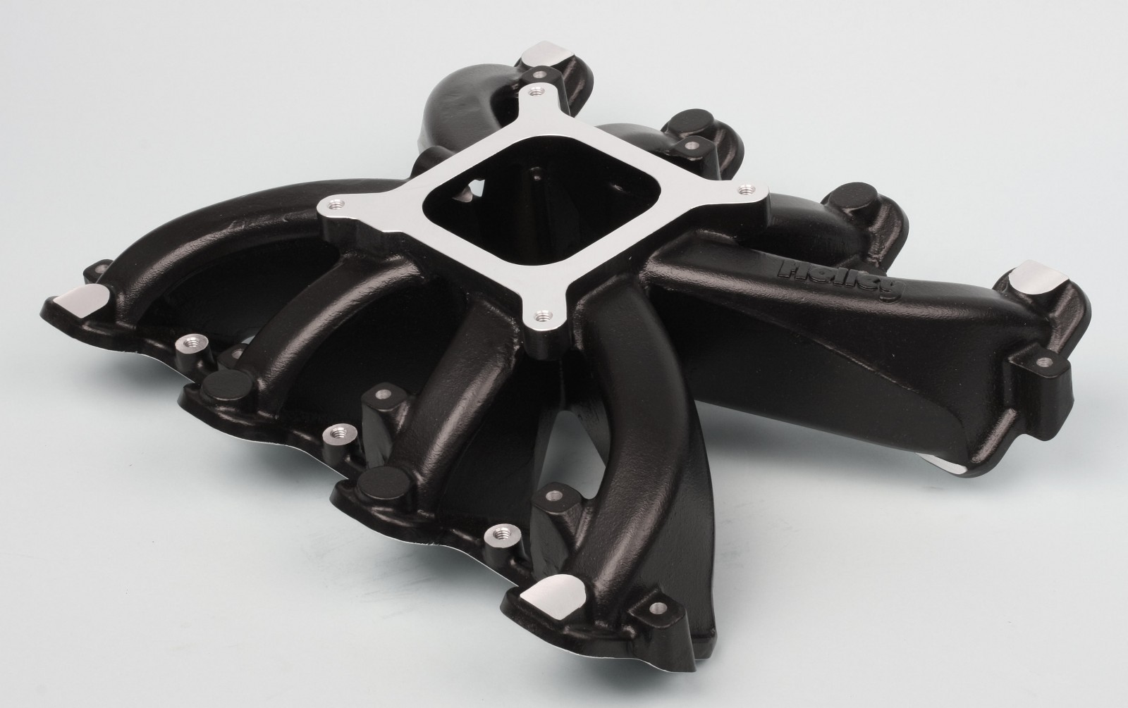
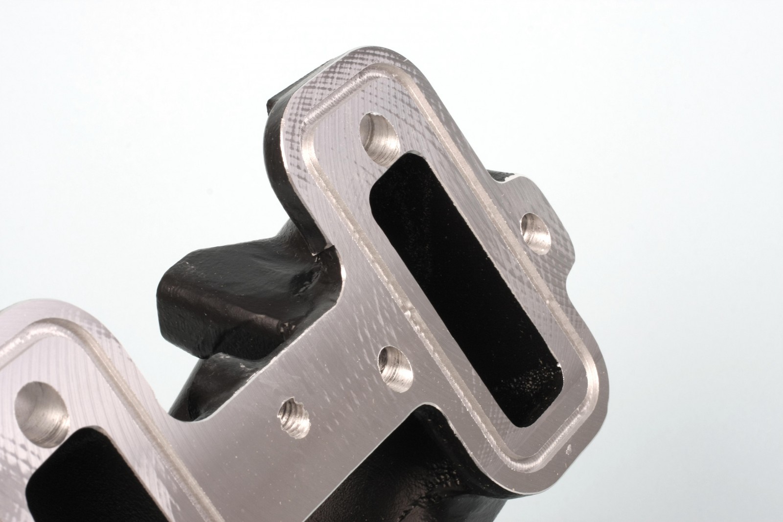


Intake Manifold
Our intake manifold is a Holley four-barrel single plane intake with a black textured ceramic coating. The cathedral ports are sealed with supplied O-ring seals, eliminating the need for traditional intake gaskets. Operating range is 2500-7000 rpm. The intake was secured with ARP polished stainless 12-point bolts and washers.
Fuel Injection
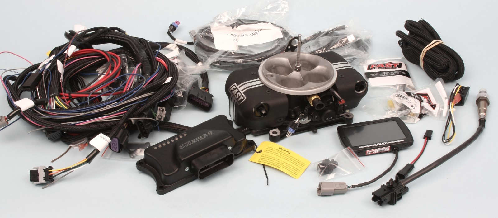
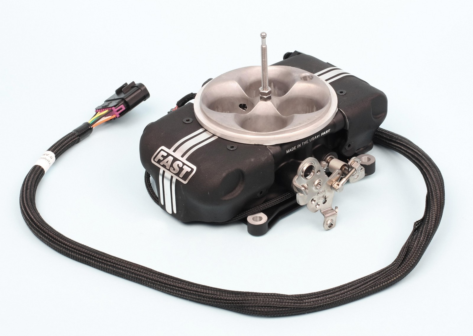
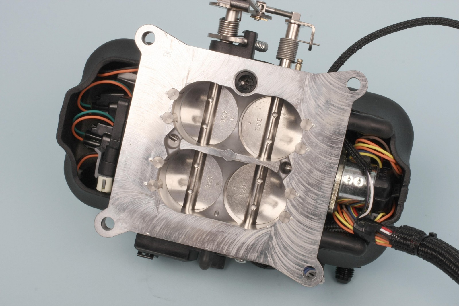
We used FAST’s EZ-EFI 2.0 system on our 408. The throttle body features fuel injectors hidden from view behind faux fuel bowl covers. It also has a built-in throttle position sensor, air temperature sensor, and harness connections for water temperature (labeled CTS for coolant temperature sensor) and the EFI controller. The throttle body is designed for square bore type carbureted intake manifolds.
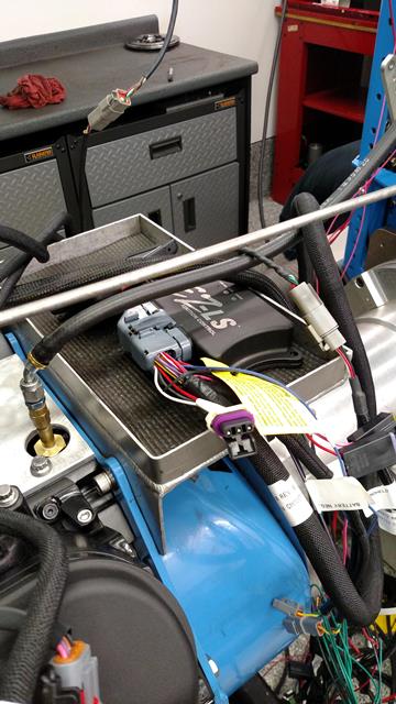
Ignition Controller
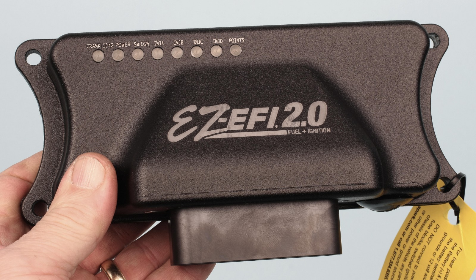
Running a carb on an LS engine only requires a MSD 6LS or 6LS2 ignition control module (depending on reluctor tooth count) and harness. Since we’re running EFI, we used a FAST ignition controller to control both fuel and spark. The multi-connection wiring harness looked intimidating, but the supplied instructions (yes, we actually read them) made things much easier than we first thought. The EFI main harness includes several connections that we don’t need on on the dyno (fans, crank trigger, etc.). For in-vehicle installation, just about every connection that could be needed is included.
The FAST ignition controller harness has a connector for the cam sensor and a separate adapter cam sensor harness. You use one or another depending on the cam sensor you have. In our case we used the sensor adapter harness plugged directly to the sensor. The harness’s crank position sensor connector plugged into our crank sensor with no hassle.
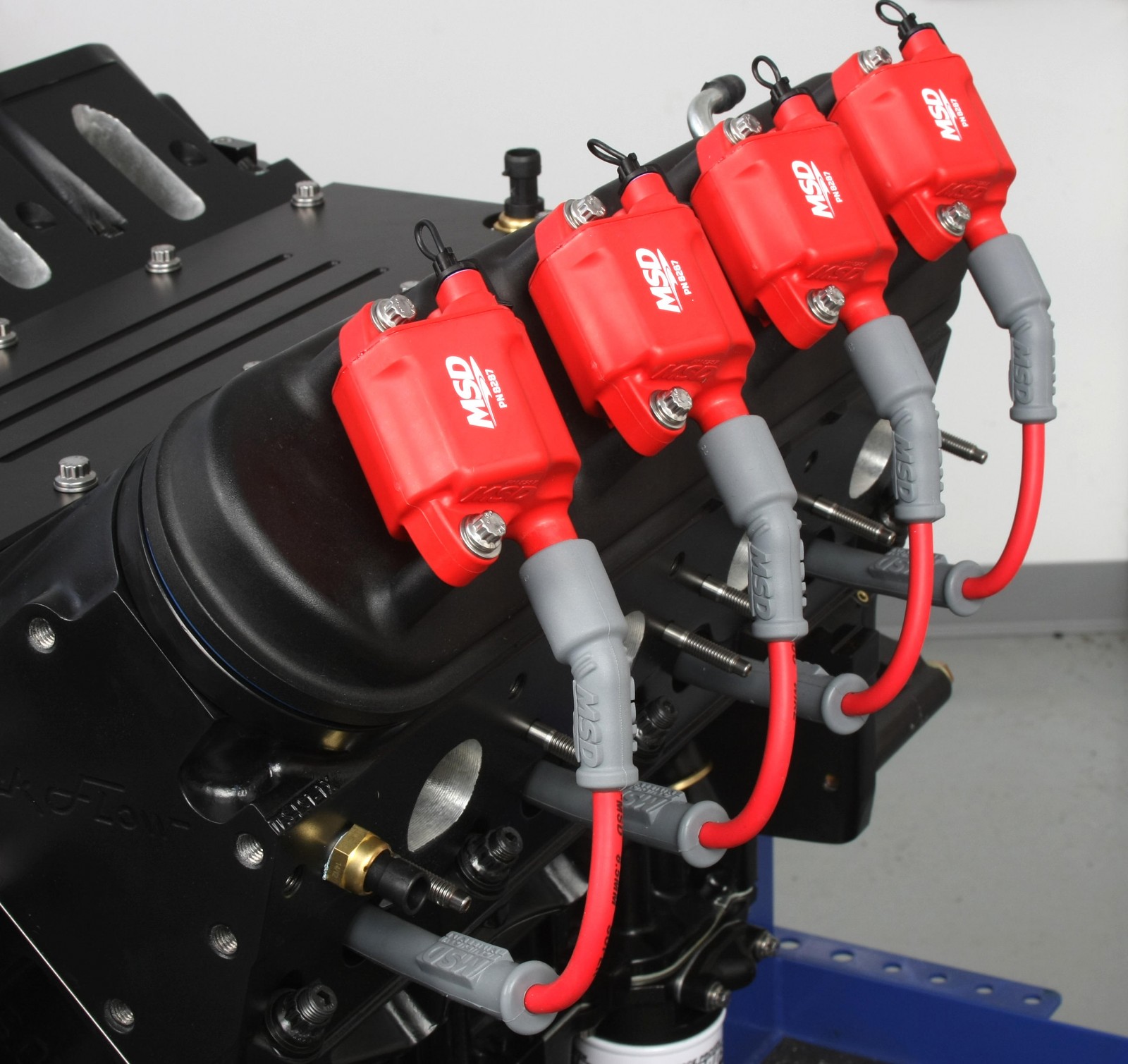
Spark Plugs, Coil Packs, and Wires
Trick Flow recommends NGK-4177 spark plugs for their GenX cylinder heads.We gapped these at 0.050-inch. We used MSD coil packs that fit 2005-2013 LS2/LS3/LS7/LS9 engines. Regardless of which spark controller is being used, you’ll need an OE coil harness to connect the coils to the main controller harness. We purchased two coil harnesses, one for each bank.
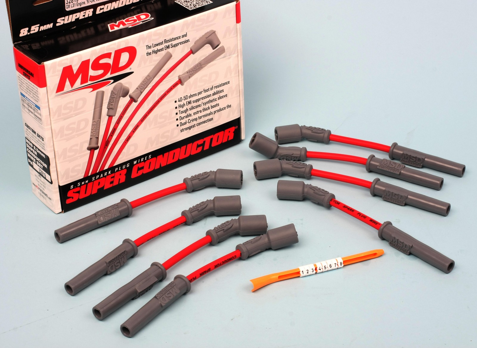
The plug wires are MSD’s Super Conductors. We applied a dab of dielectric grease to the inside of all coil and spark plug boots prior to installation.
Sensors
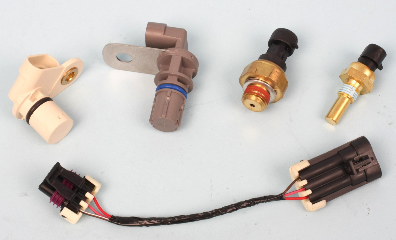
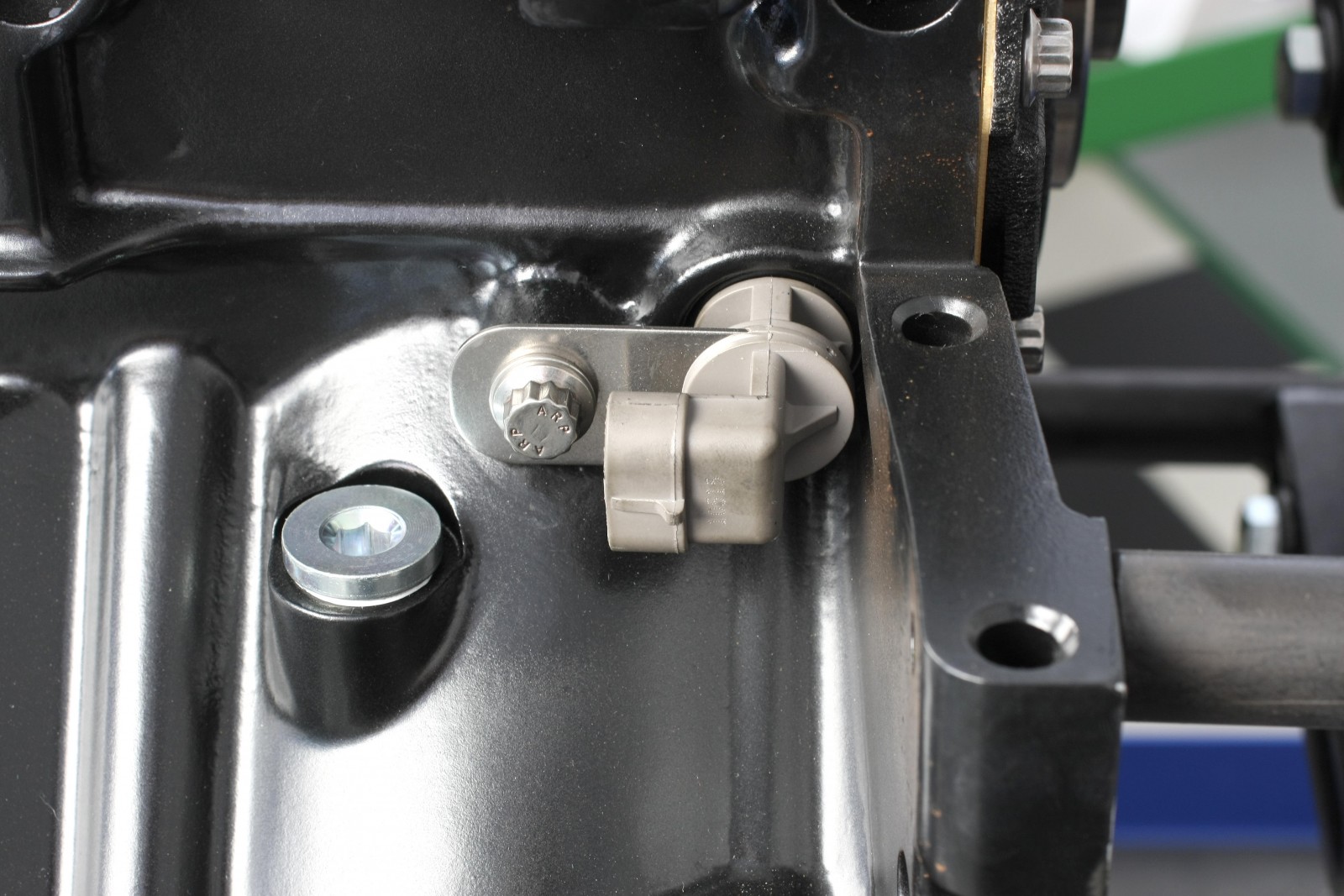
We used Standard Motor sensors on the engine: a water temperature sensor installed to the forward exhaust deck of the left hand head; a camshaft position sensor installed on the front cover; an oil pressure sensor at the top rear of the valley deck; and a crankshaft position sensor installed at the right rear of the block side. Since the left and right cylinder heads are identical, the unused threaded water hole on the right head must be plugged with a 12 x 1.5 x 16mm bolt and sealing washer.
For the dyno, we removed the oil pressure sensor and monitored oil pressure via an Auto Meter brass adapter (ATM-2268) attached to the dyno’s oil line. The adapter has a 16mm x 1.5 male thread and a 1/8-inch NPT female threaded hole.
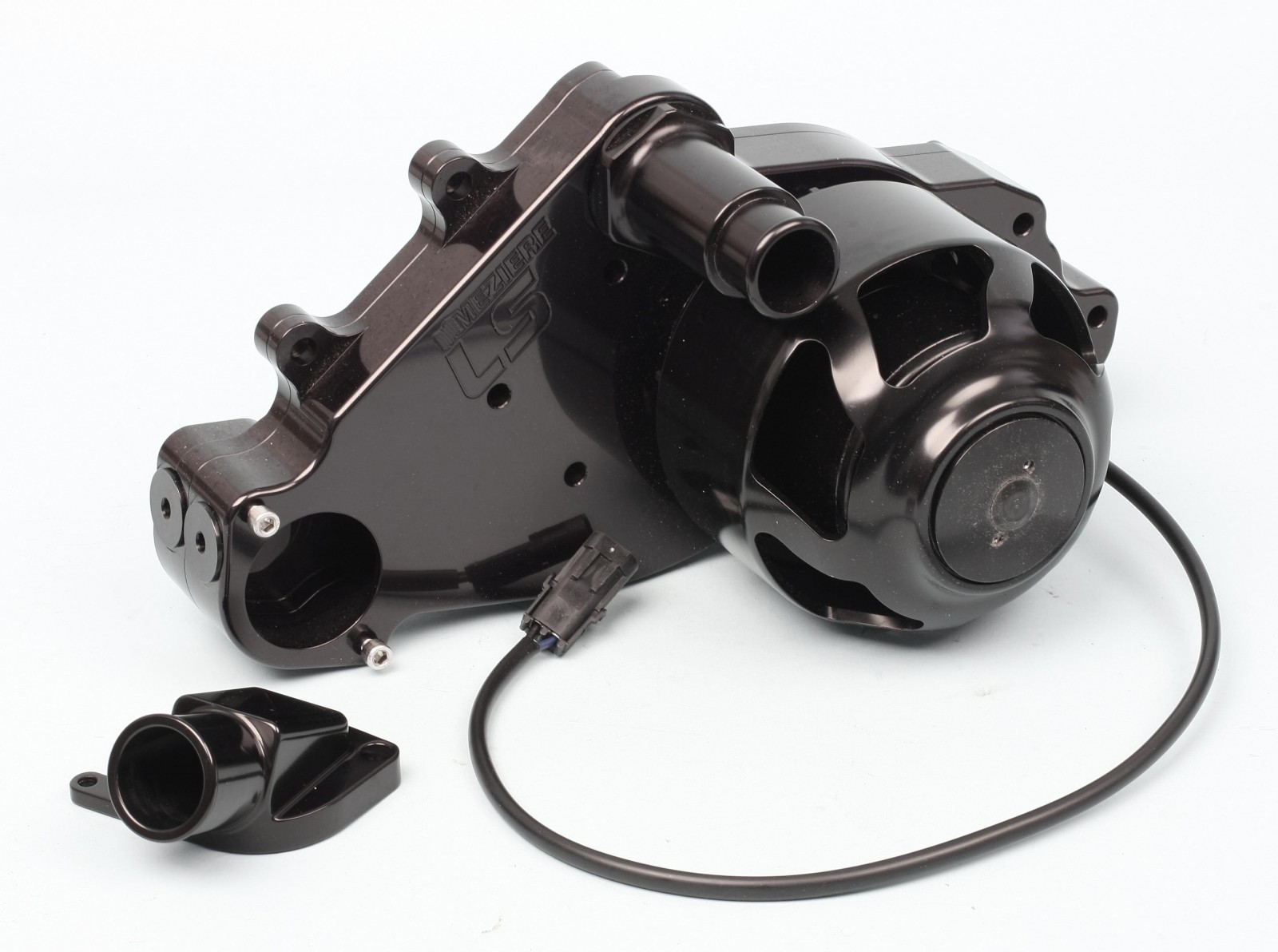
Water Pump
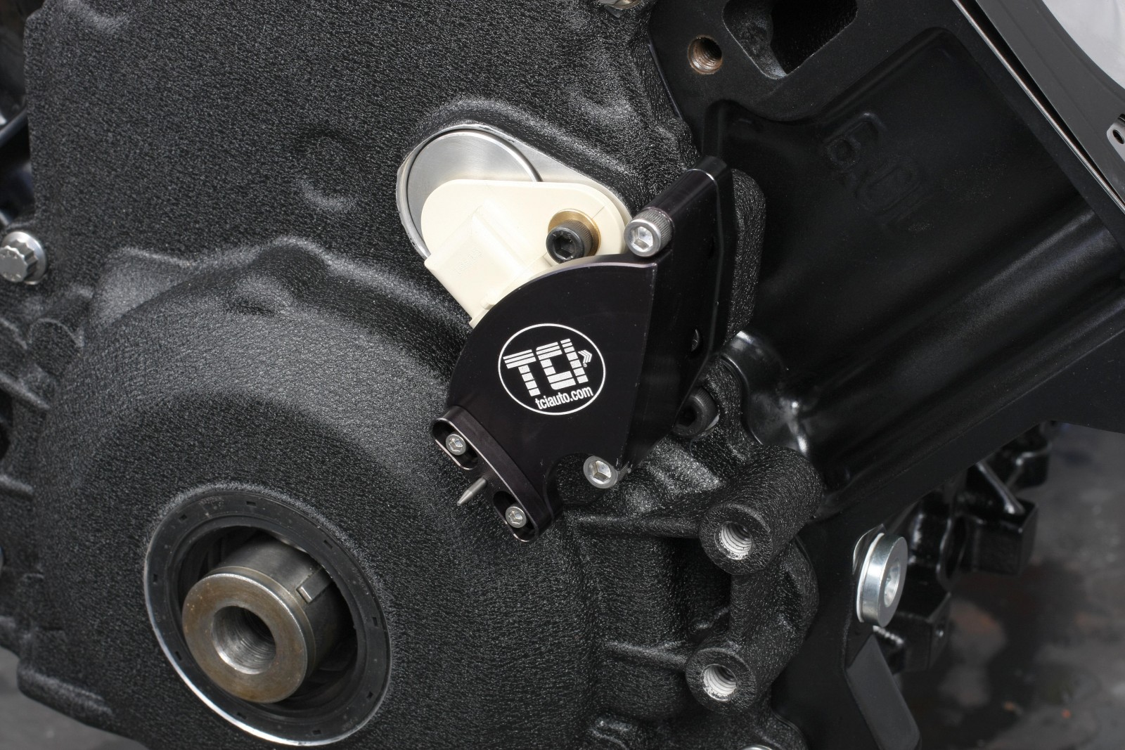
We used a Meziere electric water pump. Using a COMP Cams front cover with this pump produced slight interference between the back of the pump and the inboard edge of the cover’s cam sensor bung. If the pump rocks a bit when you install it, do not try to force it on by tightening the bolts.
To get the pump to mate flush with the block, we ground about 1/8-inch off the inboard edge of the cover’s cam sensor bung lip at about the 10 to 11 o’clock position. You may need to chamfer-grind a bit of material from the back edge of the pump body where it contacts this sensor bung protrusion. A chamfer about one inch long, 1/4-inch wide, and about 1/8-inch deep eliminates the interference. The grinding areas will not be visible once the pump is installed.
Valve Covers
The Holley valve covers are cast aluminum and finished with a black ceramic coating. The covers are factory height and the COMP Cams roller rockers contact the valve cover baffles. Rather than cutting the baffles out, we installed aftermarket half-inch thick billet aluminum spacers to provide adequate rocker clearance. The spacers we used feature a machined groove on the bottom to accept an O-ring sealing strip (included). Instead of using the supplied hex head bolts, we installed the covers with ARP polished stainless 12-point bolts. You’ll need a set of Fel Pro valve cover rubber grommets (FEL-ES72233).
The billet aluminum oil fill cap provided with the Holley valve covers looks like it won’t clear the number two coil pack, but it does by about 0.060-inch. Holley even provides an offset coil mounting bracket for the number two coil that kicks the coil rearward for compressor clearance on vehicles with air conditioning.
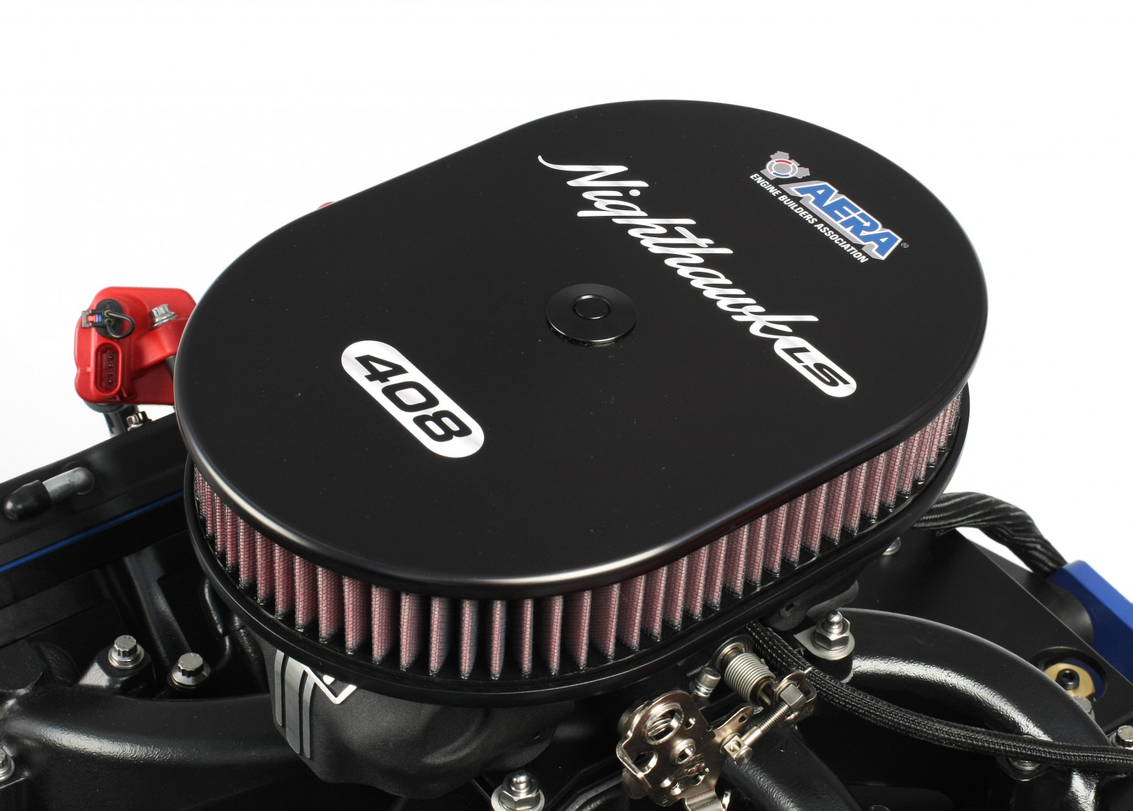
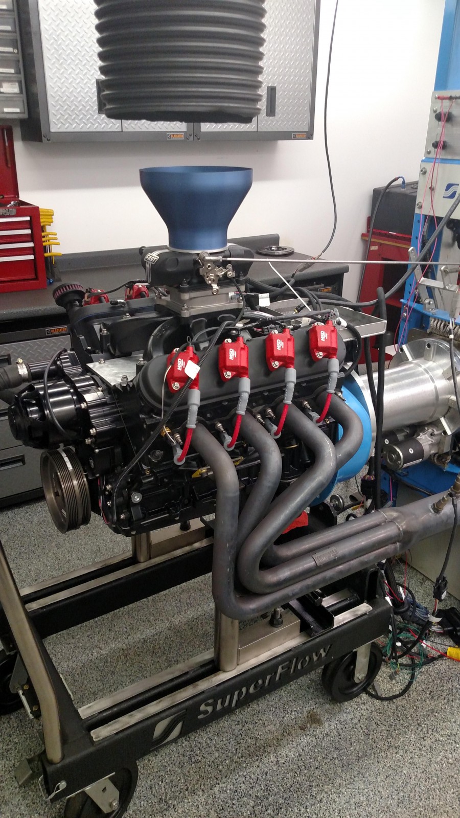
Air Cleaner
We had a particular air cleaner design in mind for this engine. We based it on a Billet Specialties oval air cleaner assembly. It measures 11 7/8 x 8 7/8 inches and features a machined 6061 aluminum top. We enlarged the center mounting hole to 0.750-inch to accommodate a very cool quick-latch push-button retainer/release system from S&W Race Cars. Rather than messing around with a traditional nut or knob, you simply press the spring-loaded button to pop the top off; to lock it back in place, push the top on until it clicks and locks.
To prevent the air cleaner base from rotating too easily, we fabricated a small billet aluminum “key” that features a flat-to-flat square base. This secures to the top of the right side of the throttle body with a 8-32 stainless flat-top screw. We machined a 6mm peg that projects out horizontally on the right side, then filed a U-shaped groove in the air cleaner base lip to engage the peg. This provides a “register” for the air cleaner so top and base stay aligned.
We swapped out the air cleaner’s white filter element for a red K&N filter so it would be better color-coordinated with the rest of the engine.
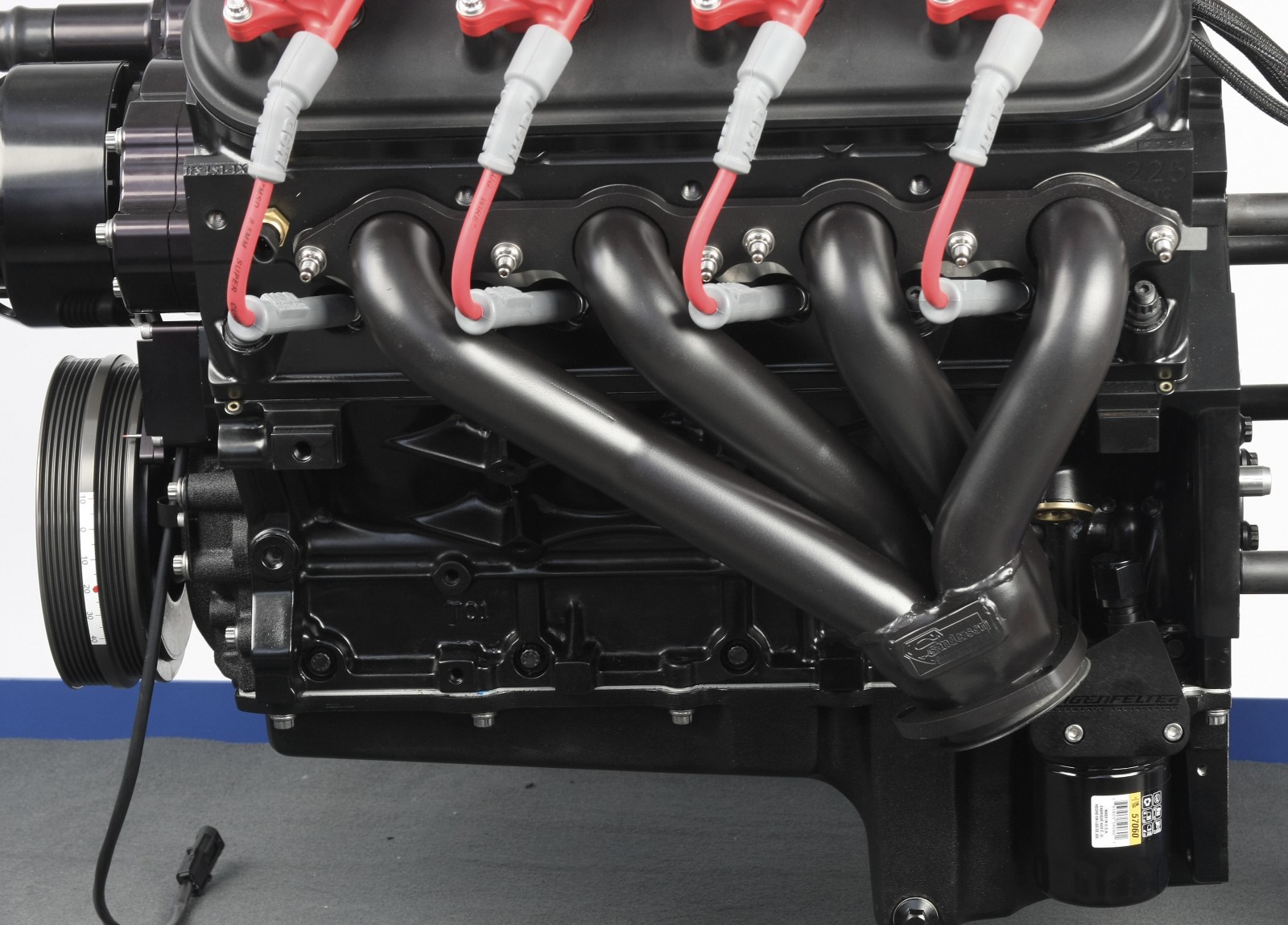
Headers
We used the dyno shop’s headers equipped with air ratio sensors during testing. We installed a set of Sanderson headers for photo and display purposes. The headers feature include 16-gauge tubing, 1.75-inch primary tubes, three inch and 3/8-inch thick flanges. They also have a patented flange design that seals without the use of gaskets. The headers had no clearance issues whatsoever, with no-hassle access to all spark plugs.
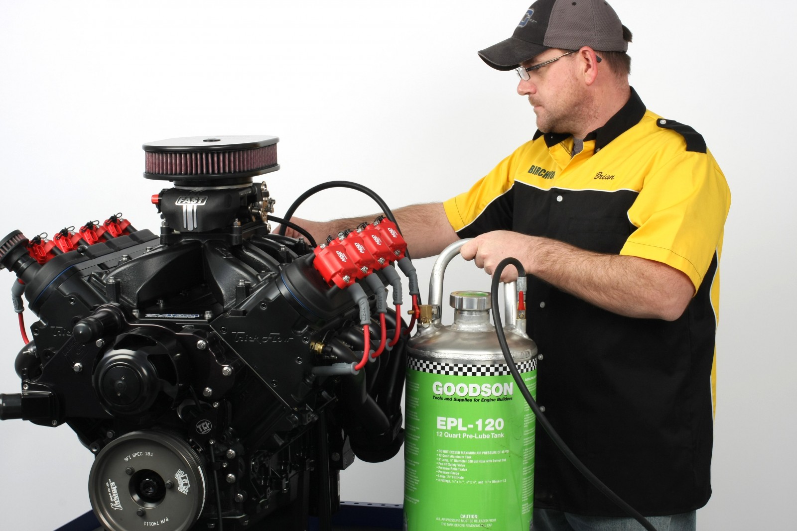
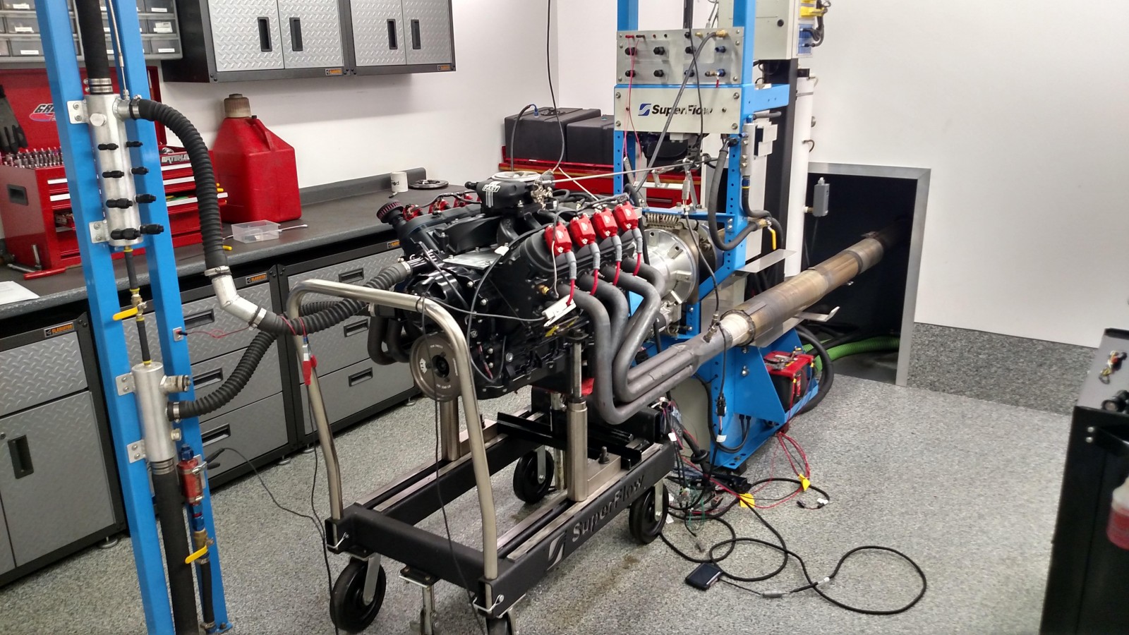
Dyno Run and Results
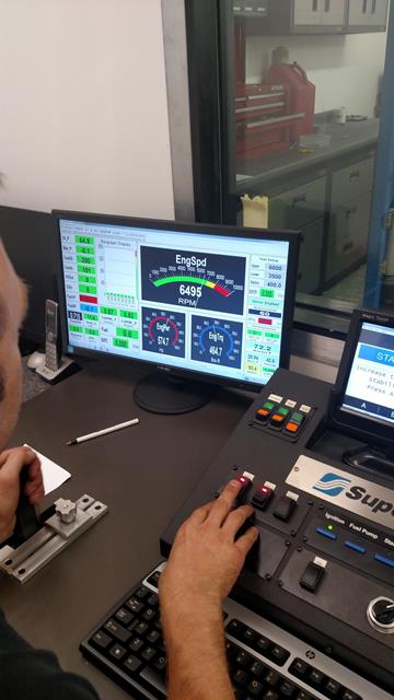
The engine was dyno tested at Gressman Powersports in Fremont, OH, down the road from my shop. Prior to the dyno run, we pre-oiled the engine using a pre-oiler tank. This insures that oil has been distributed under pressure through all oil passages prior to initial startup.
While the FAST EZ ignition control system is LS-dedicated, the EFI system itself is a universal design that works on most any V8 engine. Time and patience is required to determine which connectors you actually need to use for a given application. Plan to spend some time reading the EFI instructions before blindly plodding ahead.
We connected the coil harness to the coils and plugged these into the FAST EZ ignition controller harness. The FAST ignition and EFI controllers and harnesses were then installed. Each connector is labeled, but the EFI harness features quite a few connectors that we didn’t need (electric fan control, crank trigger, etc.). We had to lengthen the water temperature sensor harness from the throttle body as it was about six inches too short to connect to the cylinder head-mounted temperature sensor.
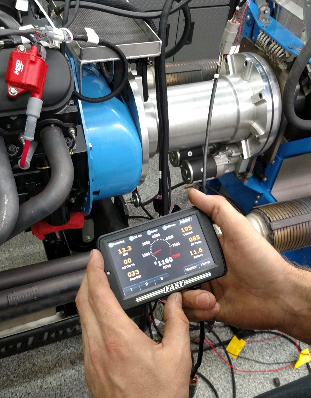
We used the FAST system’s hand-held touch-screen for initial setup. The setup wizard is actually quite easy to use. The engine fired and ran flawlessly through four pulls. Oil pressure ranged from 41 to 61 psi, depending on engine speed. Initial timing was set at 21 degrees. We suspect playing with more timing would gain more power, but we had limited time on the dyno so we really didn’t have the luxury of extensive experimentation.
Our best pull yielded 629.5 peak horsepower at 6,500 rpm and 555.6 ft-.lbs. peak torque at 5,100 rpm. The 408’s throttle response was scary quick. Every time Scott Gressman blipped the throttle, the faces of everyone in the control room morphed into a huge grin of delight. In Scott’s words, “it sounds like a real baddass mutha.”
As a quick experiment, we added a two-inch tall carb spacer and picked up 10 more horses between 6,500 and 6,800 rpm. We definitely feel that there’s a bit more to be had once the FAST EZ EFI system “learns” the engine more. A taller intake manifold with longer runners would also help gain additional power at top end.
NightHawk LS 408 Dyno Run
RPM Torque (Ft.-Lbs.) HP
3600 466.8 340.0
3700 473.5 355.3
3800 494.7 374.9
3900 508.8 391.4
4000 516.8 407.8
4100 524.6 426.1
4200 534.9 443.1
4300 539.7 463.0
4400 543.0 482.5
4500 548.6 496.8
4600 552.8 510.1
4700 554.0 522.8
4800 554.9 535.3
4900 555.0 546.8
5000 555.5 558.5
5100 555.6 570.0
5200 555.0 580.7
5300 552.0 588.5
5400 549.8 594.7
5500 547.1 600.5
5600 544.9 605.6
5700 540.0 609.0
5800 537.3 611.0
5900 532.6 612.4
6000 527.5 619.5
6100 524.2 623.7
6200 520.2 625.8
6300 511.9 628.6
6400 508.4 629.0
6500 502.9 629.5
6600 489.4 628.6
6700 479.7 625.3
6800 472.7 623.3
Which trickflow heads were use in the back in black nighthawk build
Hey Calvin – Sorry for the delay, but those are Trick Flow® GenX® 225 Cylinder Heads for GM LS2. Click here to check them out.
where is part 1 to this build? I would like a complete build sheet for this engine.
Hey Seth – Sorry about that, looks like there was a glitch in our Matrix.
…
But we were able to fix it. CLICK HERE to see Part One of our Nighthawk LS series.