Valvetrain geometry can be a finicky thing in pushrod V8 engines, especially when aftermarket heads, cam, lifters, and valvetrain are added to the mix. Sometimes you get lucky and everything just bolts right up and the geometry works without much fuss.
And of course, sometimes, it doesn’t.
Assuming you’ve got the right parts and the correct pushrod length, one of the most common geometry issues that can arise is misalignment of the rocker arms on the valve stem. This usually occurs on aftermarket cylinder heads with larger runner sizes or different valve spacing that shifts the pushrod position. It doesn’t take much shifting to exceed the ability of a standard one-piece guide plate to align both rockers.
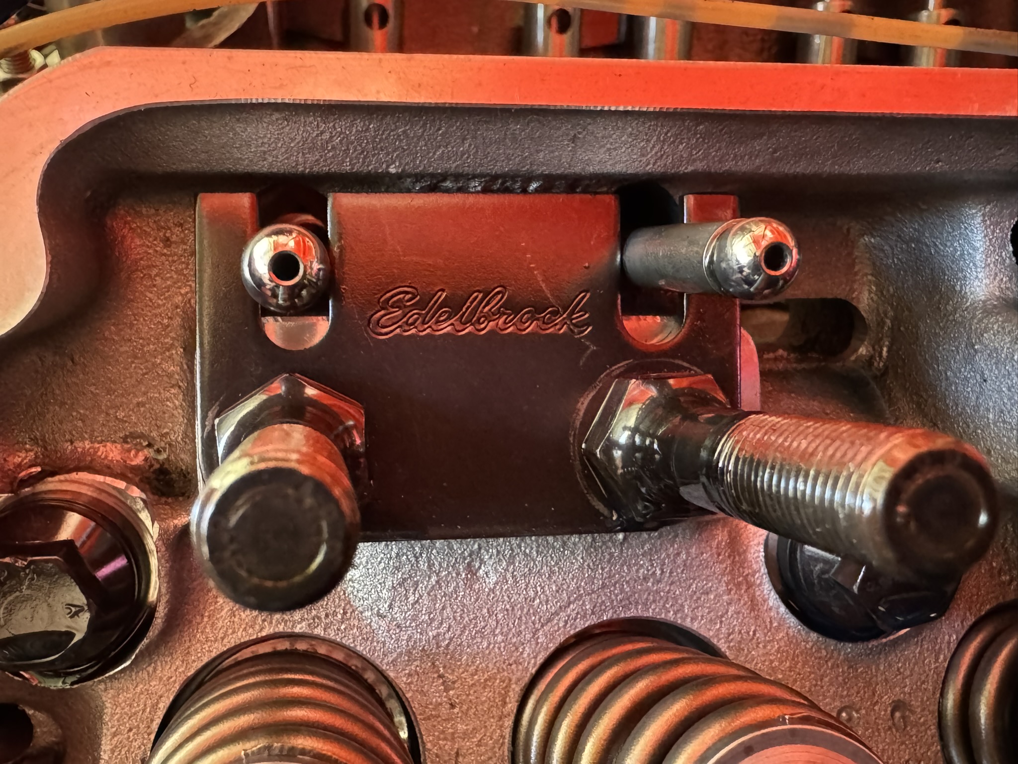
It doesn’t just happen with high end race parts either. We ran into this issue with one of our Ford 351 Windsor builds that is utilizing a complete Edelbrock cam and top end package. The standard single piece guide plates did not have enough lateral movement to allow both of our rocker arms to align nicely on the valve tips.
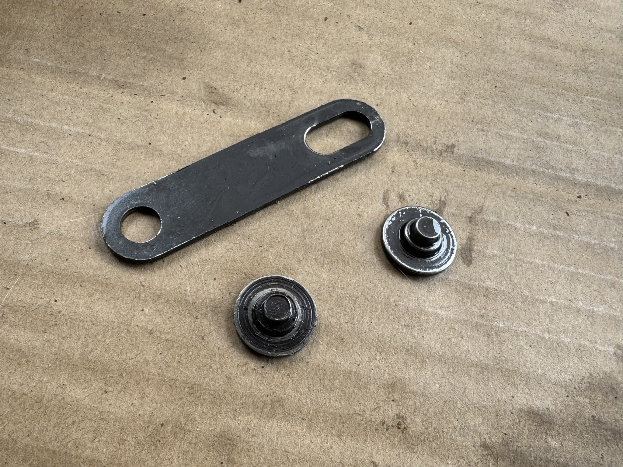
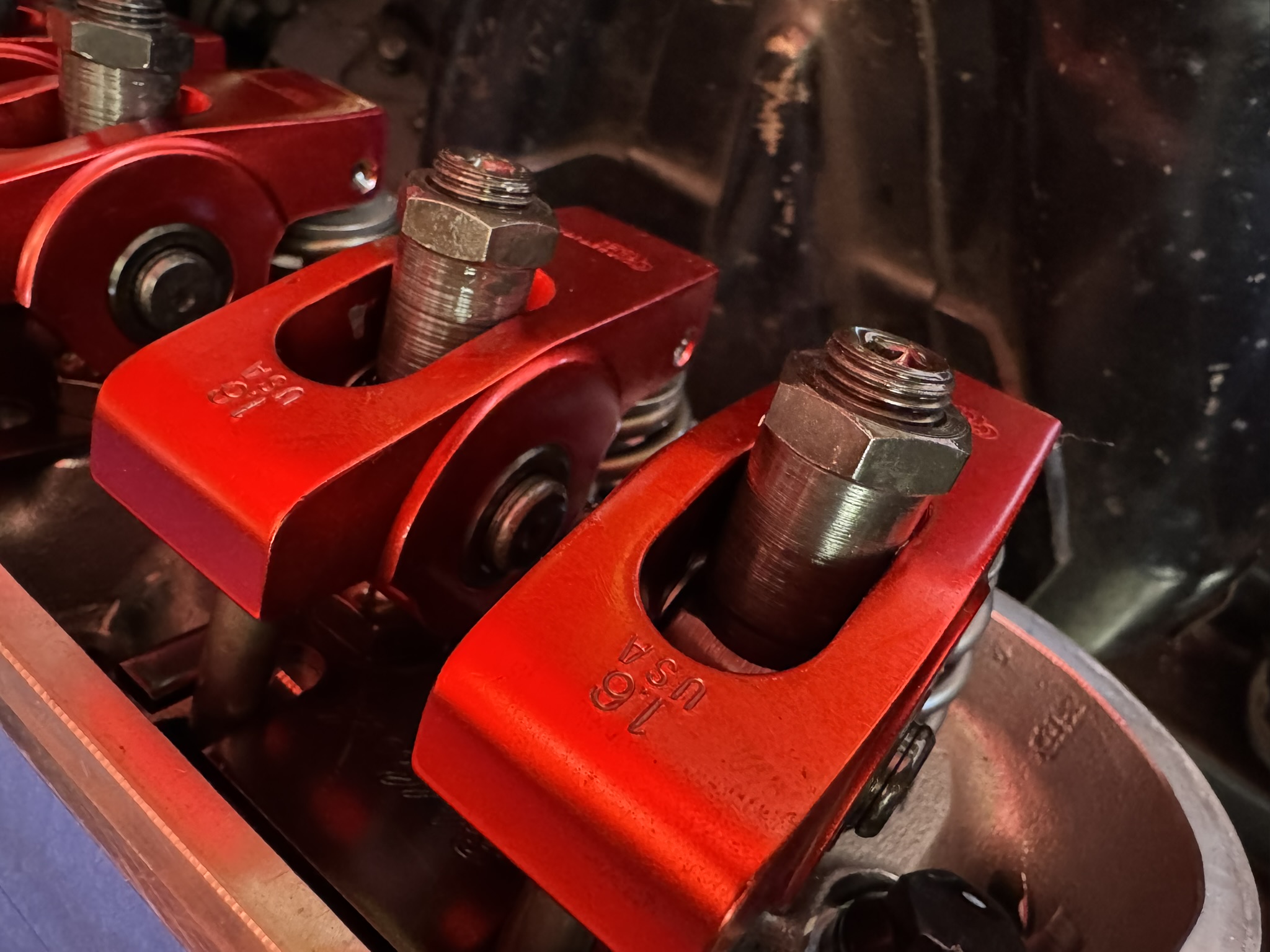
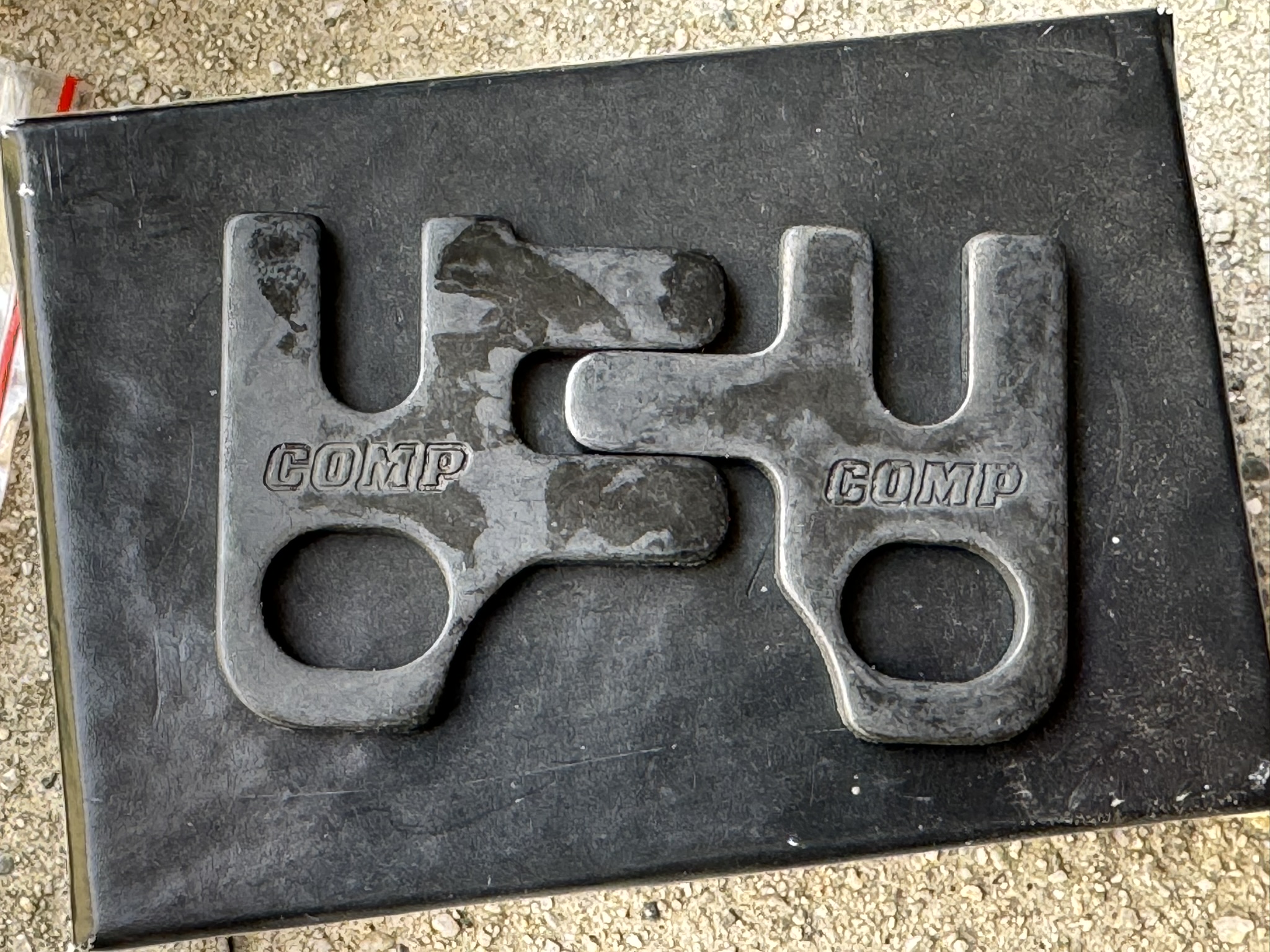
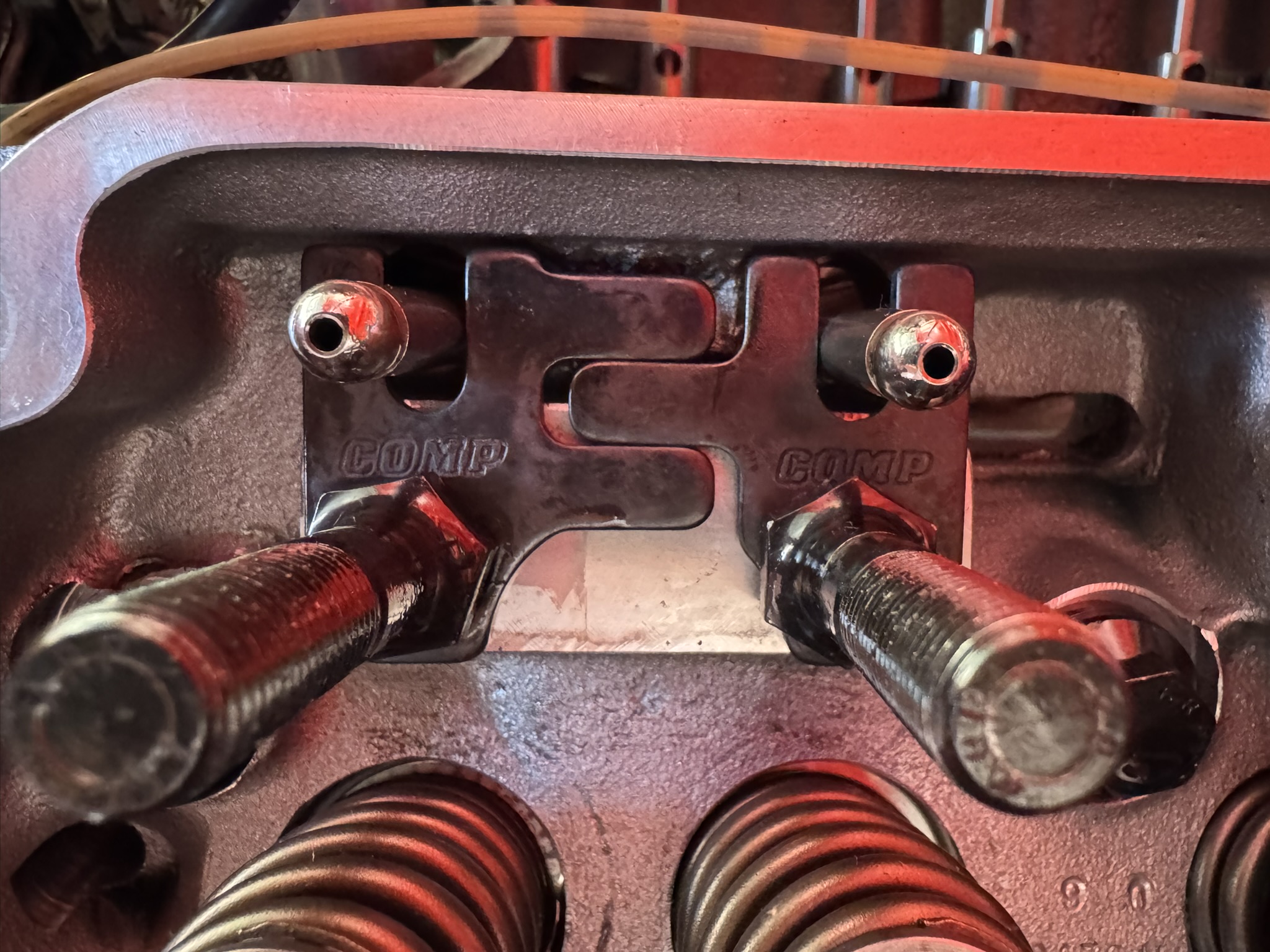
To address this common issue, COMP Cams developed a line of adjustable guide plates, including a sliding two-piece sets that works for both small block Chevy and small block Ford engines with 5/16 inch pushrods. Created from precision die-stamped and heat-treated steel, these fully adjustable guide plates feature an interlocking design that enables a reliable and easy adjustment in the one axis needed for most valvetrain misalignments, including our Windsor.
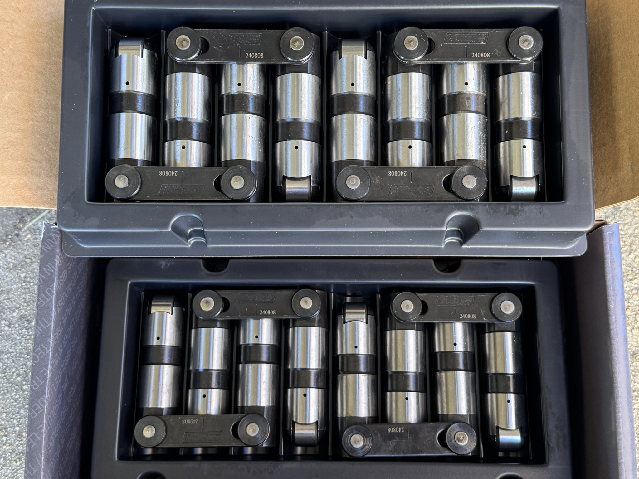
While we’re at it, we’re also swapping in a set of COMP Cams new Evolution hydraulic roller lifters with their revolutionary Hydraulic Cartridge Technology since we noticed one of our lifter link bars somehow managed to detach itself. Talk about fortunate timing since we’re pulling everything apart anyways.
We know disassembling your valvetrain and installing adjustable guide plates sounds intimidating, even we avoided it for a while. Fortunately, the reality isn’t as bad as you might think. Follow along as we demystify the process and show how you can easily do it at home if your rockers are a little askew.
While we’re working on a 351 Windsor, the process and plates are the same for small block Chevy
The Parts
CCA-4835-8 – COMP Cams Pushrod Guideplates for Small Ford & Chevy
CCA- 89311-16 – COMP Cams Evolution Series Hydraulic Roller Lifters
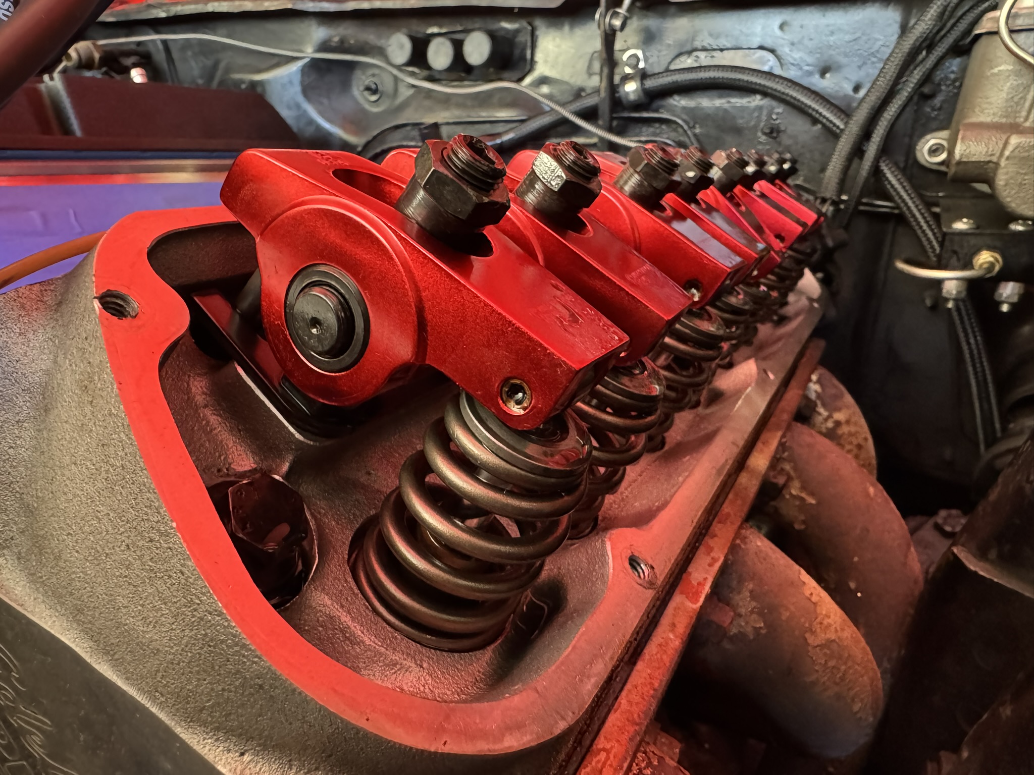
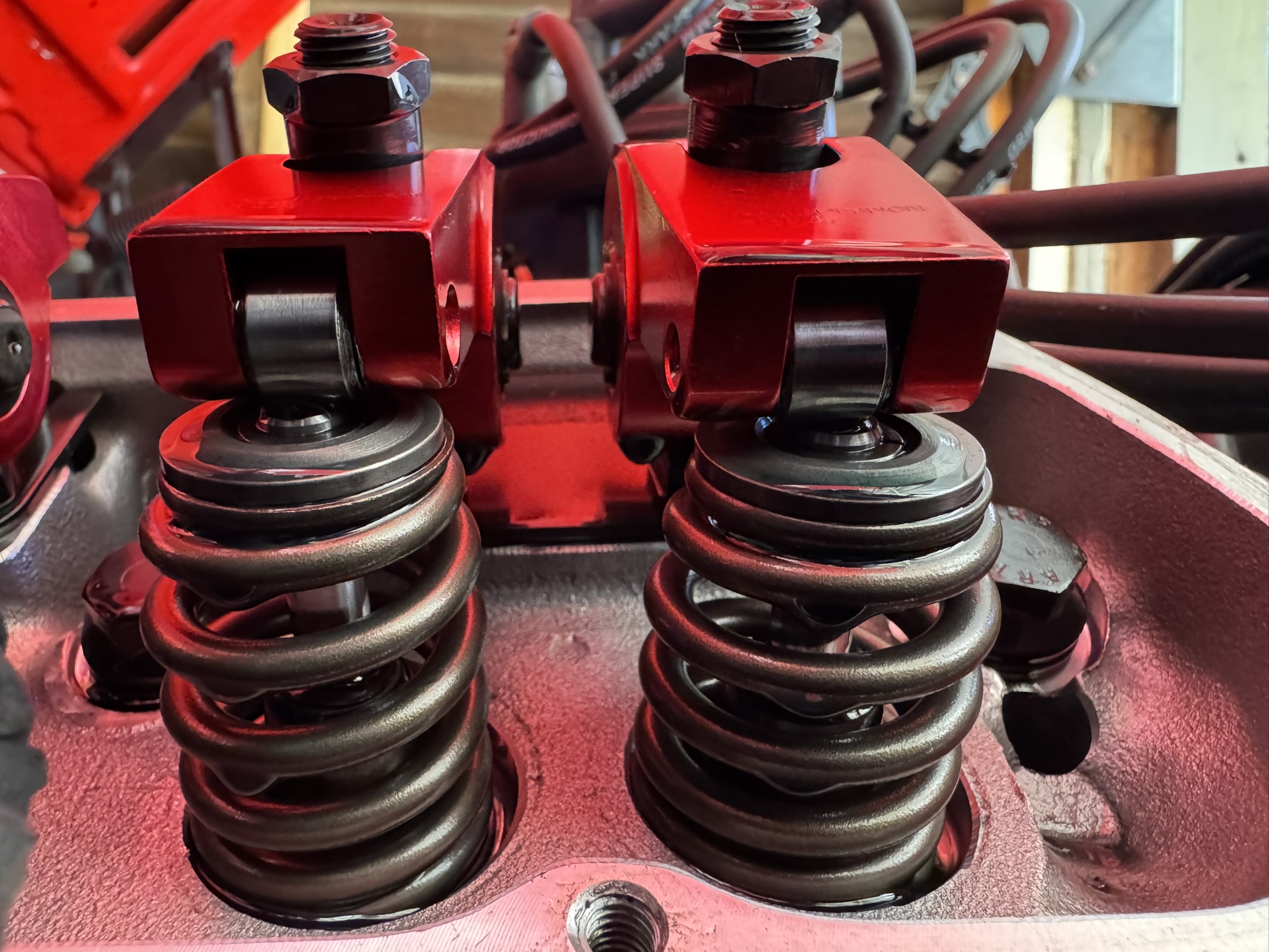
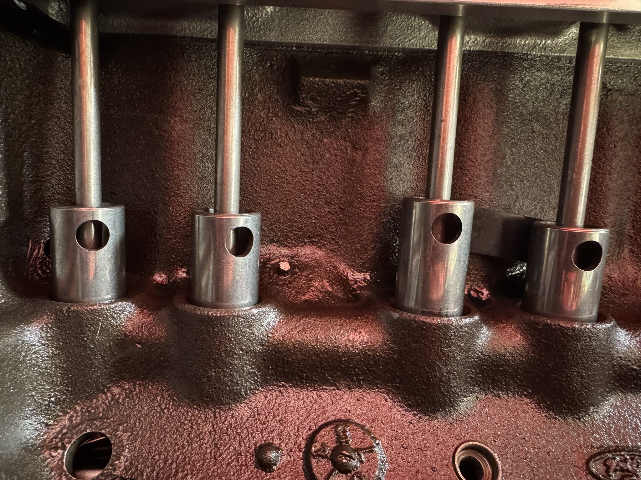
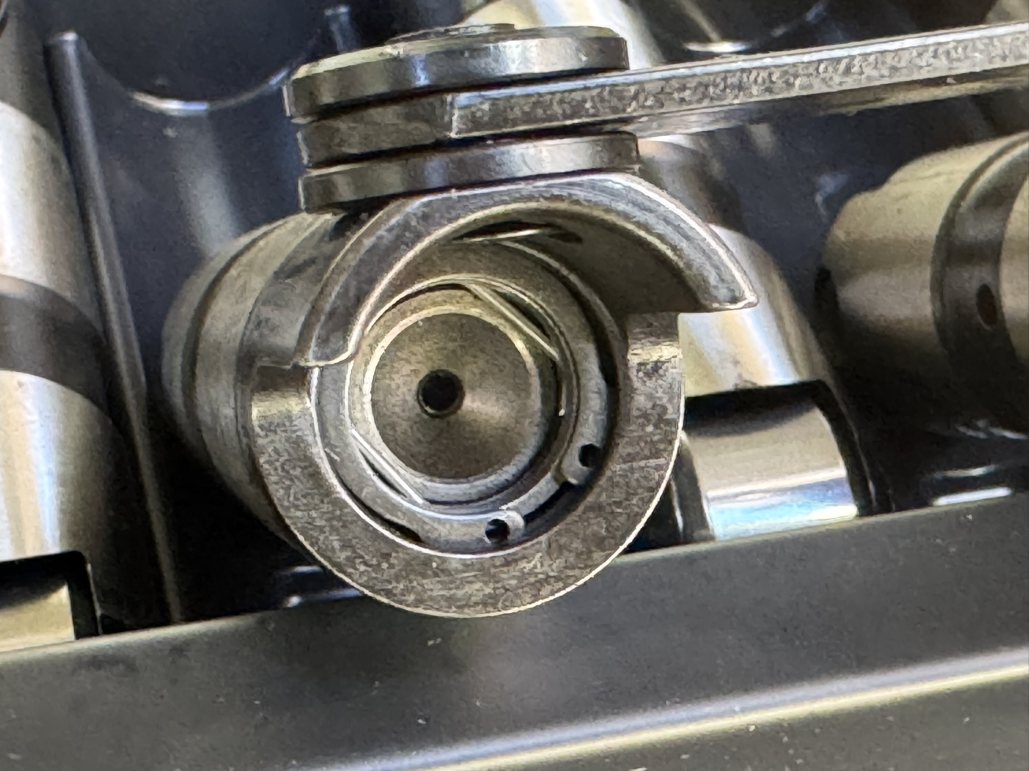
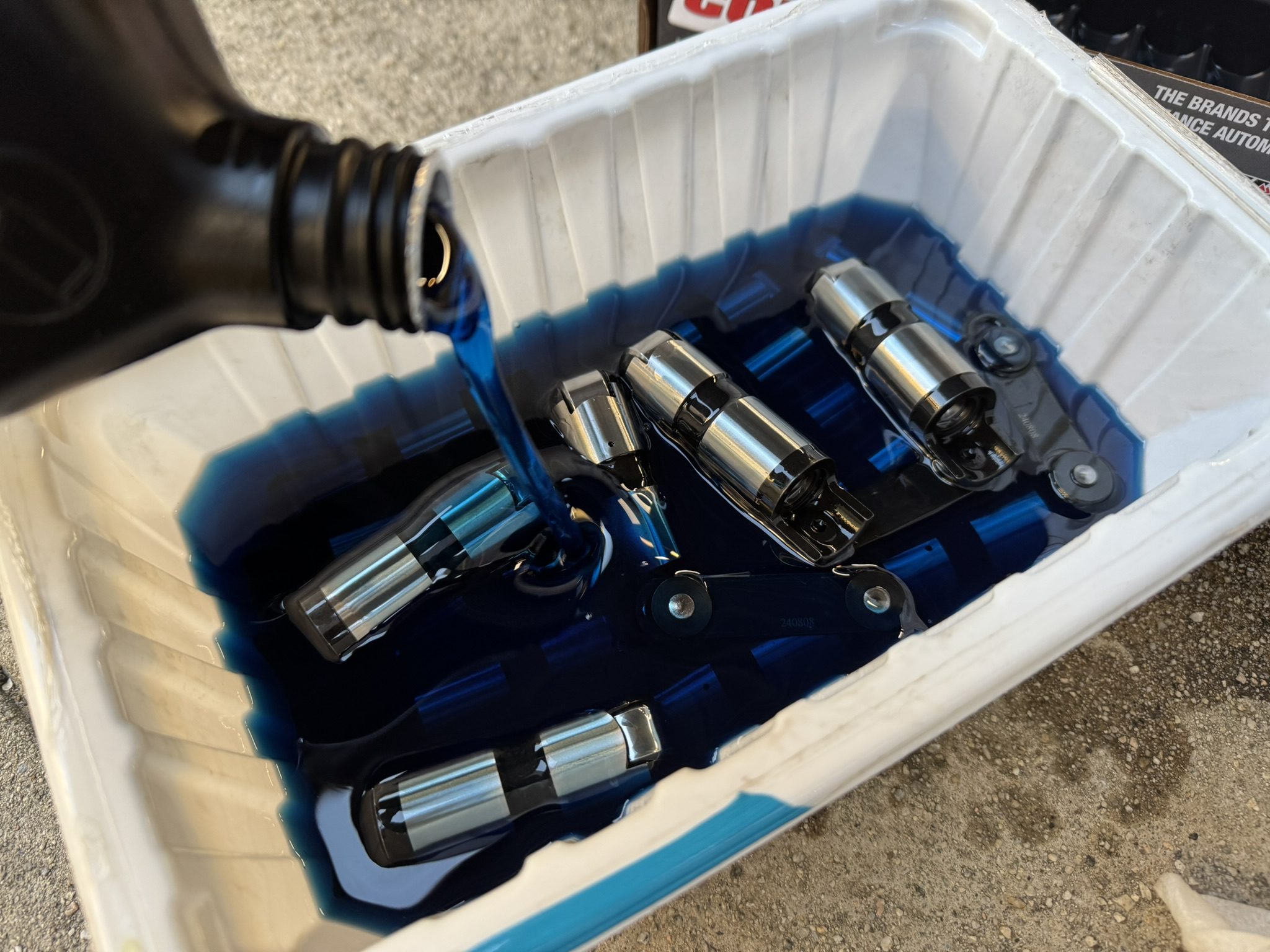
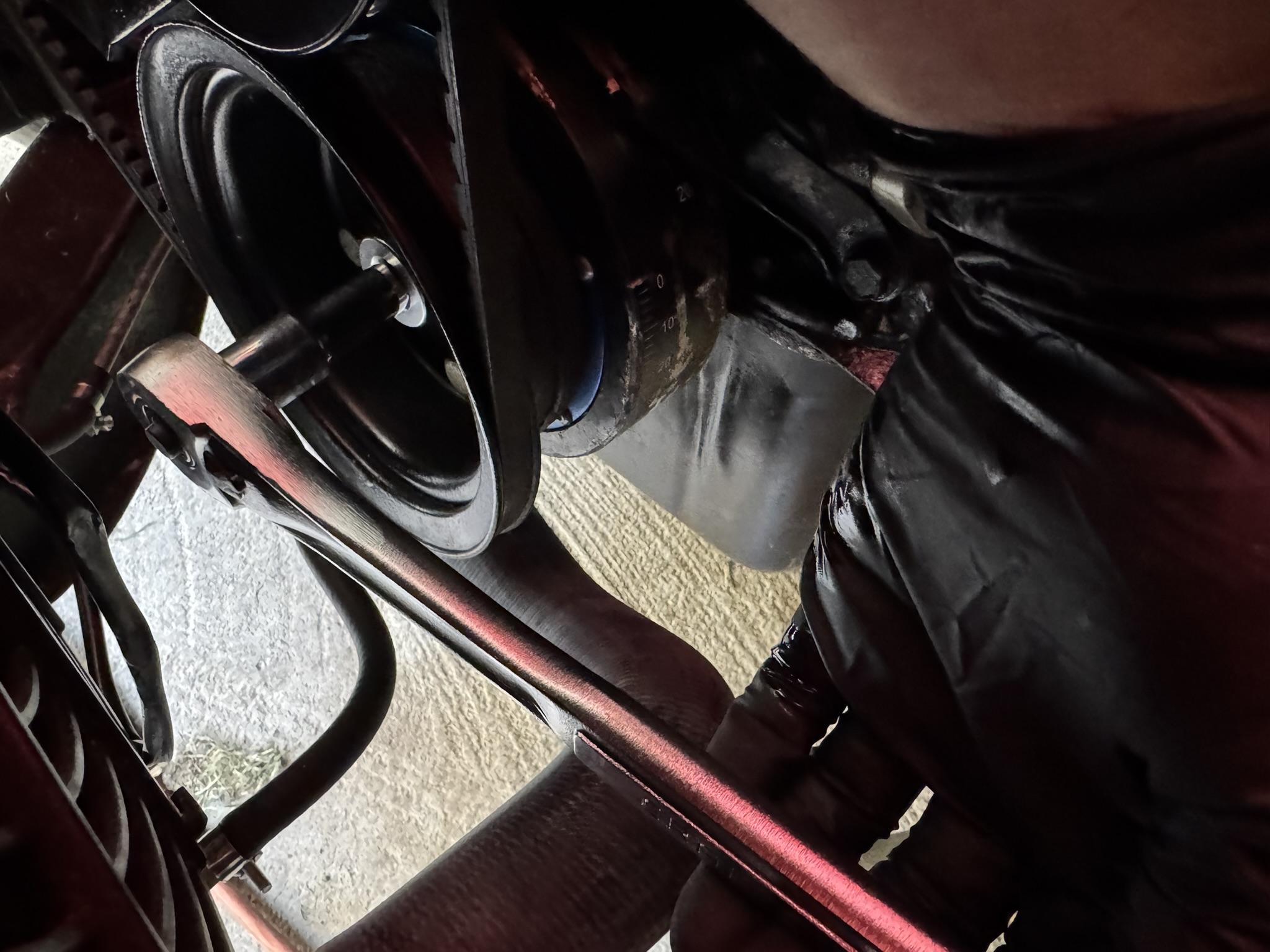
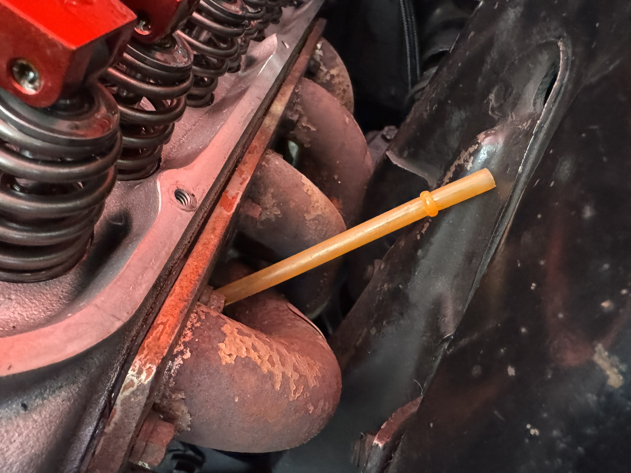
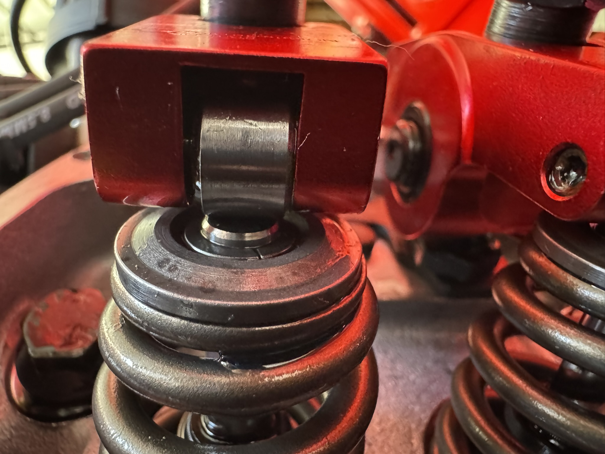
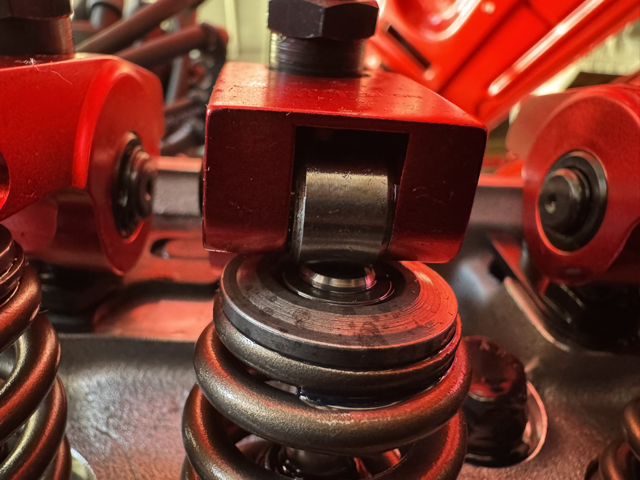
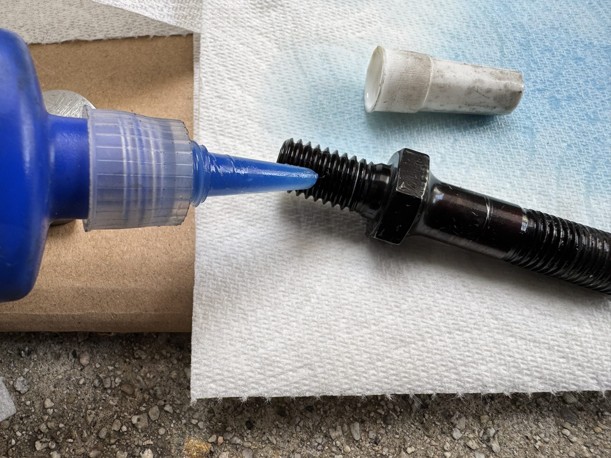
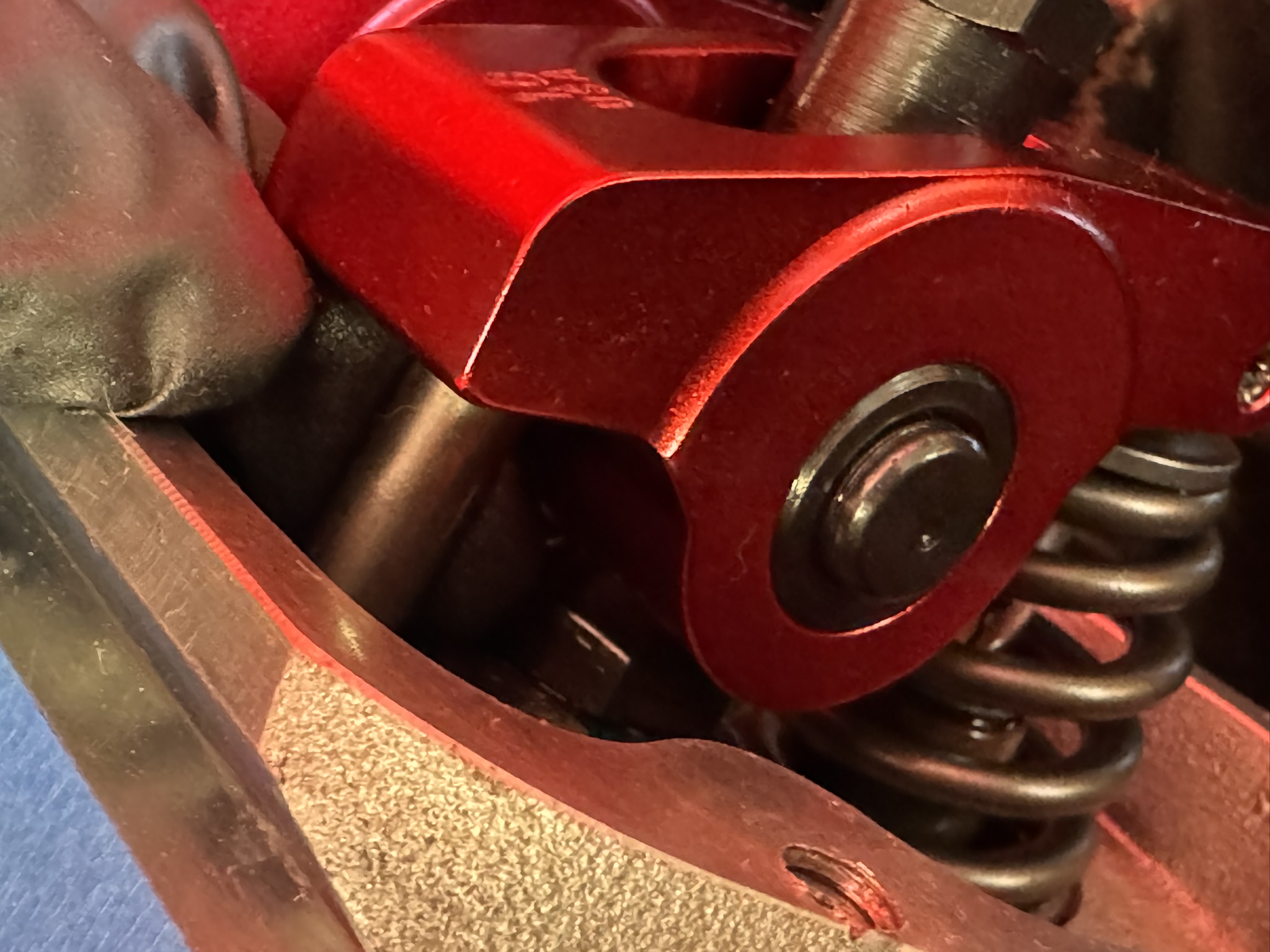
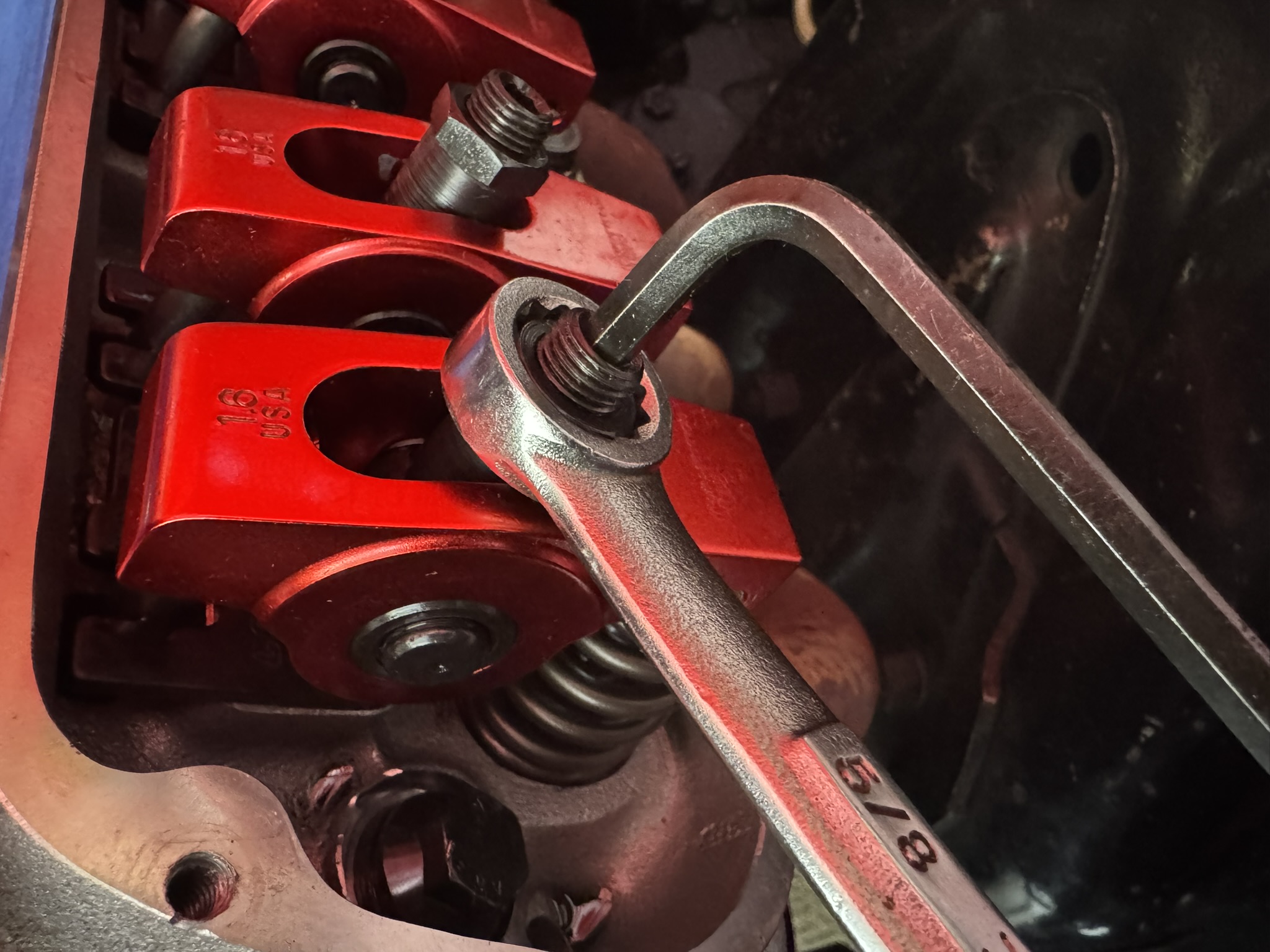
We’ve already pulled the valve covers and intake manifold because we were in the middle of another project. Adjustable guide plates can be installed by only removing the valve covers, removing the intake isn’t necessary. Our valvetrain is a mix of Edelbrock and COMP Cams components, all of which were either part of a kit or recommended. Let’s take a closer look at the issue. (Image/Christopher Campbell)Here’s a close-up of the rocker arms on cylinder #1 of our 351W. Note how both rocker arms are angled slightly inward? Let’s get a closer look directly at the contact point. (Image/Christopher Campbell)This straight-on shot shows how far the intake rocker is shifted to the left. The uneven loading will accelerate wear on the bearings and could potentially cause a failure down the road that would send needle bearings through the engine. It’s well worth addressing, in our opinion. (Image/Christopher Campbell)As part of our valvetrain teardown, we’re also going to be swapping in a new set of roller lifters since we discovered a newly sheared link bar (left). It appears to have just happened when we last cranked the engine to turn the car around. We don’t know why the bars are facing towards the cylinders instead of the more typical orientation facing the valley. (Image/Christopher Campbell)The link bar and both buttons were just laying behind the lifters, none of which showed any damage, so it looks like our timing for this project was serendipitous. (Image/Christopher Campbell)We called up Edelbrock for a replacement recommendation and they suggested the new COMP Cams Evolution Hydraulic Roller Lifters featuring their new Hydraulic Cartridge Technology (HCT). (Image/Christopher Campbell)HCT refers to COMP’s fully rebuildable, self-contained hydraulic cartridge within a thick-walled lifter body. These highly efficient cartridges require less oil volume, meaning they are responsive and quiet at start up and less affected by oil aeration. Their precision-controlled bleed down rate also ensures excellent performance at higher RPM. (Image/Christopher Campbell)After gently washing each lifter off in mineral spirits to remove any small debris, we left them to bath in break-in engine oil overnight before getting started on the pushrod guide plates. (Image/Christopher Campbell)To begin our swap, we need to rotate the engine until we’re at top dead center (TDC) on the compression stroke for the cylinder that we’re working on. We recommend pulling your spark plugs or you’re in for an arm workout. (Image/Christopher Campbell)Pick your favorite way to determine TDC, we’re fans of the plastic straw in the spark plug hole. We don’t need absolute precision here, just close. (Image/Christopher Campbell)We’re looking for TDC on the compression stroke because both rockers will be on the base circle of the cam and fully closed. This means there will be no upward pressure on the rockers from the pushrods. Both rockers should be sitting even like this. (Image/Christopher Campbell)To remove the poly locks, you’ll need an Allen wrench and a box end wrench. Once you break the Allen key loose, the poly lock will spin out by hand. (Image/Christopher Campbell)With the rockers out of the way, we can get a look at our single piece pushrod guide plate. This style of plate usually offers enough adjustment for most combinations, but as you can see, we have no wiggle room to align our rockers more precisely. The rocker arm studs will need to be removed to swap them. (Image/Christopher Campbell)The simple answer from COMP Cams is these two-piece adjustable guides that fit both small block Ford and small block Chevy engine with 5/16″ pushrods. These interlocking plates allow for much more precise location of rocker arms. (Image/Christopher Campbell)It doesn’t really matter in the end, but spacing the two plates at roughly the same overall width as the single piece plate that removed is a great starting point. The main thing to watch here is the clearance from the pushrod to the head. The rocker arm studs should be just finger tight at this point. (Image/Christopher Campbell)Already looking better with just a rough guesstimate! The adjusting nut on the rocker arm should be just tight enough to remove any up and down movement in the pushrod. (Image/Christopher Campbell)From here, it’s all about the fine tuning the gap between the two-piece guide plates. We used a flathead screwdriver with the tip wrapped in electrical tap to twist and slowly adjust the gap until we liked the position of the contact point on the valve stem. (Image/Christopher Campbell)Here’s the intake valve for the same cylinder. If you’re doing this in the car, a smartphone with a good camera will be worth its weight in gold for helping you see the contact point up close. (Image/Christopher Campbell)Here’s where we get controversial. Once you’re satisfied with the position of the plates, many people swear that you need to tack weld them together to prevent movement. Per Edelbrock and COMP Cams this is an optional step, not a necessary one. As long as the plates don’t move while you’re torquing the rocker arm stud, they’re not going to move at all afterwards. We’re leaving ours unwelded. (Image/Christopher Campbell)If you’re running Edelbrock aluminum heads like us, Edelbrock calls for blue Loctite on the rocker arm studs. They should be torqued to 45 lb.-ft. (Image/Christopher Campbell)We’re ready to reassemble the valvetrain on this cylinder, so we dabbed some assembly lube on both ends of the pushrods for good measure. We’re not ready to lock things down yet, though. (Image/Christopher Campbell)You could set the preload on the lifters at this point, but we prefer the I.C.E and E.O.I. methods. This image shows the intake and exhaust valve locations for a small block Ford with 351W and 5.0 HO firing order (Image/Christopher Campbell)I.C.E stands for “Intake Closing, set Exhaust.” This means that to set the preload on the exhaust valve, we need to rotate the engine over until the intake valve is fully open and just begins to close. Holding your hand on the intake rocker arm will help you feel the change in movement direction. At this point the exhaust valve lifter will be sitting on the base circle of the cam and will be fully closed. (Image/Christopher Campbell)By lightly turning the exhaust valve pushrod with your fingers as you tighten the adjusting nut, you will feel a point at which there will be slight change in the resistance to the turning. At this point, you have taken all the excess slack out of the pushrod. You are now at zero lash. (Image/Christopher Campbell)We should also note that you can do that by reaching underneath the rocker if your intake manifold is still in place, though it may be challenging depending on how chunky your rocker arms are. (Image/Christopher Campbell)The next step is to rotate the engine until the exhaust valve is fully closed and the intake valve just begins to open. The is the E.O.I step, or “Exhaust Opening, set Intake.” Now the intake valve lifter will be sitting on the base circle of the cam and fully closed. The adjusting process with the pushrod is the same as the exhaust valve. (Image/Christopher Campbell)The Evolution Hydraulic Roller Lifters have nominally 0.125” of internal travel within the hydraulic cartridge. For most engines with adjustable rockers, 3/4 to one full turn of the adjusting nut past zero lash is adequate to set lifter preload. (Image/Christopher Campbell)Once you’ve set your preload, it’s time to lock the rocker into place. Run your Allen key through the box end of your wrench and then then then together. They should move roughly 1/8 of a turn and firmly lock. (Image/Christopher Campbell)That’s one cylinder done! To complete the guide plate swap, you can follow the firing order of the engine or just go bank by bank. A great way to check yourself is to look down the row of rockers. The Allen key locks should all be roughly the same height. If one is sticking up more than a half thread or so, go back and check that valve. (Image/Christopher Campbell)
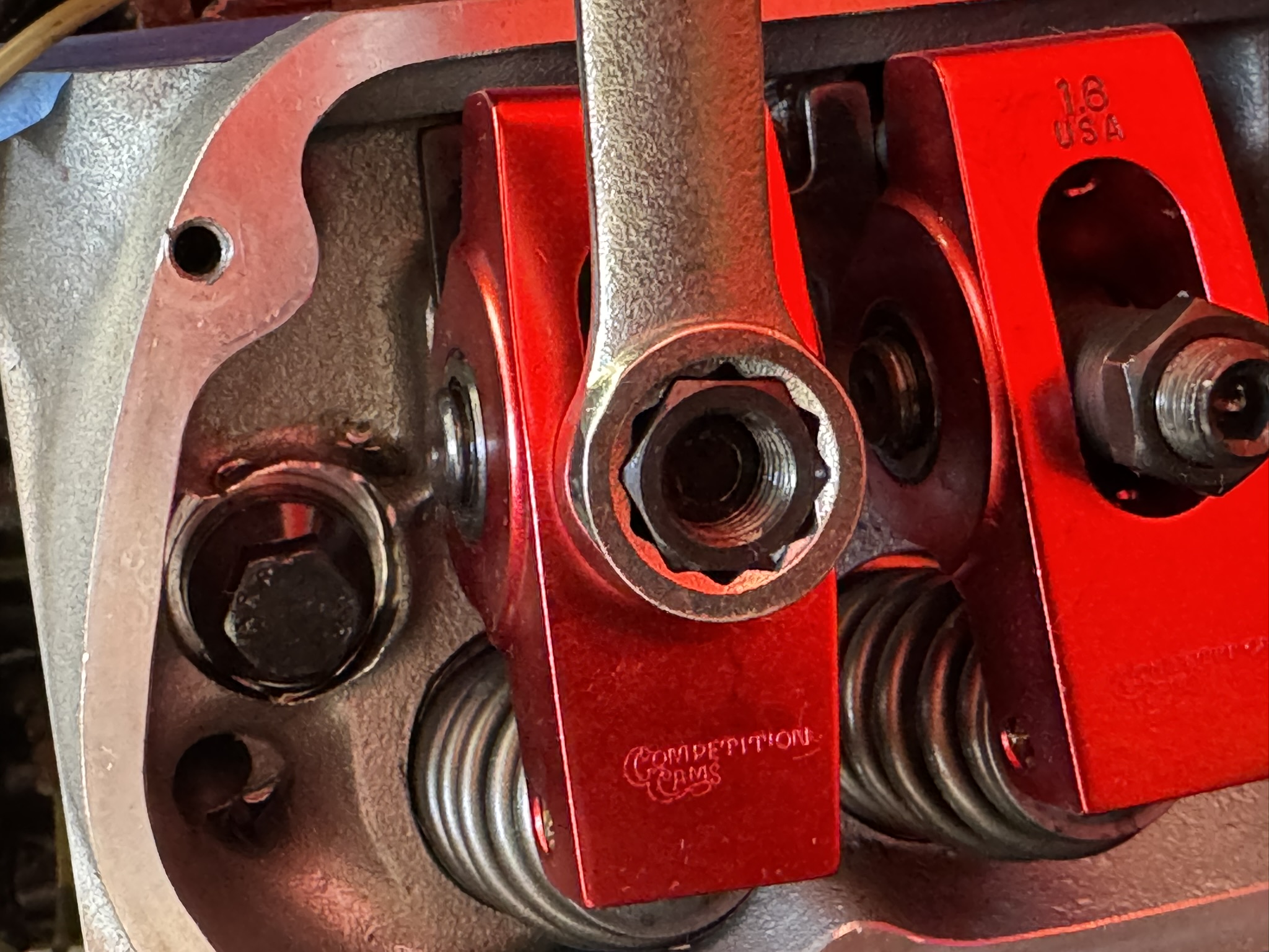
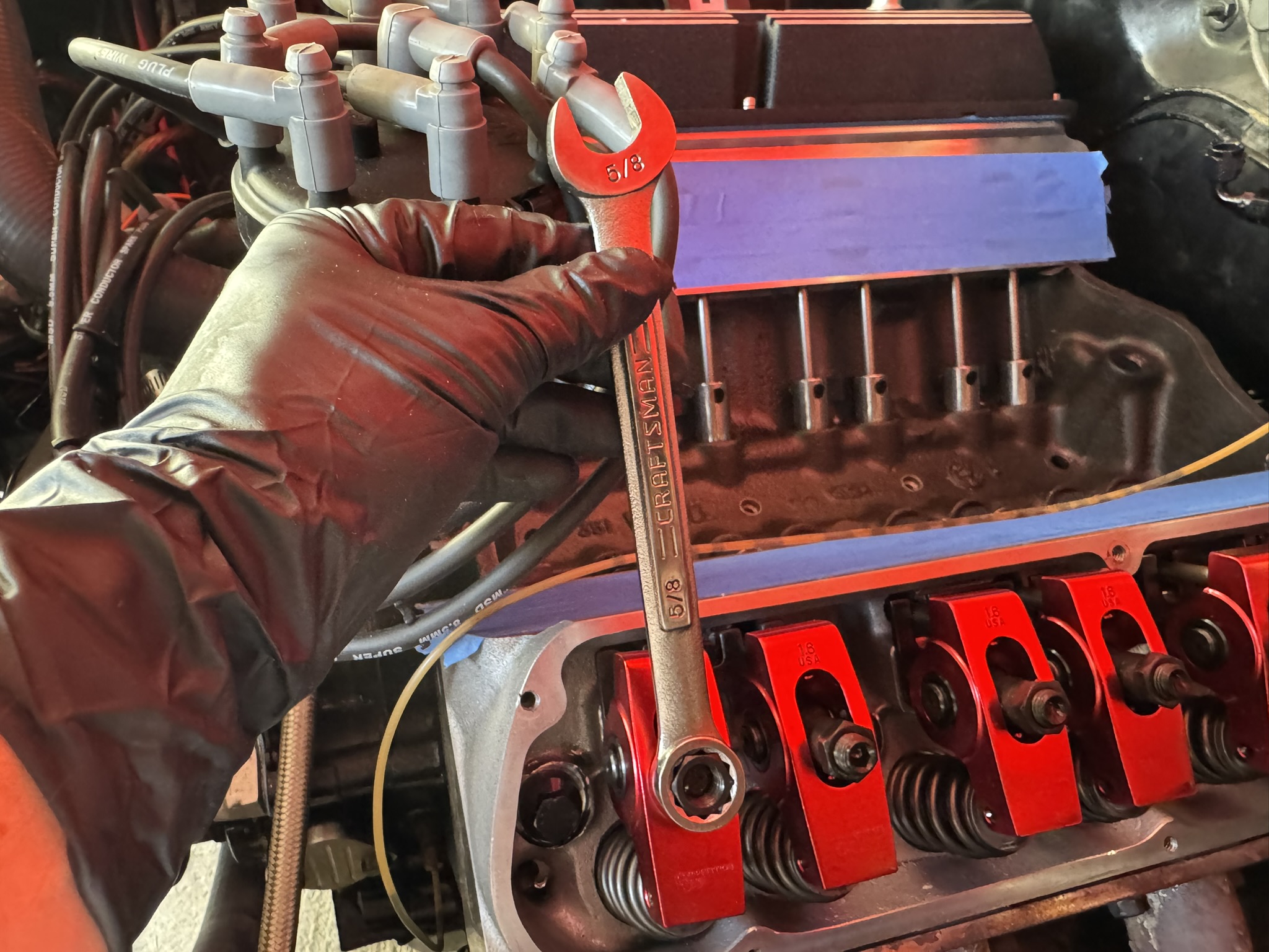
Christopher Campbell has been heavily involved in the automotive world since he began building his first car, a 1967 Ford Ranchero, with his dad at the age of 14. That started a lifelong passion with custom hot rods and muscle cars. After graduating from Cal State Long Beach, he went to work for HOT ROD magazine as Associate Editor. From there he became Technical Editor at Popular Hot Rodding magazine. Currently he creates freelance content for OnAllCylinders as well as many diverse enthusiast magazine titles such as HOT ROD, Muscle Mustangs and Fast Fords, Mopar Muscle, Super Chevy, Mustang Monthly, and 8-Lug.
Comments
One response to “How to Install COMP Cams Adjustable Pushrod Guide Plates for SBF & SBC”
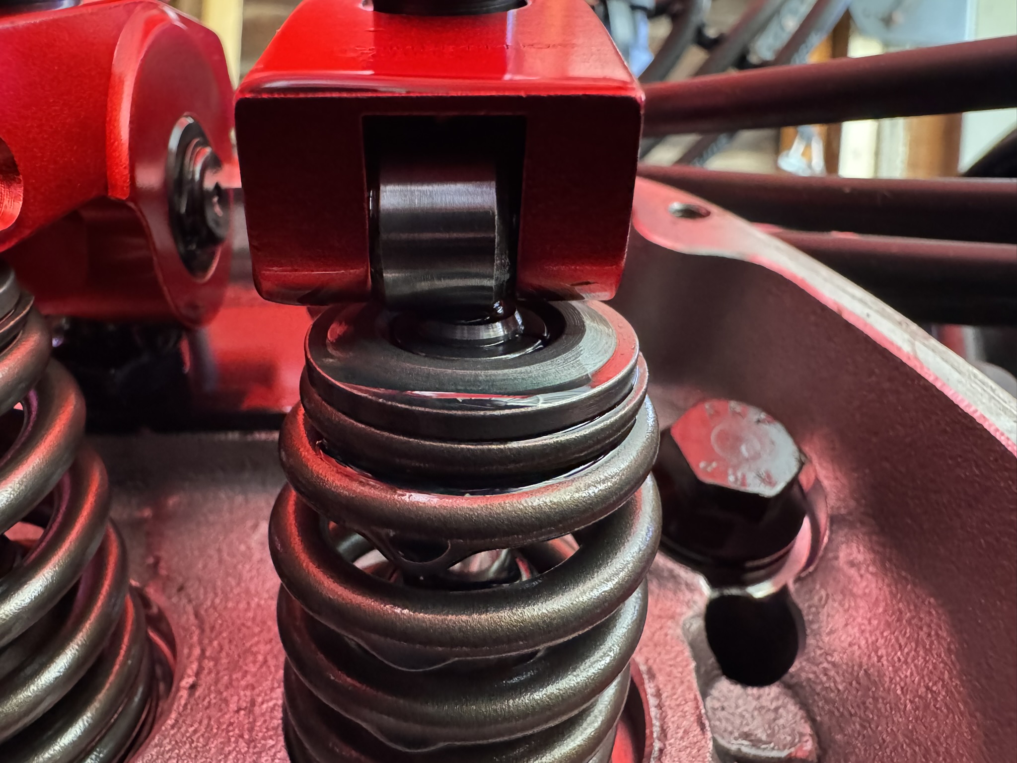
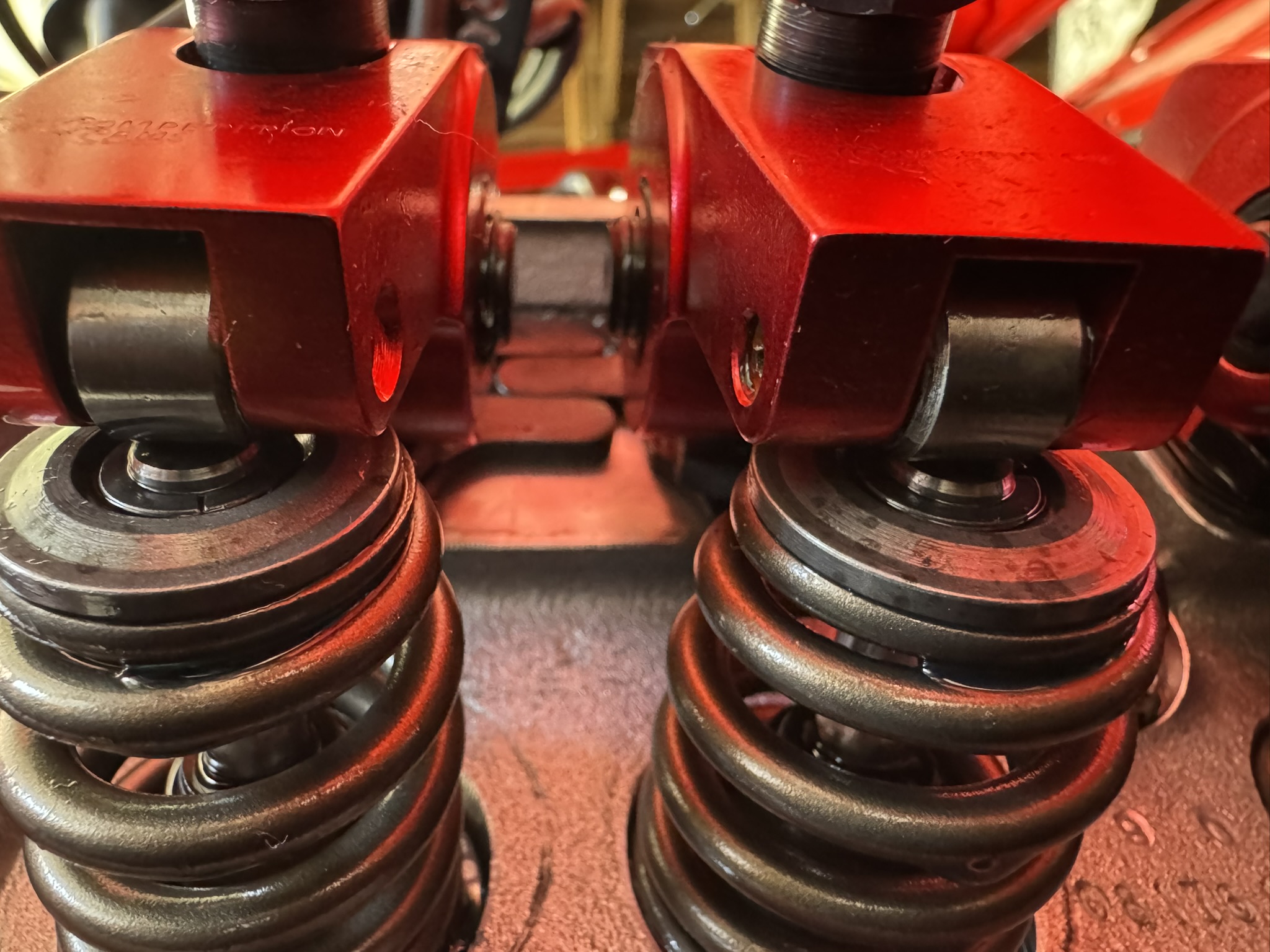
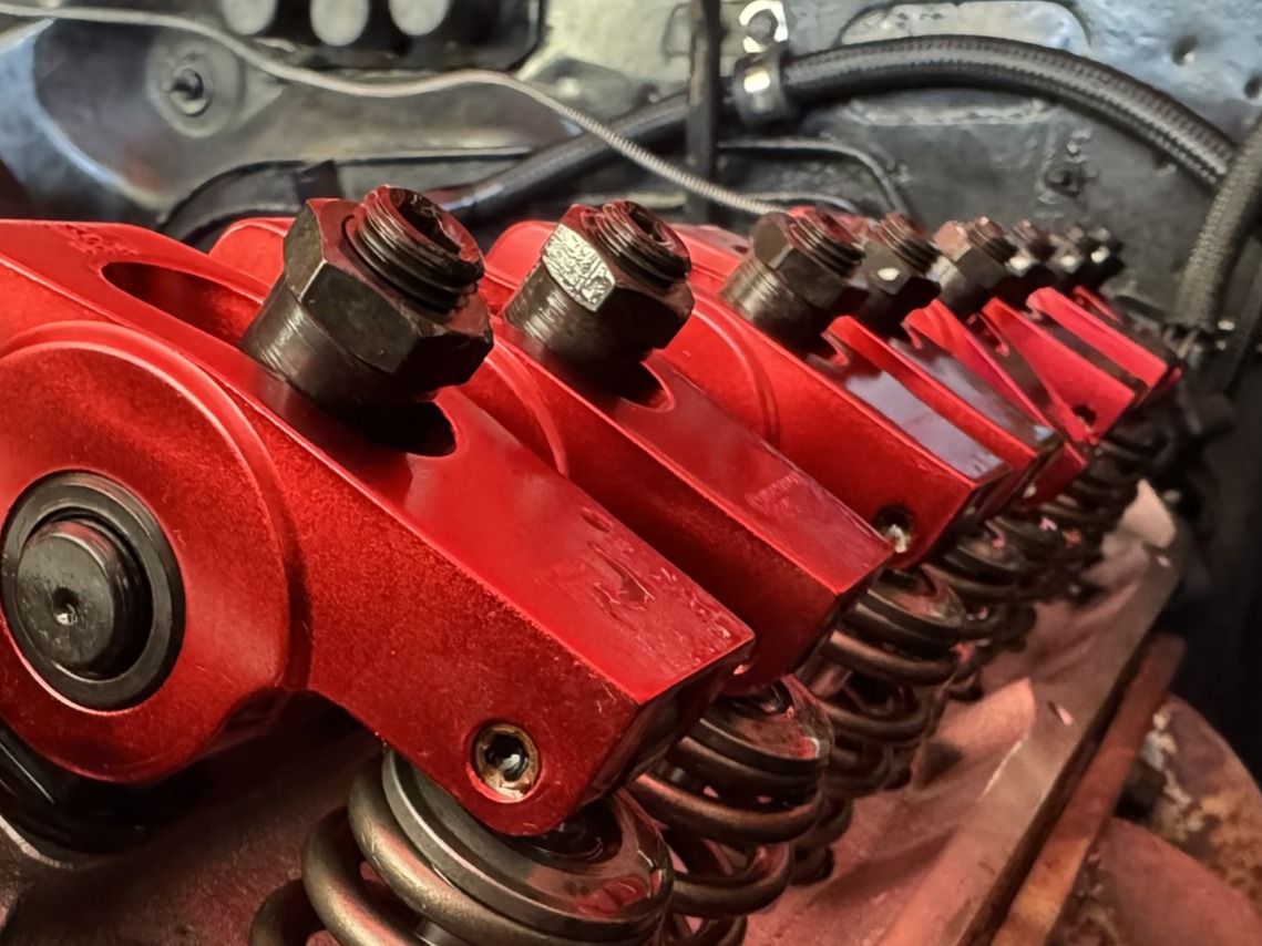
I’d be almost as concerned about what looks like .100″ or more of slop between those springs and the locators. Yikes.