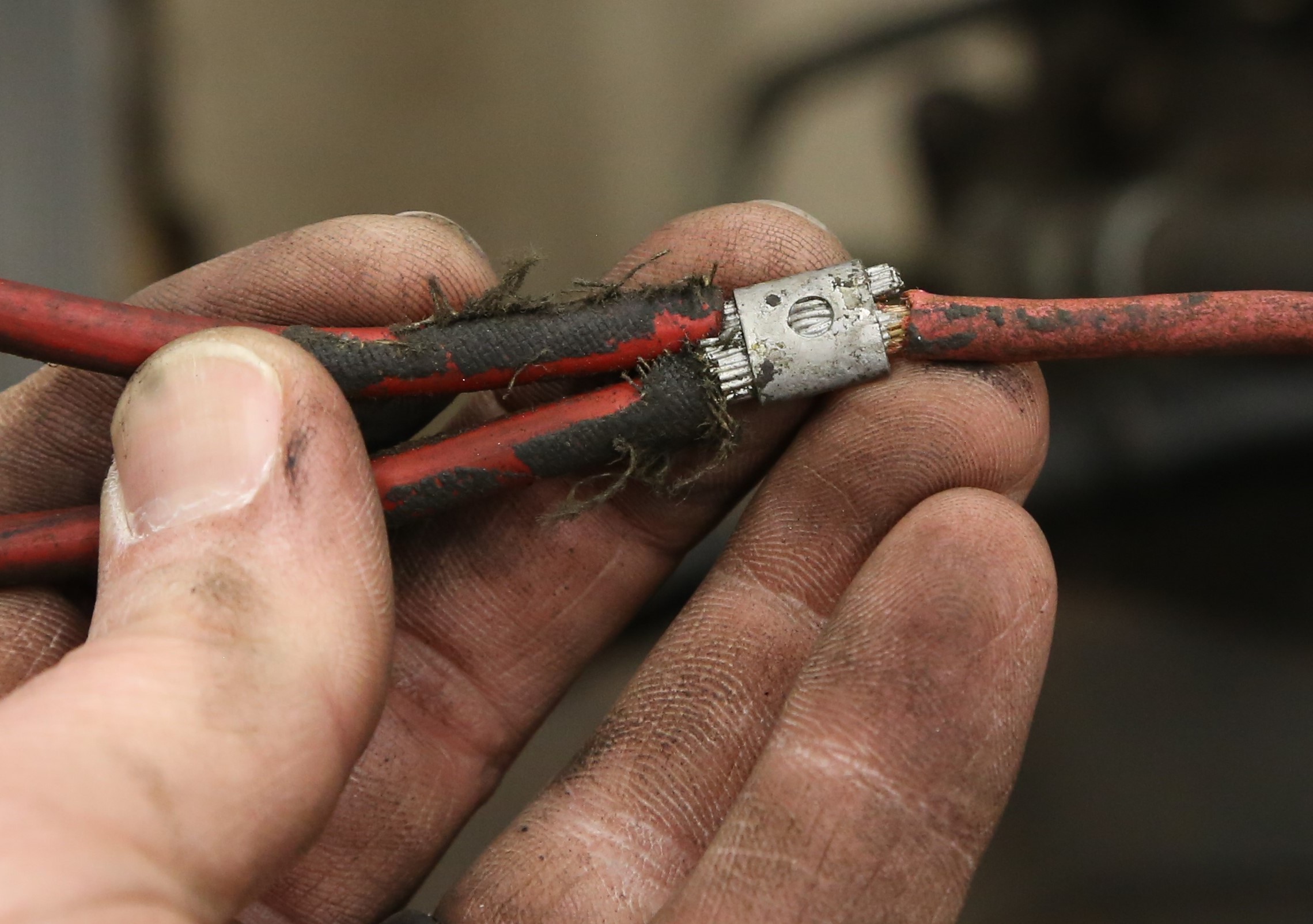
When you buy a classic car or unfinished project, you are bound to find some wiring issues. It’s inevitable, like taxes and grease on your T-shirt. A wiring harness tends to age quite poorly compared to other systems. Wires get brittle and crack, connectors corrode, and relays stop, er, relaying. Even worse, wiring harnesses are far too often subject to hacks and modifications that virtually guarantee electrical gremlins.
One option is to rip out your vehicle’s wiring harness and replace it with a brand new one from manufacturers like Painless Performance, Ron Francis Wiring, and American Auto Wire. But if the basic harness is sound and you just need to replace some wires, re-do connections, or want to add an additional circuit, there are ways to do it properly. Let’s take a look at some of them.
Soldered Connections
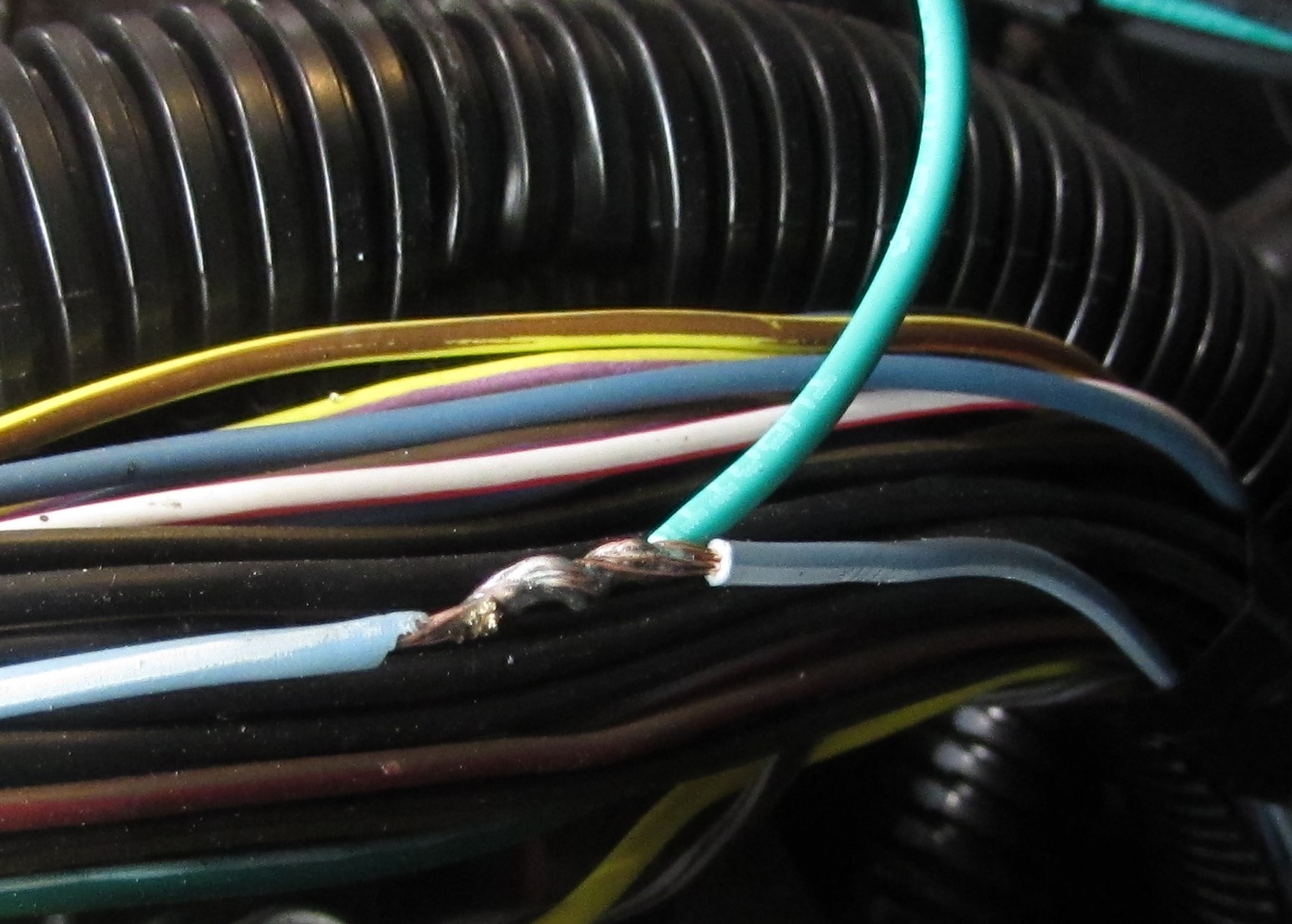
Soldering used to be the go-to method for repairing wire connections. The wiring industry has changed its tune over the last 10 or 15 years, and now emphasizes crimping connections instead. When done correctly, a soldered wire joint will last for years. But it takes practice and patience to learn how to do it properly.
The main issue with soldered joints is vibration. Soldering eliminates the flexibility of the joint. Cars vibrate a lot, and over time that vibration can fatigue and eventually break a soldered connection. Soldering tends to increase the resistance of a joint, which is no good for modern electronics that operate on pulse wave modulation (PWM) and low-voltage, resistance-based input/outputs.
The last issue is moisture. Soldering pushes a lot of heat into the wire, making it vulnerable to moisture. Once moisture gets inside a soldered joint, corrosion follows. Small wonder NASA and the FAA no longer allow soldering on spacecraft and aircraft electrical systems. Most OEM vehicle manufacturers don’t allow dealership techs to use solder, either.
How To Solder Properly
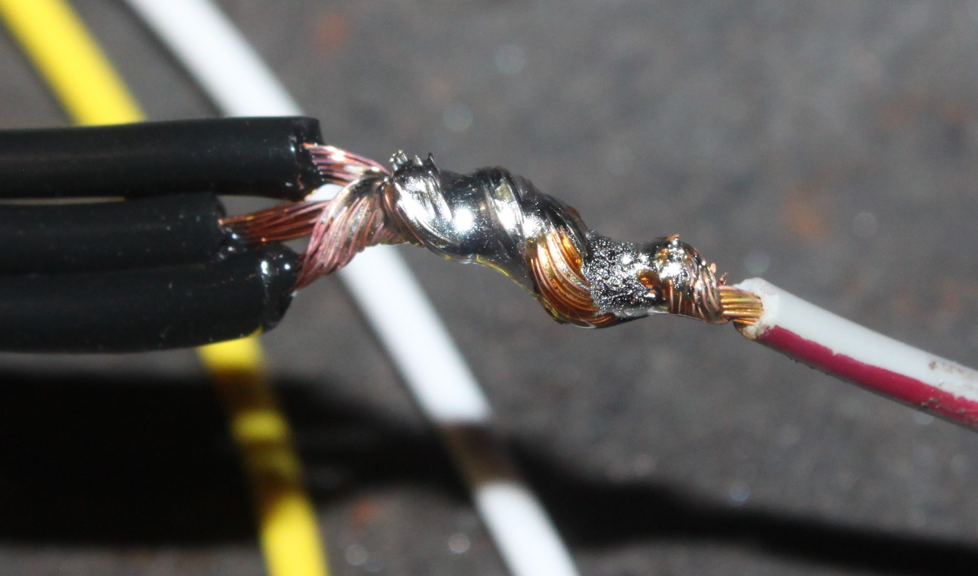
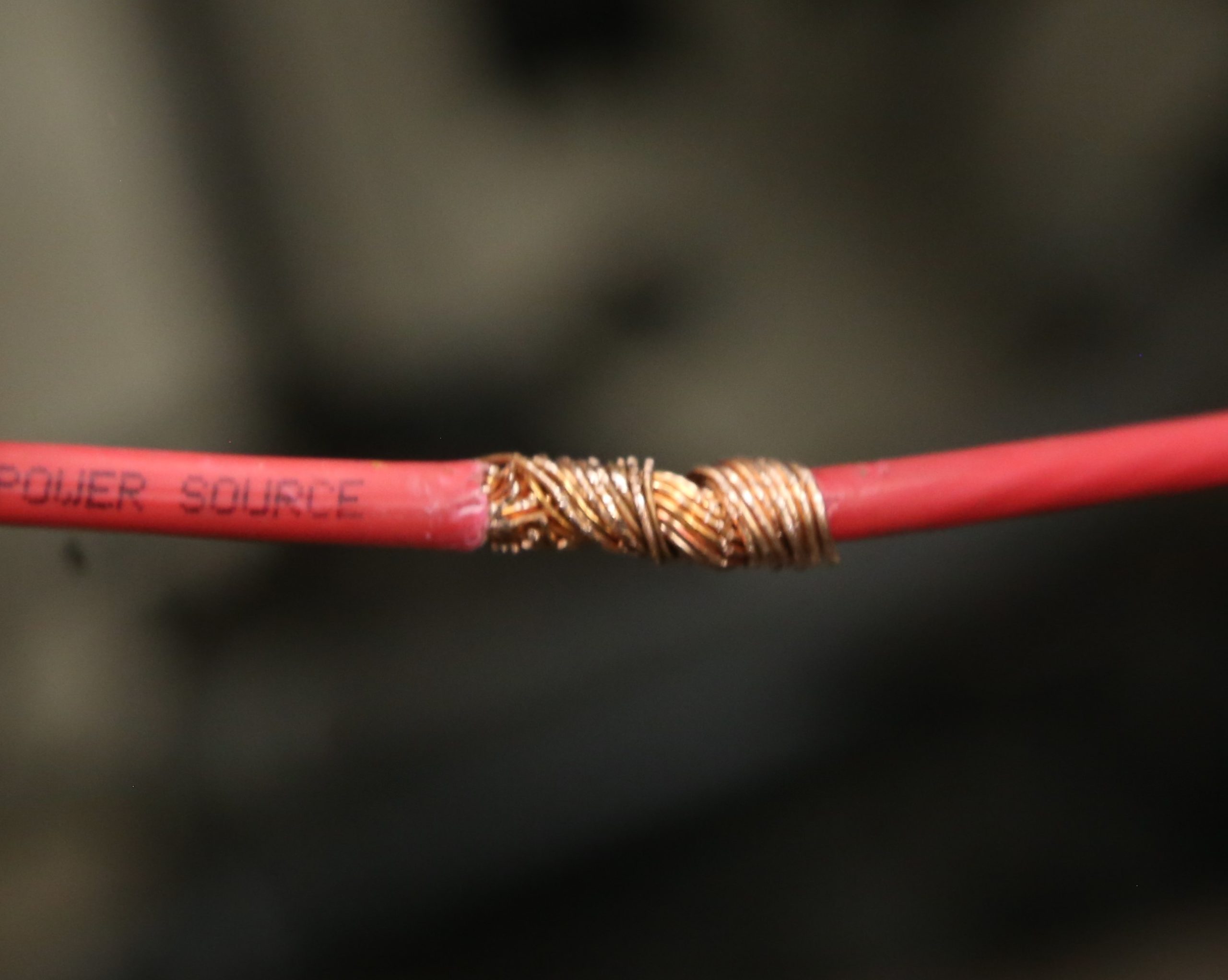
The biggest problem with soldering is heat. Solder must flow through a joint in order to make a solid connection. If you can’t see the strands of wire through the solder, then you likely have a ‘cold’ solder joint, which is not very strong and will increase the resistance of the circuit dramatically.
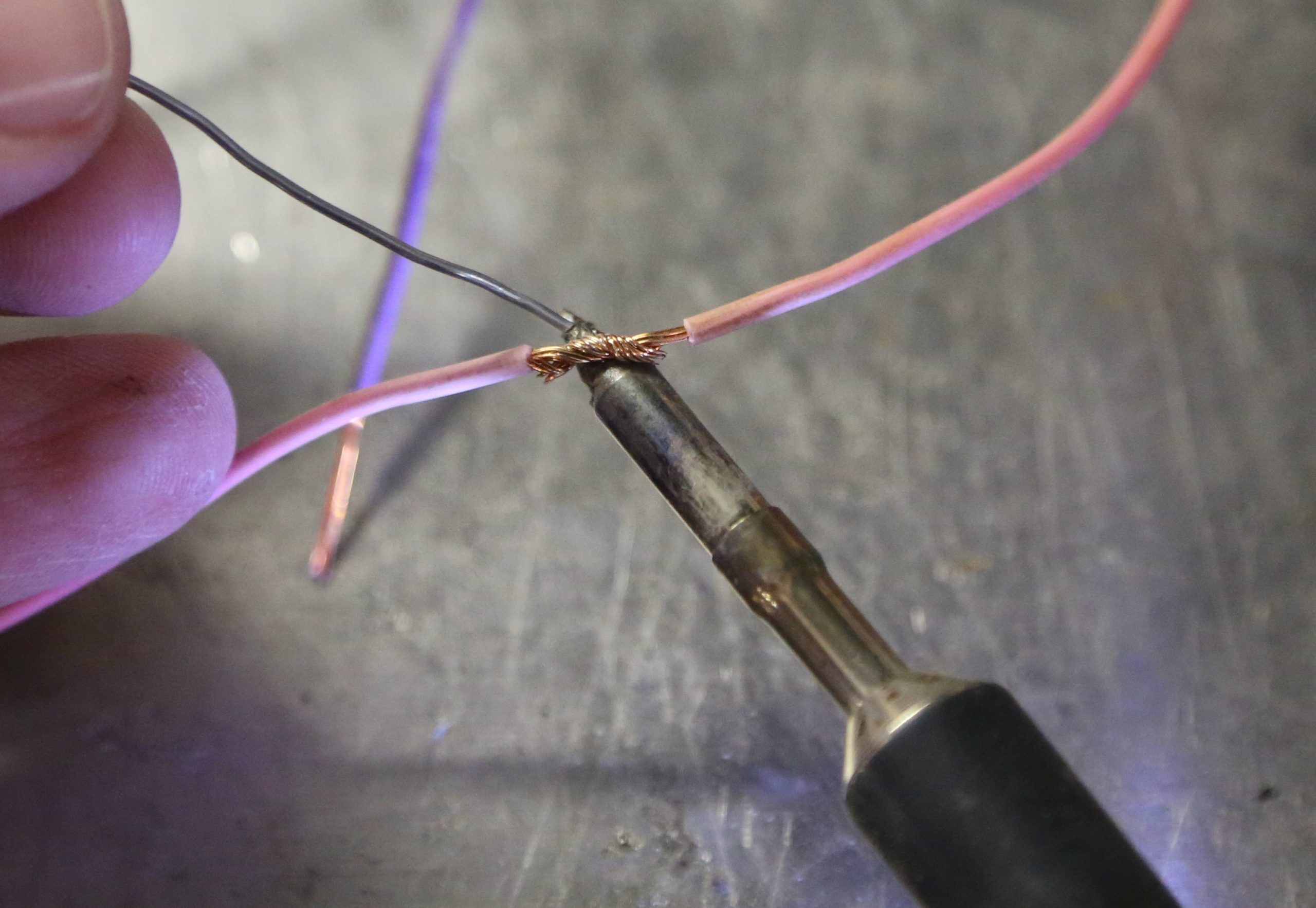
This is why you need a good quality soldering iron, preferably with an adjustable temperature control. The soldering iron must be fully heated before attempting to solder wire. Electrical solder (60/40 Sn/Pb) melts at 370 degrees F. If the temperature is set too low, it will take a very long time to get the wire hot enough to accept the solder once it melts. 750 degrees F is a good temperature for soldering. You want the wire to get hot as fast as possible so the heat is contained at the junction instead of soaking through the rest of the wire run. Heat travels fast in copper. When you find a soldered wire that is stiff an inch or two away from the actual joint, you know it was heated too long.
The best method for soldering is to lay the wire on the tip of the soldering iron once it has reached full temperature, Add the solder to the leading edge of the tip and joint so the pen heats the solder, and the wire pulls the solder through the wires. You want the wire strands to be coated with solder with no large blobs. Soldering 12 gauge and larger wire requires more heat and time. Crimping is a much better method for connecting large gauge wire.
If you are connecting a wire to a terminal connector, never heat the terminal, fill it with solder, and then insert a cold wire. The joint will hold, but it’s nothing more than a giant cold solder joint and will absolutely fail.
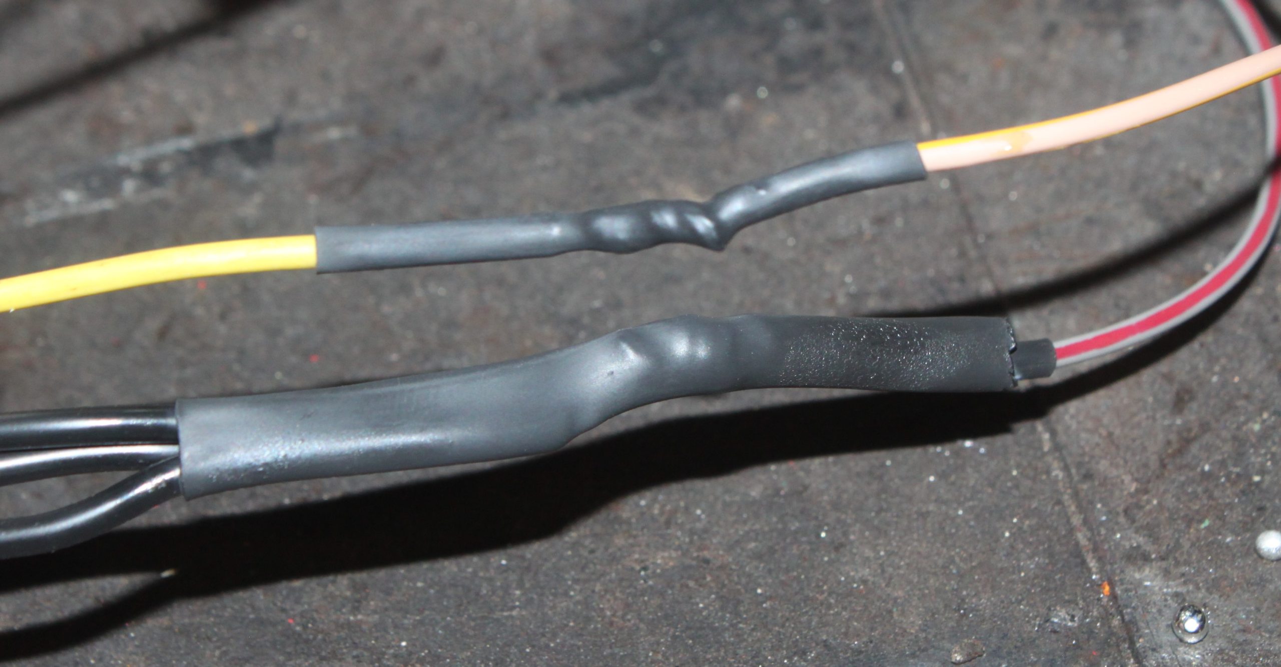
Once the you’ve soldered the joint, you have to protect it from the elements. Heat shrink is the best option, especially the type with sealing mastic or adhesive inside it. Good quality electrical tape such as 3M Super 33+ vinyl tape is next best.
Don’t use cheap tape to cover solder joints. The tape will peel off over time, leaving you with an exposed joint.
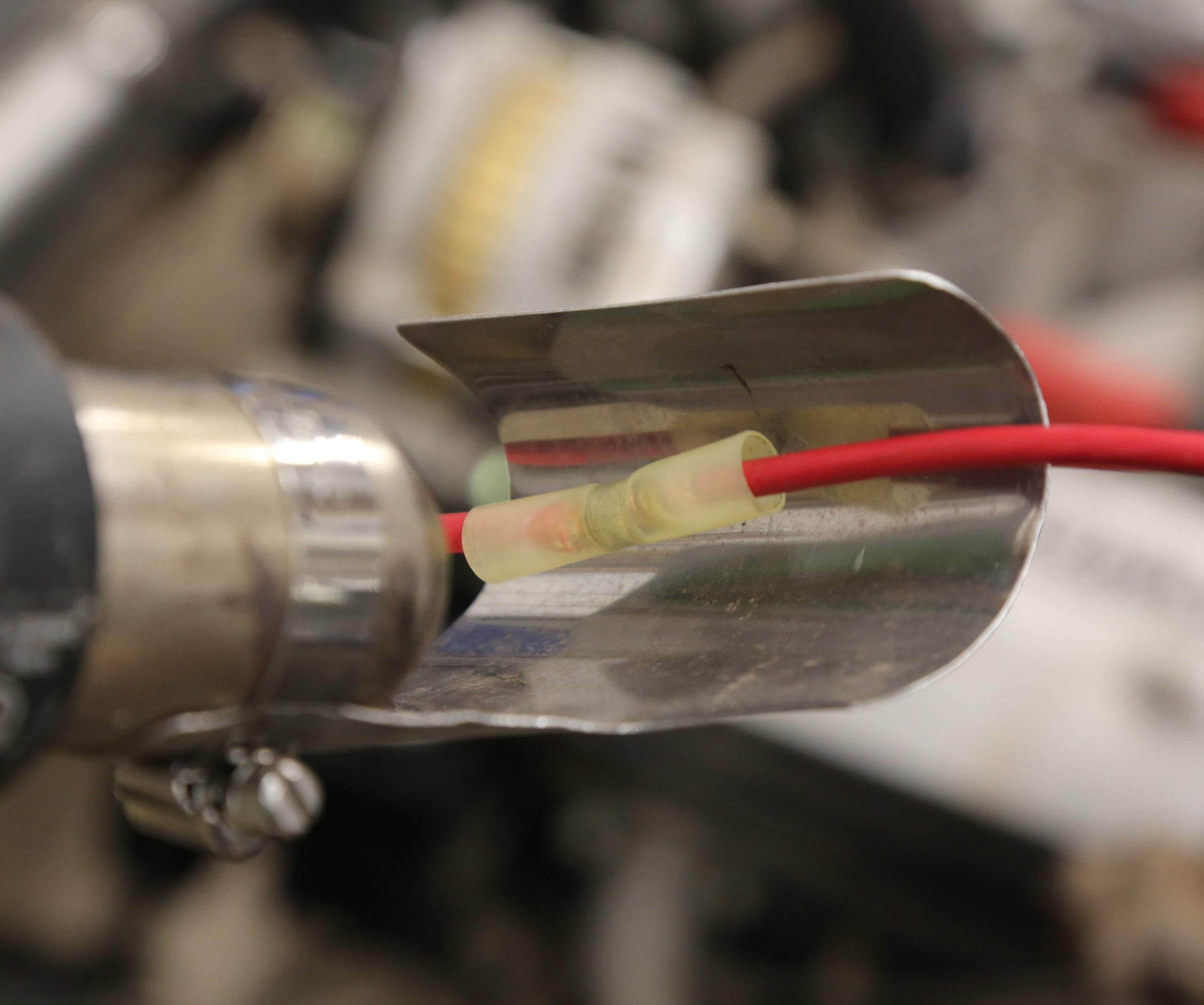
Self-Soldering Connectors
Self-soldering splice connectors are a good alternative to hand soldering. They look like butt splice crimp connectors, but instead of crimping them, you simply insert the wires and use a heat gun to melt the solder and heat shrink at once, leaving a clean, safe, and durable connection. A heat gun is the best way to seal these connecters; a lighter can burn the heat shrink.
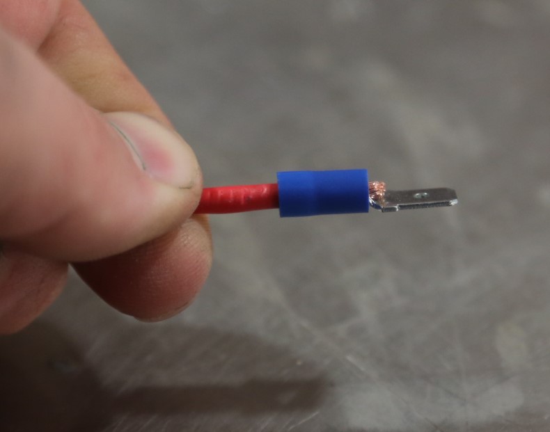
Crimping
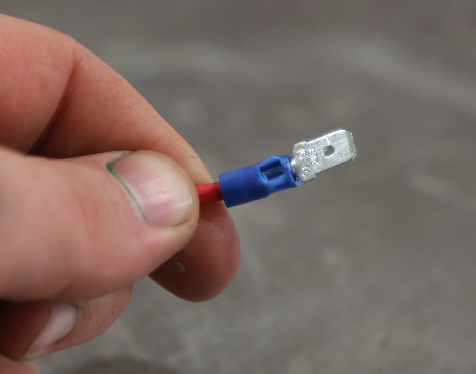
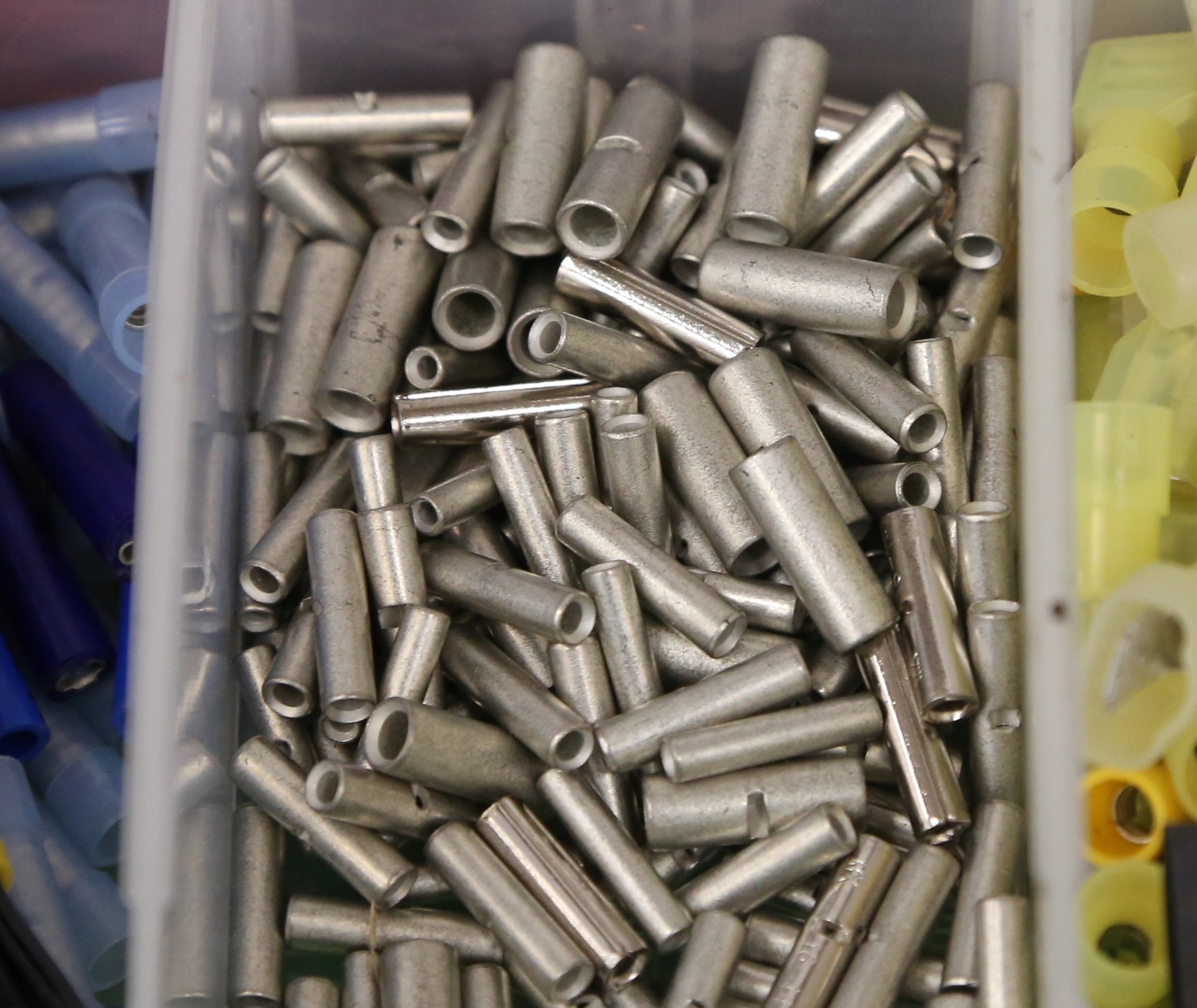
For most applications, crimp connections are more reliable than hand-soldered ones. A proper crimp doesn’t damage the wire, add heat, or limit flexibility. The most common crimp terminals are insulated, but uninsulated terminals are cleaner and can be made without being obvious. A properly made crimp will last longer than a soldered joint and is easier and faster to make.
Shopping for a good crimper? Read this buyer’s guide: Wire Crimpers 101
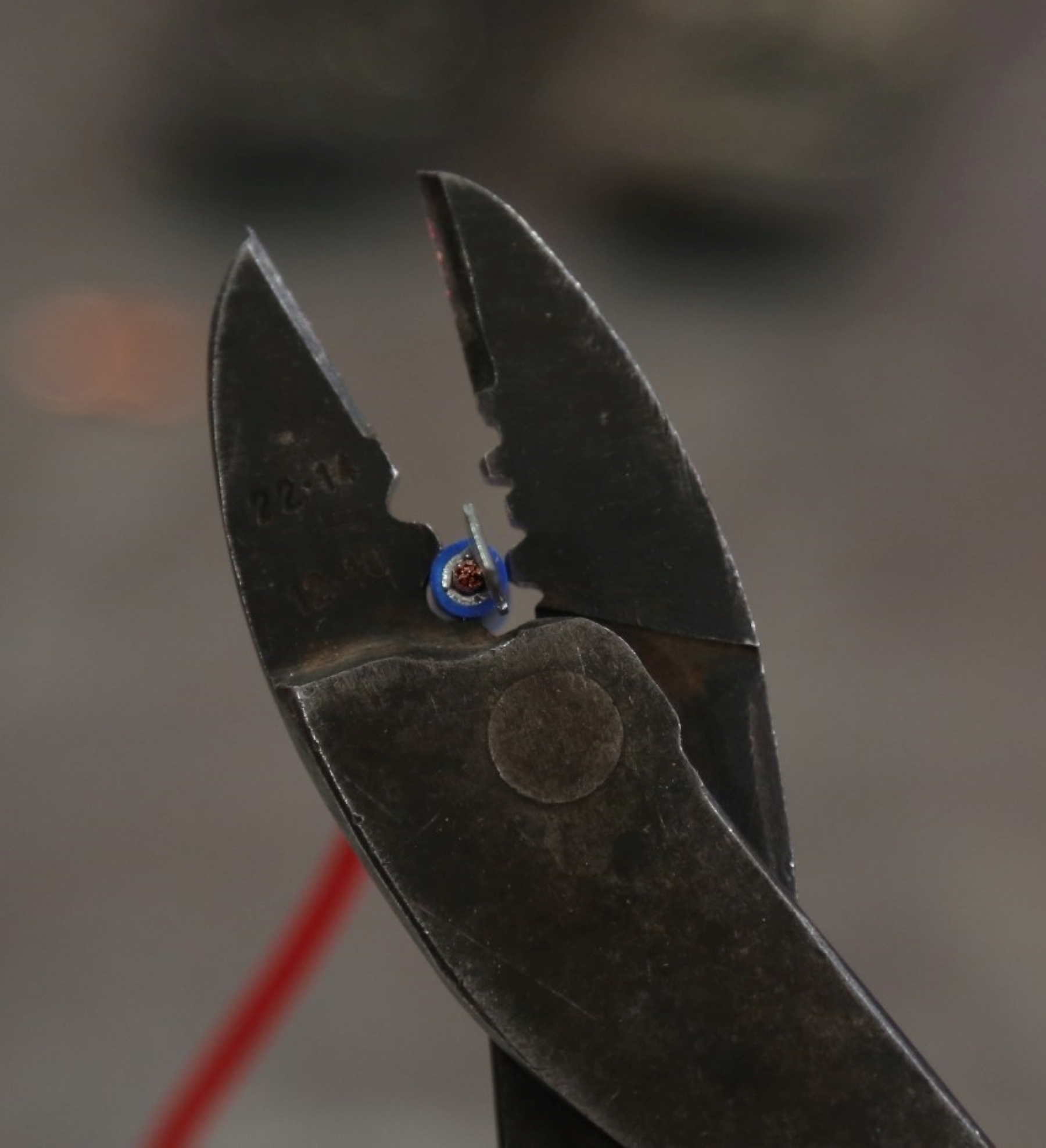
The key to a good crimp is using a tool compatible with the terminals you are using. Most common crimp tools have a non-insulated die (a half-moon and a tooth) and an insulated die (two shallow half-moons). In practice, the non-insulated die works well for both insulated and non-insulated terminals. When making a crimp with this die, the open end of the terminal (where the two halves of the crimp touch) is placed inside the half-moon and the tooth compresses the flat side. Insulated terminals do not require tape or heat shrink, but they look better when sealed. Non-insulated terminals require sealing just like soldered connections. Heat shrink is the best option.
For crimping really large wires (like battery cables) you need to use a specialty impact die tool. Jeff Smith gives you some insight on crimping battery terminals here.
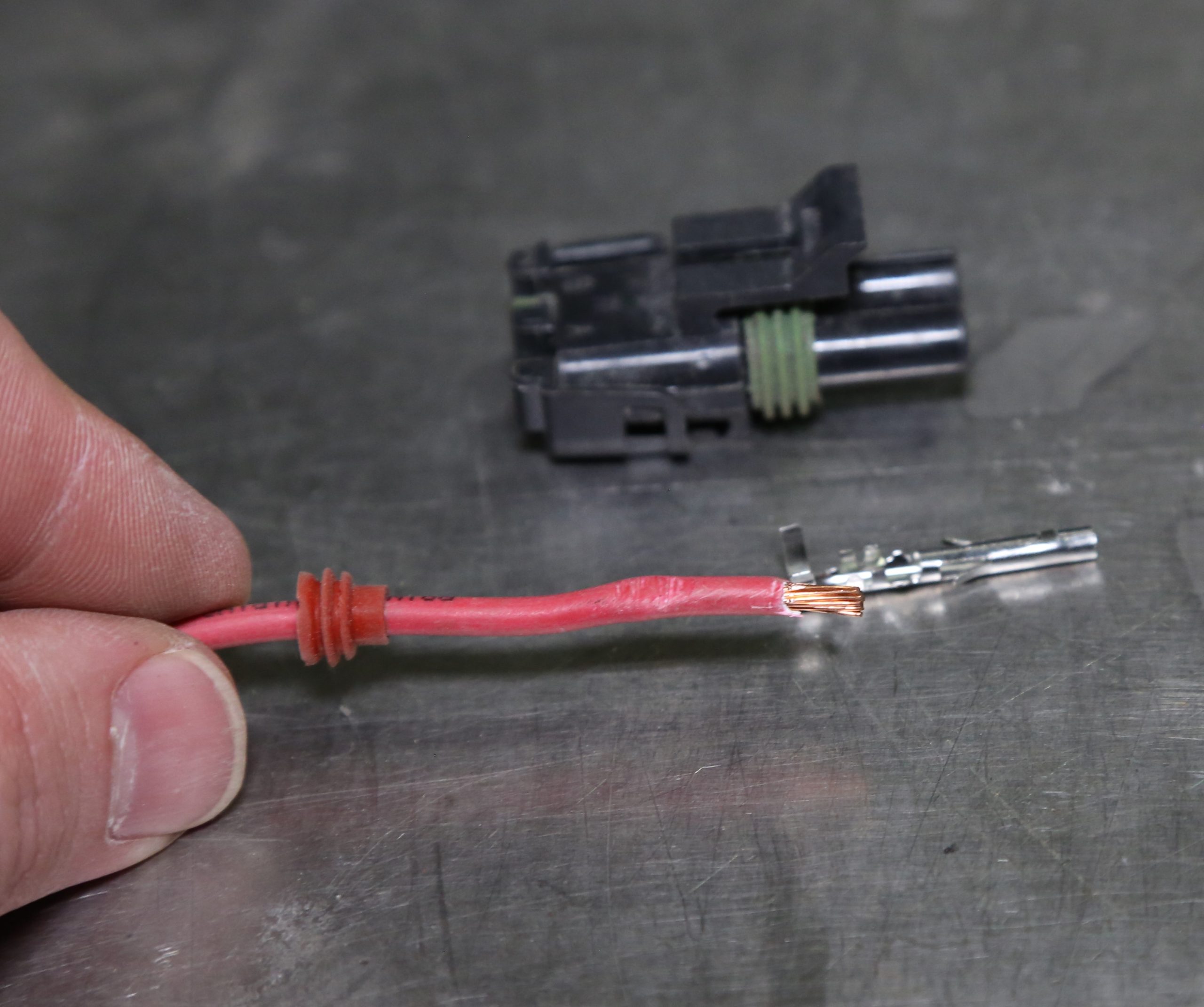
Specialty Terminals
Sometimes you just have to replace an entire wire for a component or circuit. Whether it was a burn, bad break, or a re-route, replacement requires removing the wire from the harness, removing the pin from the block or connector from both ends, and replacing it with new wire. Some connections use common ring or spade terminals. Others used a molded connector like the Packard 56, Deutsch, and GM’s Weather Pack and Metri-Pack.
Each type has its own terminals and require a dedicated crimper. (For example, read this article on how to properly assemble Deutsch connectors.) You can also get crimping tools with replaceable dies that can handle virtually any type of connector you may encounter. As a bonus, these tools typically have a ratcheting action with a release that ensures you don’t under- or over-crimp the terminal.
***
Repairing a wire harness can be tedious work. Take a breath, relax, and be patient. Once you have figured out how to make the repairs with good quality crimps or solder joints, you will be a pro in no time. For more helpful guidance, you may want to check out our podcast interview with Painless Performance, and get a closer look at some of the tools and techniques discussed in the article below.


Comments