In those prehistoric times prior to fuel injection, regulating fuel pressure on a hot carbureted car (race or otherwise) came to down to using one, two, or more deadhead regulators. Done deal, but those deadhead regulators came with their own issues.
For example, regulator creep—where the fuel pressure slowly creeps up—wasn’t uncommon. Deadhead regulators put an added load on the fuel pump too. Essentially, the fuel pump produces (for example) 15 pounds of pressure. The pump hammers the regulator check valve with those pressures and it has nowhere to go. This obviously increases the temperature of the fuel, sometimes to the point of vapor lock.
So basically, what you’re faced with is the potential for inconsistent fuel pressure numbers, added fuel heat, and the potential for engine flooding. It also tends to shorten the life of both the fuel pump and the regulator(s).
Bottom line here is a deadhead regulator is nothing more than an adjustable restriction in the fuel line, although they still have their place in some applications.
Meet the Bypass Fuel Regulator
Then poof! Fuel injection became popular and with it, bypass regulators became common.
Here, the regulator takes in all of the fuel the pump produced, regulates it to the required pressure, and returns the un-needed fuel to the gas tank. For a street car application, this makes for a much more reliable, consistent setup. It keeps the fuel cool, it eliminates pressure creep, and it increases the life of the fuel pump and the regulator.
So far so good. It’s easy to see how positive the benefits are for fuel injected applications, but they also apply directly to carbureted cars.
And that’s the whole purpose of this article.
Plenty of inline electric fuel pumps can produce 100 PSI at full bark. Plumbing in a bypass regulator (complete with a return line to the tank) and setting the pressure at 7 to 7.5 PSI allows the fuel to circulate just like an EFI application. With a car that launches hard, you have considerable fuel available to the regulator to counteract the G-forces.
Plumbing a Bypass Fuel Regulator
What about the plumbing? Many fuel system component manufacturers recommend a -10 AN fuel line (or larger) from the tank to the pump. And from the pump to the regulator, they typically recommend a -10 AN line. The return line can be -8 AN but a -10 AN line will also work.
Here, plumbing bulk can become an issue (hence the -8 AN return line size). What you don’t want is the return line spraying fuel and aerating it near the pickup inside the fuel tank or cell. Some manufacturers recommend the return be submerged in the tank. With this, you must use a fuel safe hose or metal tubing. And with the return line submerged, chances of aeration are lessened.
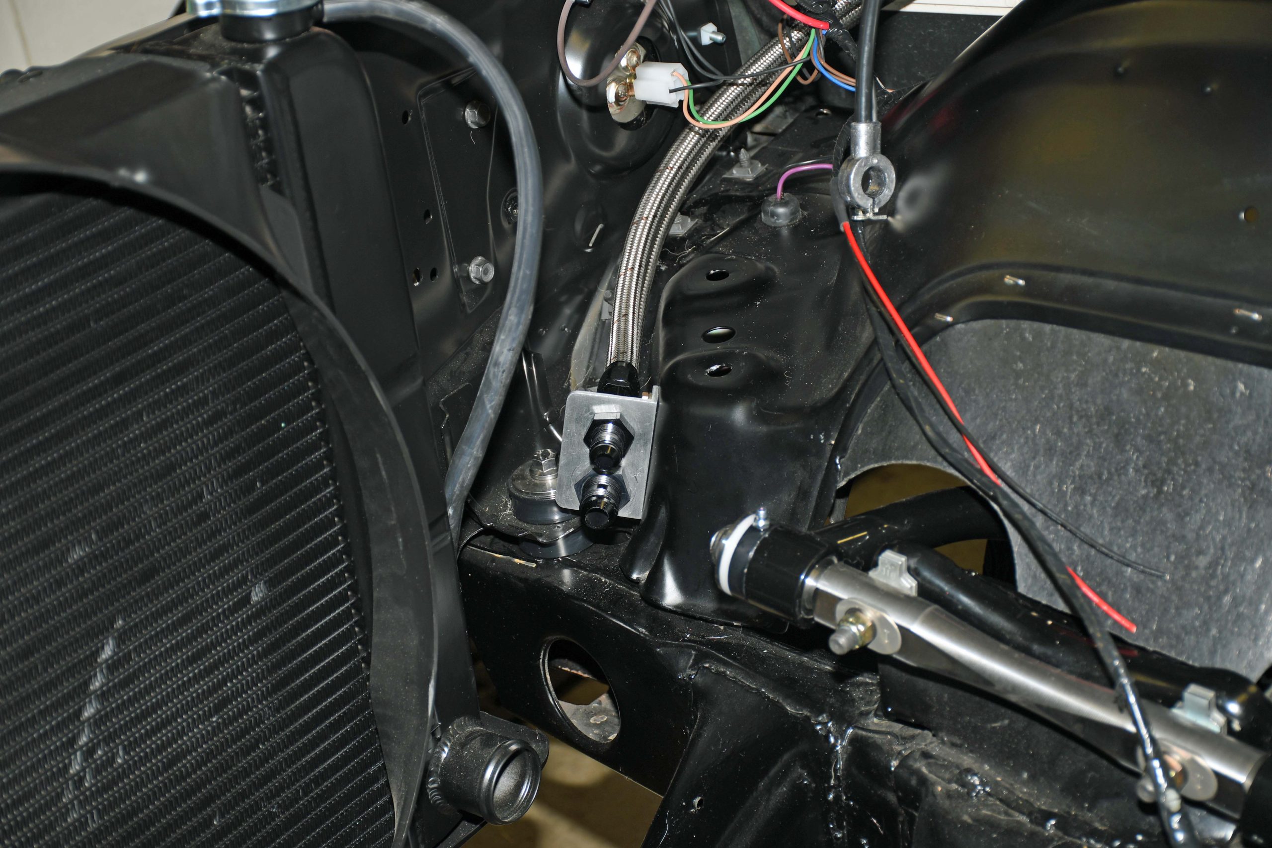
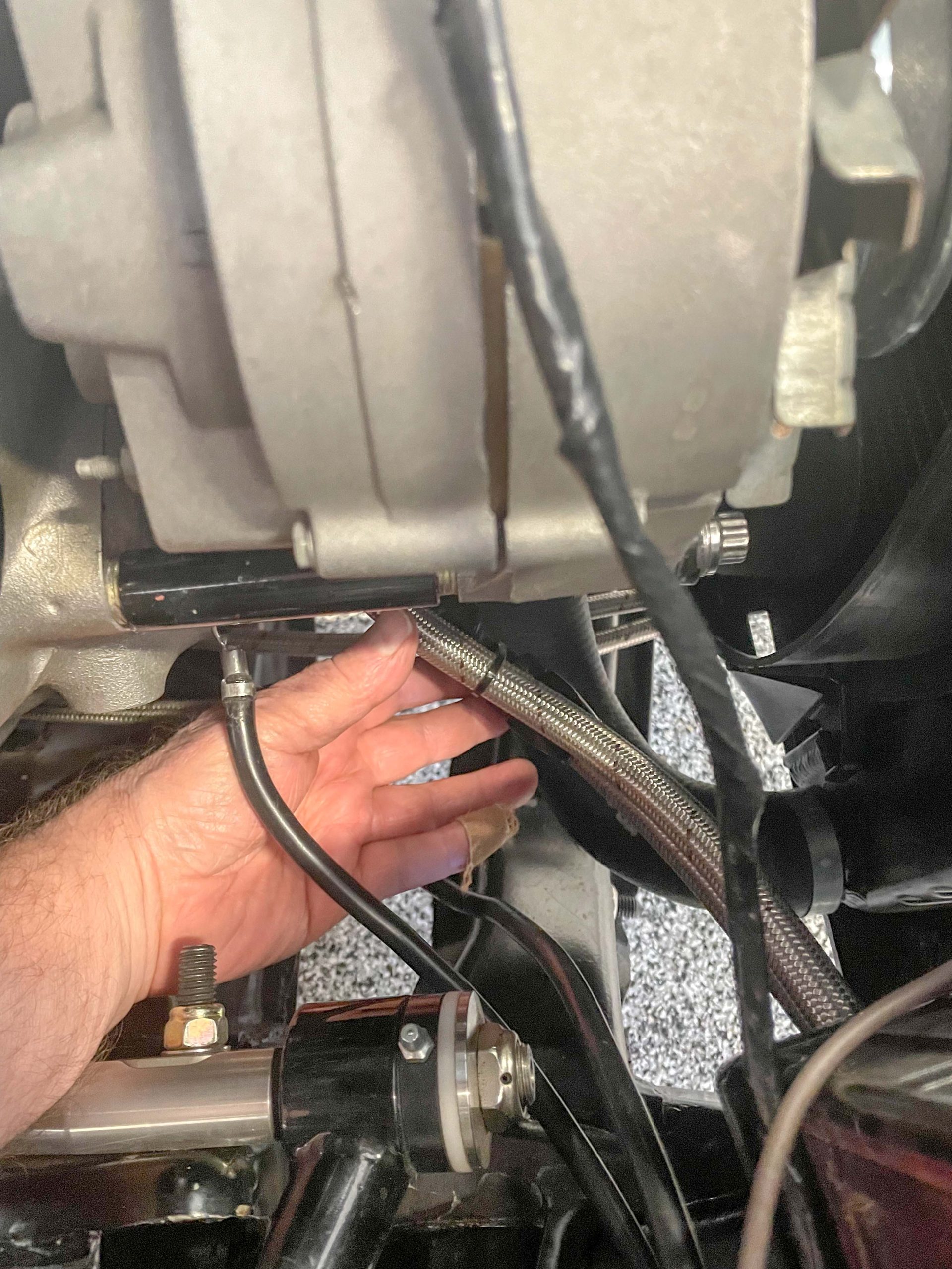
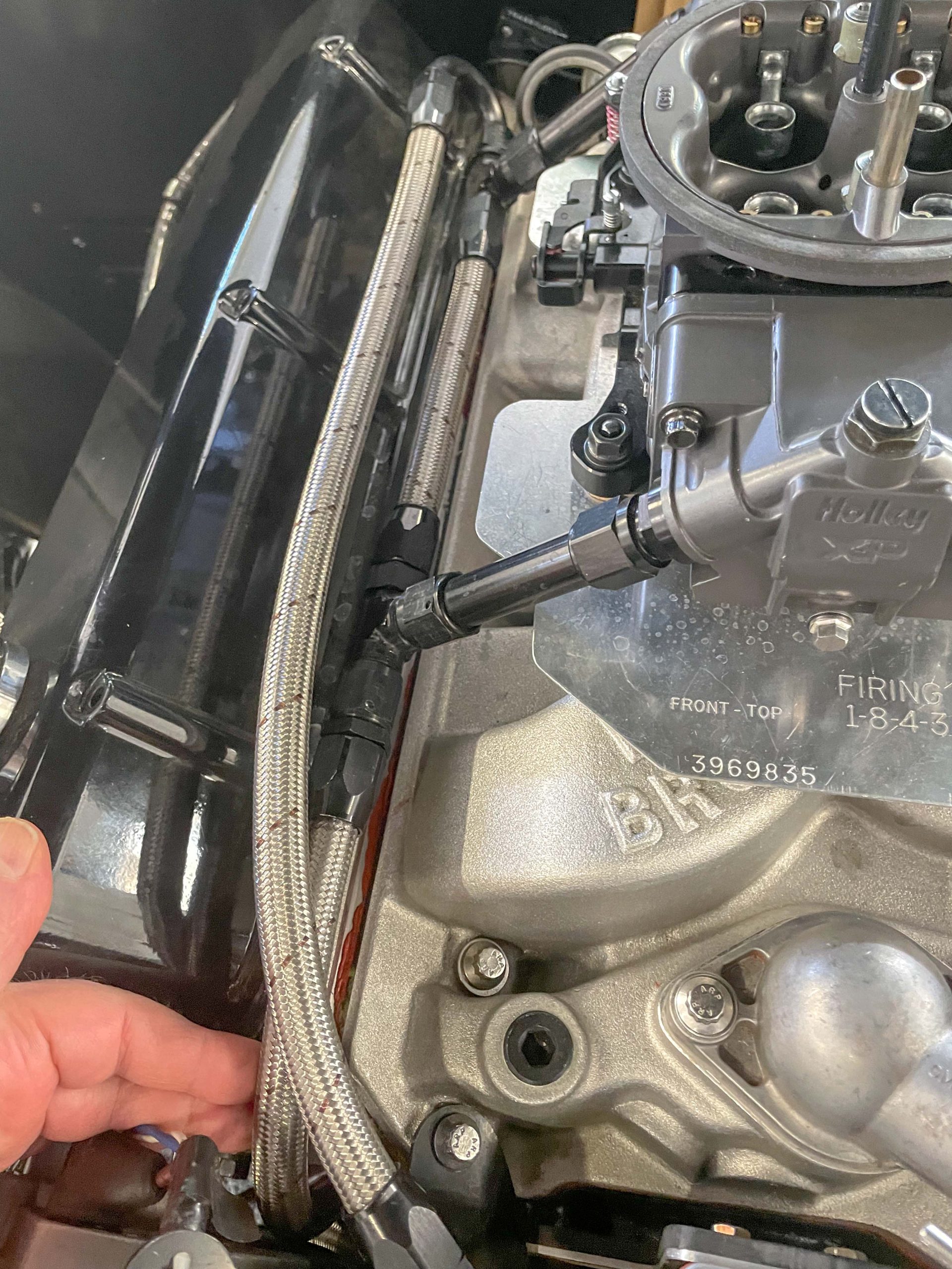
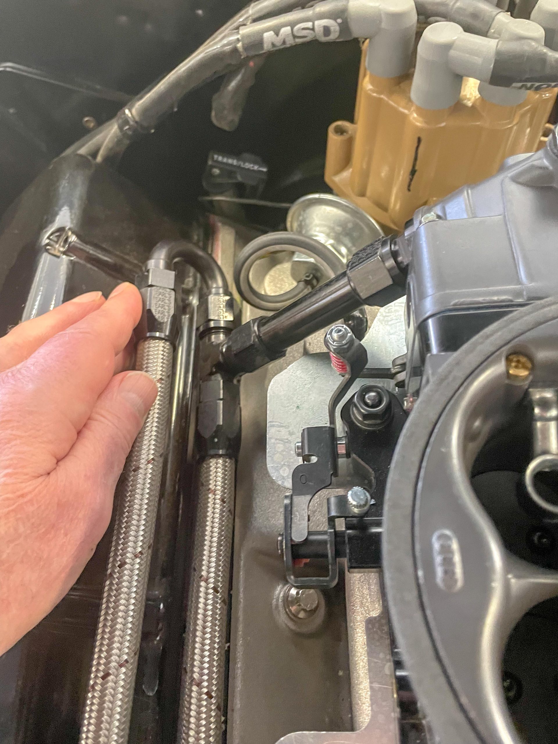
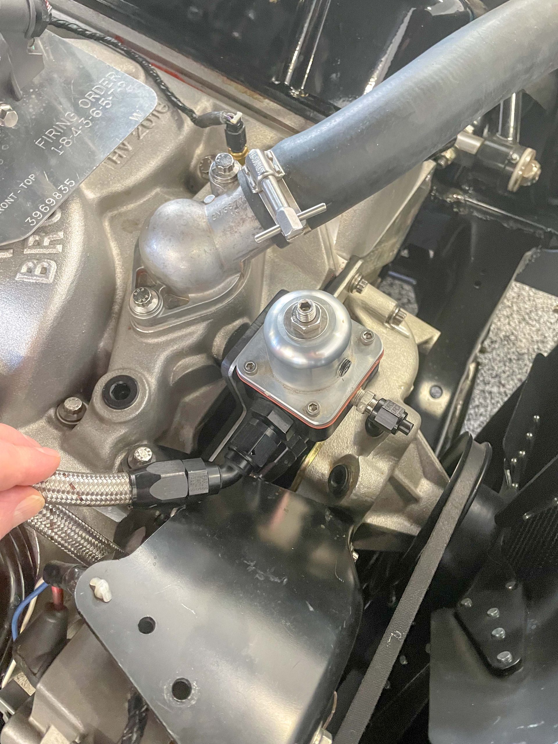
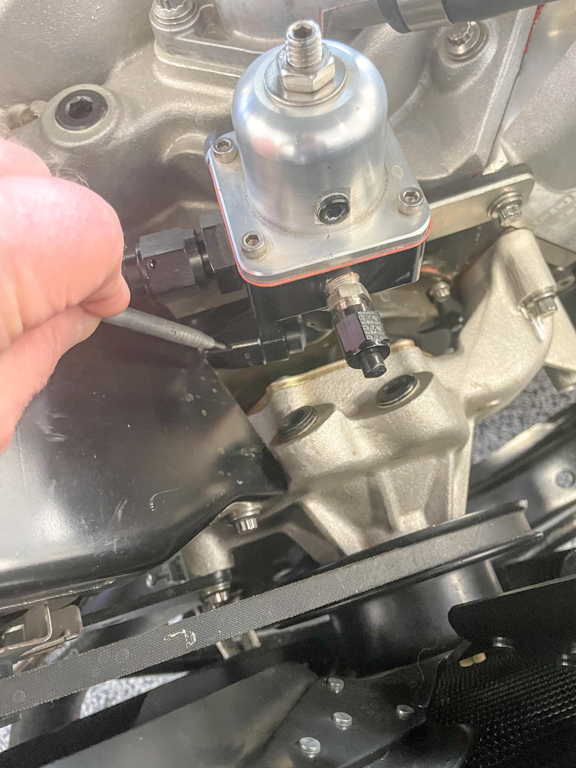
The ideal plumbing arrangement in a big power street-strip application has the bypass regulator mounted in a return line positioned shortly after the carburetor (see the accompanying photos). This allows the fuel to flow through the carburetor before it reaches the regulator. Fuel pressure is still regulated, however. In many cases, you’ll need to step down the fuel line size before the carburetor. It’s simply not practical to plumb -10 AN hose directly to the carb bowls. Here, -8 AN is usually the practical limit.
Engine Performance with a Bypass Fuel Regulator
When you compare a bypass system such as this to a deadhead setup, you’ll find it produces a more stable and much smoother fuel pressure curve. Because the supply of fuel is constantly circulating throughout the fuel system, the bypass regulator can respond much quicker to changes in the engine load. This means the fuel bowls are always full and it also lessens the chances of lean out conditions, particularly on a race track. Of course, the other benefits found on fuel injected cars also apply: The fuel isn’t heated, the pump isn’t overworked, the regulator isn’t getting hammered on and off, and there is no pressure creep.
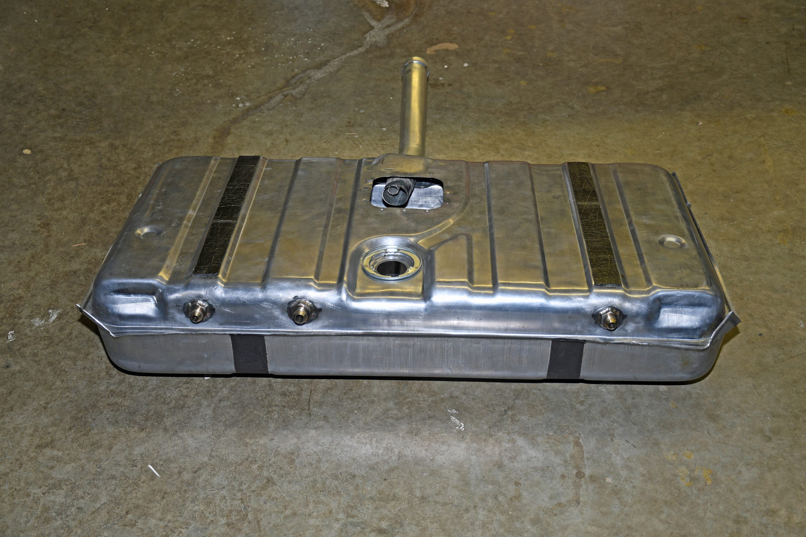
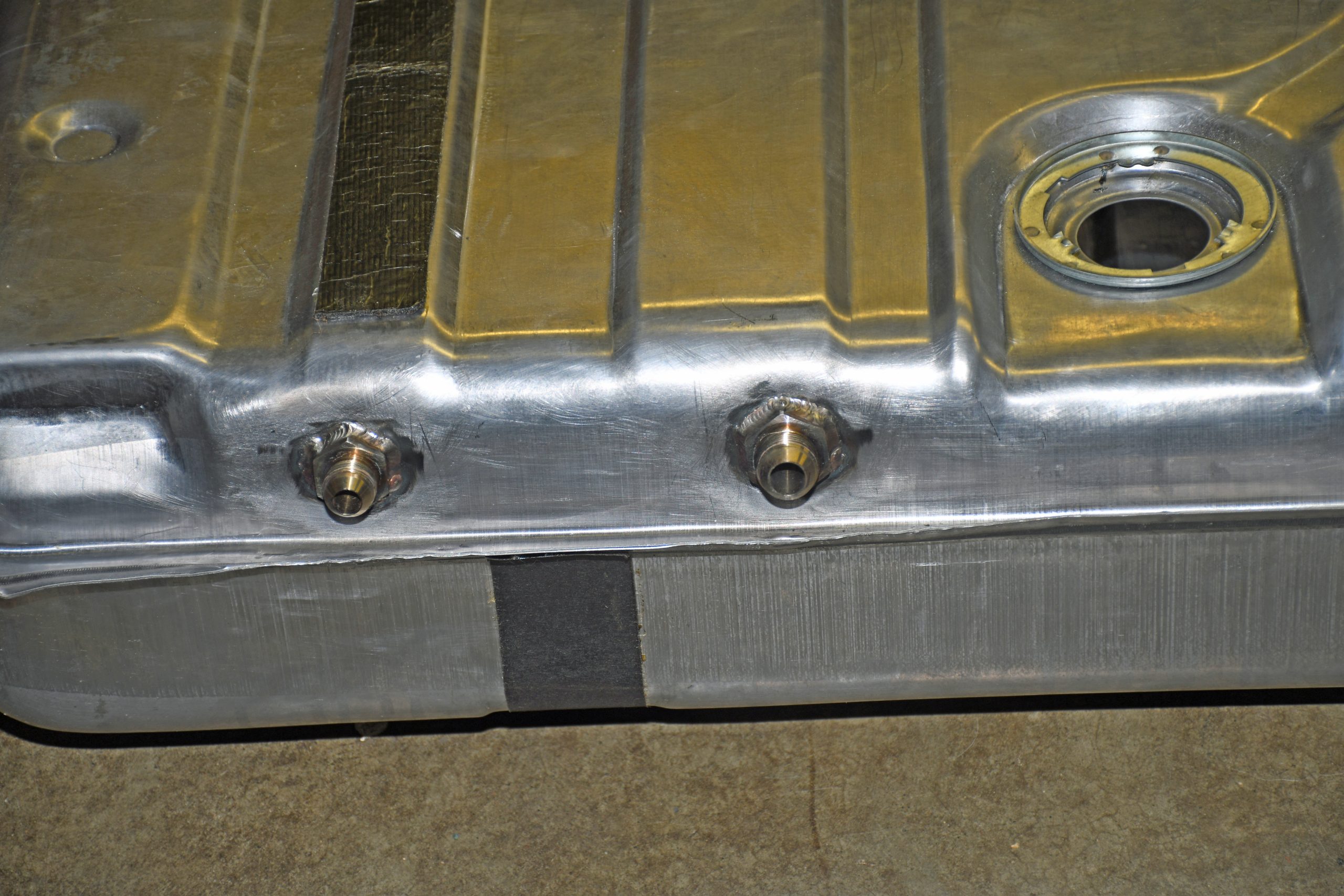
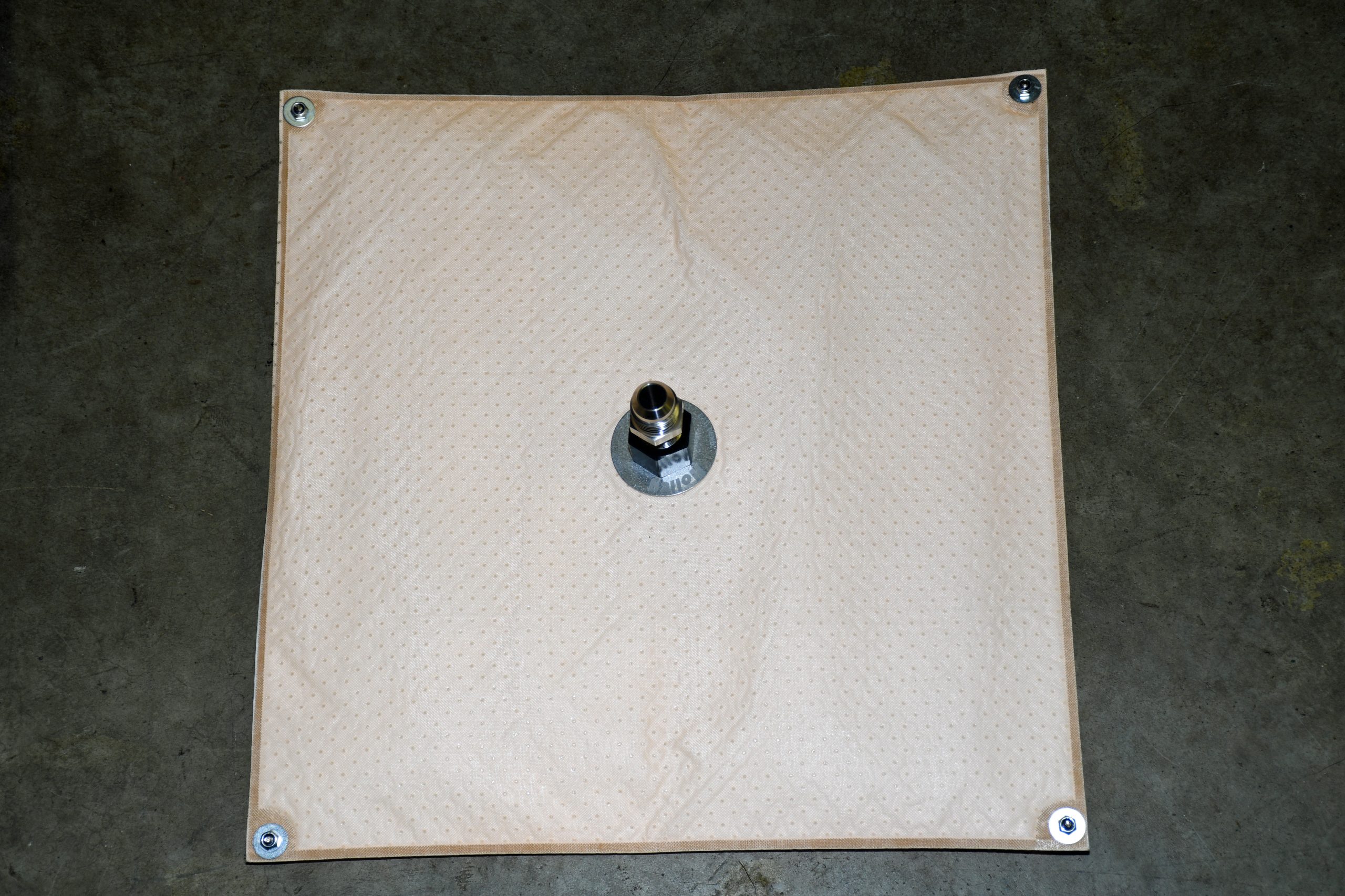
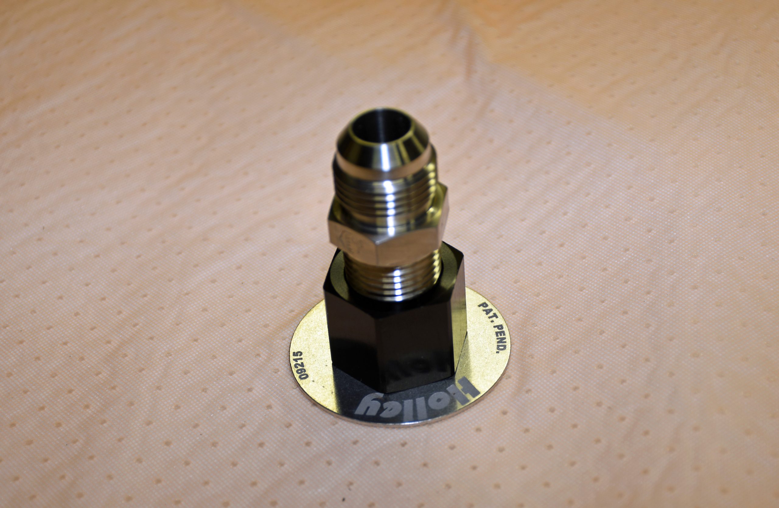
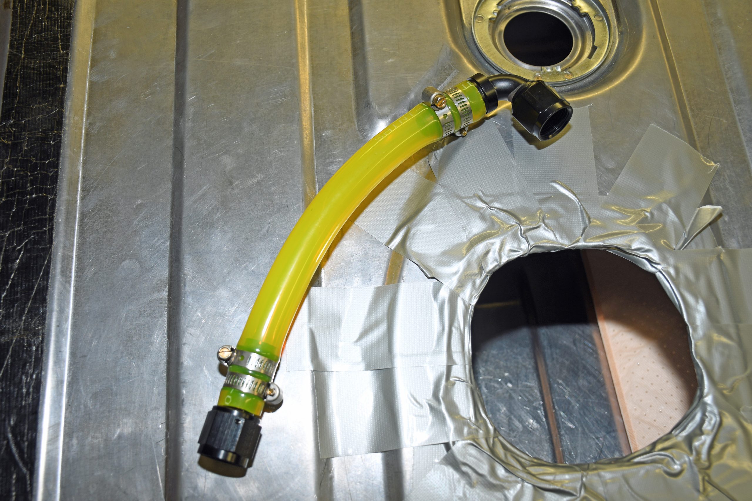
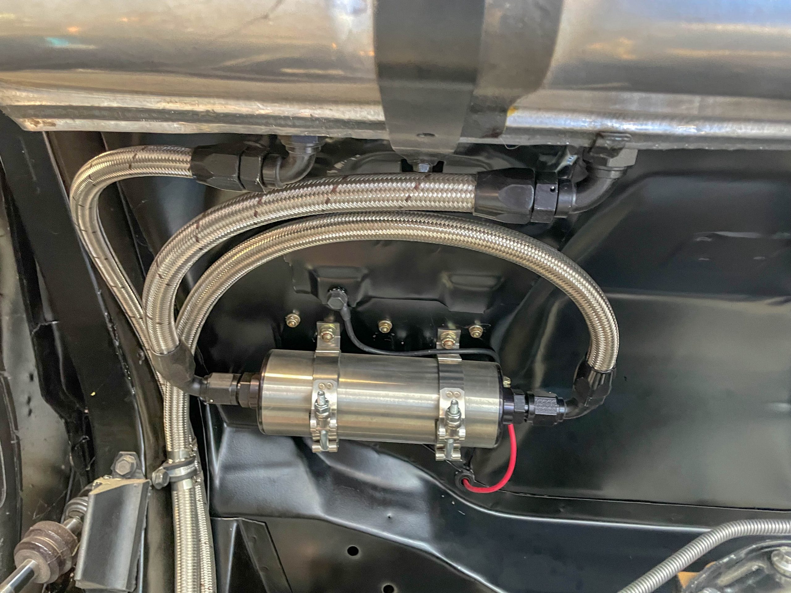
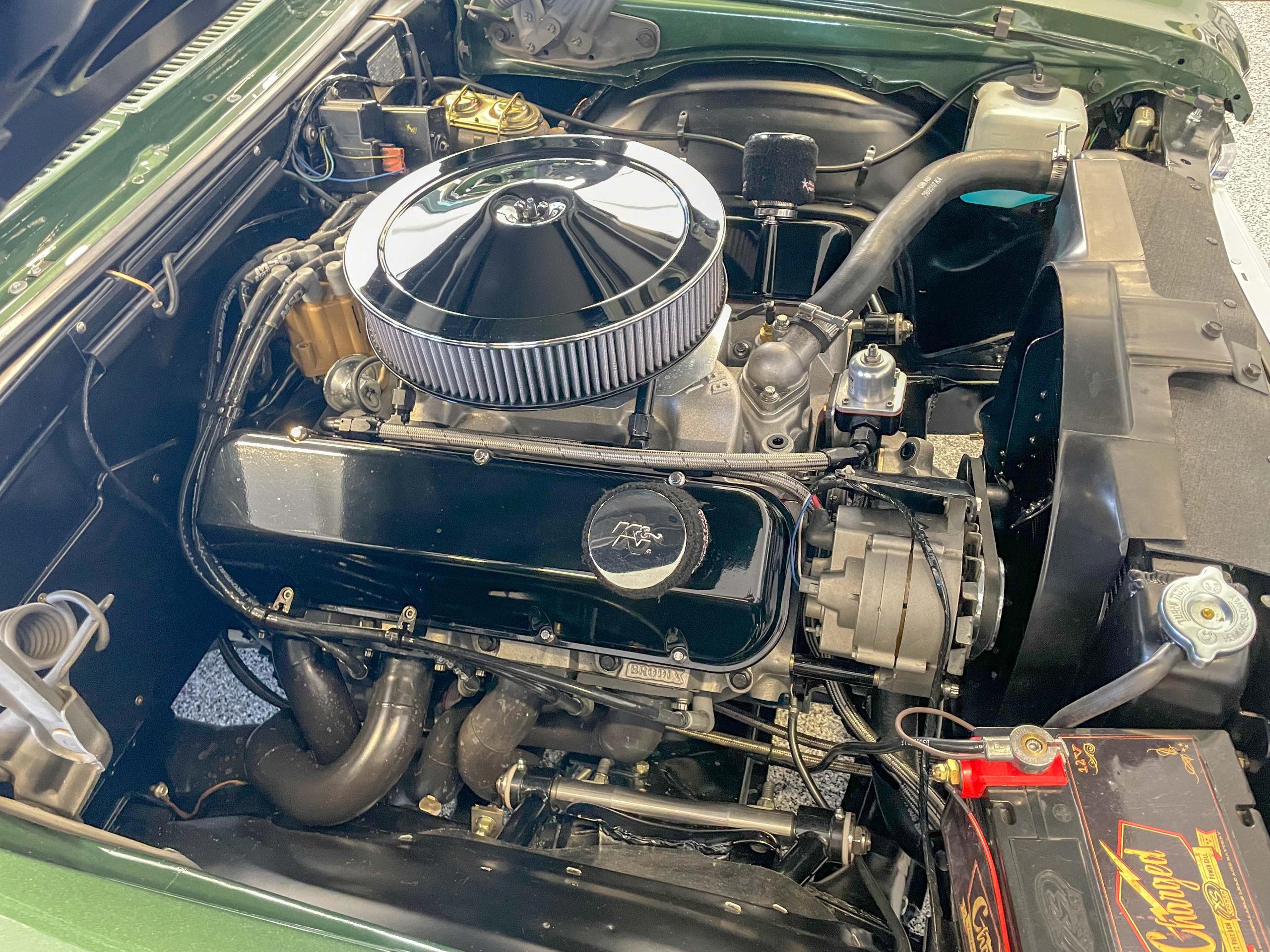
In my own car (shown in the accompanying photos), the components incorporated all came from the SummitRacing.com, and they include a Weldon A-600-A inline electric fuel pump, a Weldon 2040-2810-A-15 regulator and a mix of -10AN and -8AN Earl’s Performance fuel line. The tank is equipped with a Holley 16-107 Hydramat with a 1/2-inch NPT pickup (adapted to -10 AN). There are bulkhead fittings welded to the tank: a -10AN supply, a -8 AN return and a -8 AN vent. I use a non-vented gas cap.
The Weldon pump will easily pull a prime and as a result, the pump does not need to be mounted lower than the fuel-level in the tank. This makes for cleaner plumbing on a street driven car. You can read my earlier story for details on the Weldon pump.
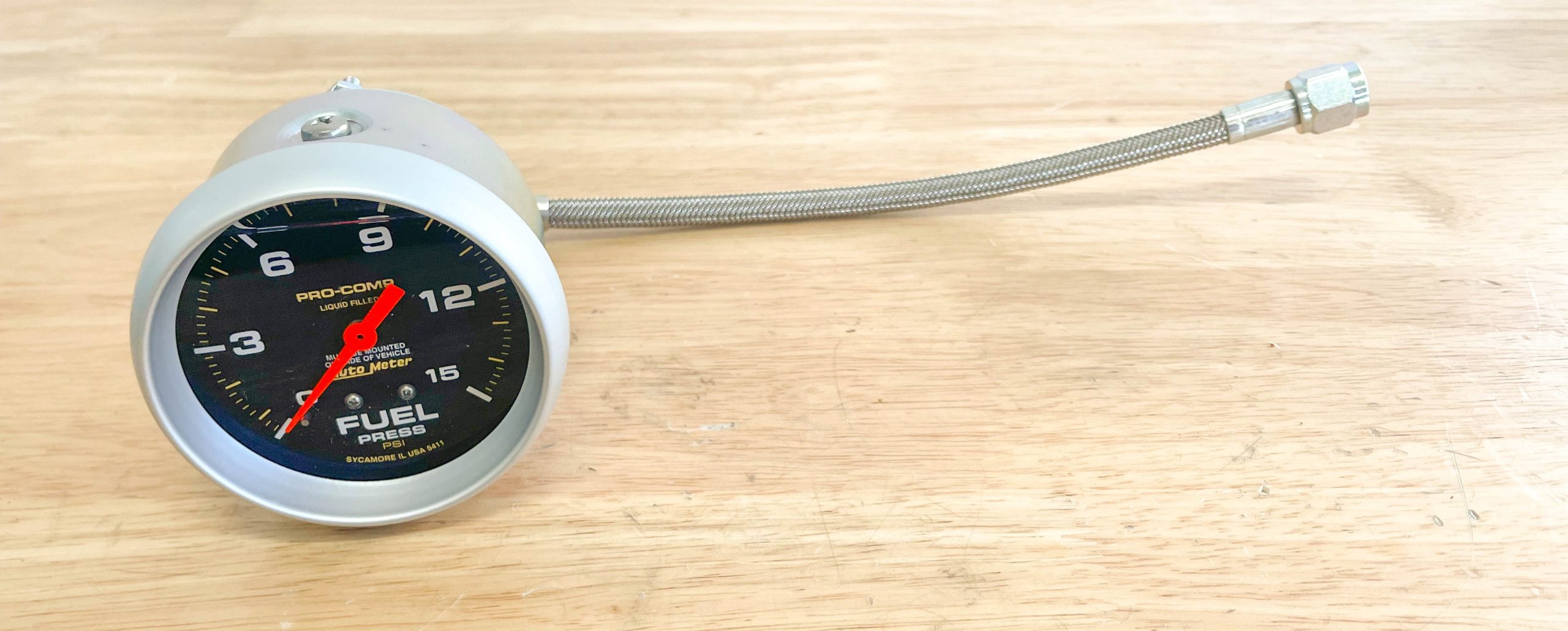
Does the system work? You bet. Fuel pressure remains constant (I have an easily removable fuel pressure gauge); I don’t fight surging float levels and even in 90+ degree heat, there are no vapor lock issues. A bonus is, pump noise is much lower than the constant moan I was accustomed to hearing with deadhead arrangements.
I got 2 questions.
Why not put the regulator under the battery tray, to keep it away from extra heat?
How did you close up the hole in the tank, where you put the mat in? I guess tig welded.