Few things befuddle us more than automotive electricity. On the surface, it appears to be black magic that does the work for us. If you study the humble light bulb, current flows across a tungsten filament—a resistor—that resists the flow of electricity enough to where it gets white hot and gives off light.
Because the filament is in a vacuum, it continues to glow until metal fatigue (the cyclic fatigue of “on” and “off”) causes it to break and the bulb burns out.
Automotive gauges work in a similar fashion and differ very little from manufacturer to manufacturer. The basic principles are the same.
With the exception of mechanical speedometers on older vehicles*, which are mechanically driven, instruments operate on resistance to the flow of electricity to negative ground, which determines where the needle moves on the instrument face.
Fuel, temperature, and oil pressure gauges all work on the same principle of current flow to ground.
* You may also encounter aftermarket mechanical temperature gauges too, read the distinction here: What’s the Difference Between a Mechanical & Electrical Temperature Gauge?
With automotive electrical systems, we have a single hot wire (positive) that provides power to the lamp or accessory. The second wire (neutral) is the car’s body, also known as “negative ground,” which carries electricity back to the battery to complete the circuit.
Think of the body and chassis as part of the electrical path. Instead of having a wire back to the battery, we use the body and chassis. This is what we mean by “negative ground.”
Current flows from the battery’s positive post to the lamp or accessory to ground and back to the negative post via the car’s body and negative battery cable.
With most classic muscle cars, the battery’s negative cable is connected to the engine block. Because the engine block is insulated from the body by rubber engine mounts, it must be grounded to the car body/chassis via a ground strap between the cylinder head/block and firewall.
Without the ground strap, weird electrical gremlins will plague us—dim and flickering lights, erratic accessory operation, engines that won’t start or will stall. There can be a brownish glow in lamps that should not be lit due to a bad ground because electricity will always find a path.
Keep all of this squarely in mind during electrical system troubleshooting.
Instruments—How They Work
Instruments and warning lights function by the same principles of automotive electricity we’ve just described. Switches operate like water faucets. They are electricity traffic cops that start and stop the flow. Turn off the switch (open circuit) and the flow of current stops. Switch the switch on (closed circuit) to get current flow.
Volume controls and dimmer switches are current flow regulators—controlling the flow of electricity through the circuit. When you think of electricity, there are two basic ways to look at how it is measured. Current (amps) is electrical pressure, or how much “push” we have behind the electricity. Voltage is volume, or how much electricity we have.
Resistance to current flow is known as ohms or impedance. The higher the ohm reading, the more resistance we have to current flow. The more resistance we have, the less power we have to or from an accessory or lamp. With resistance comes heat as a result of the current flow traffic jam.
Fuel, oil pressure and coolant temperature gauges operate based on how much power is flowing through each gauge. The more power flows through the gauge, the higher the needle will read by regulating the flow of electricity through the gauge.
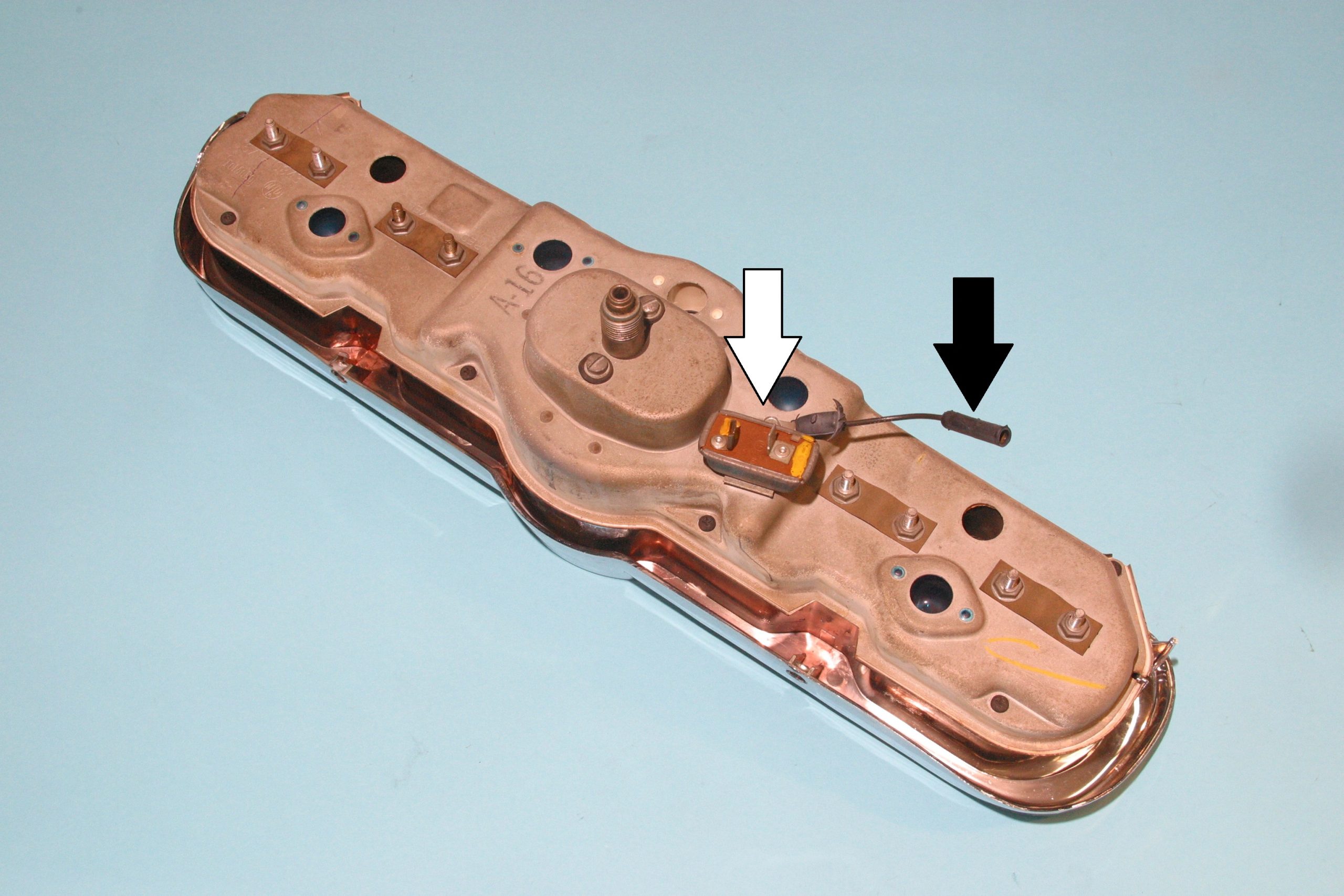
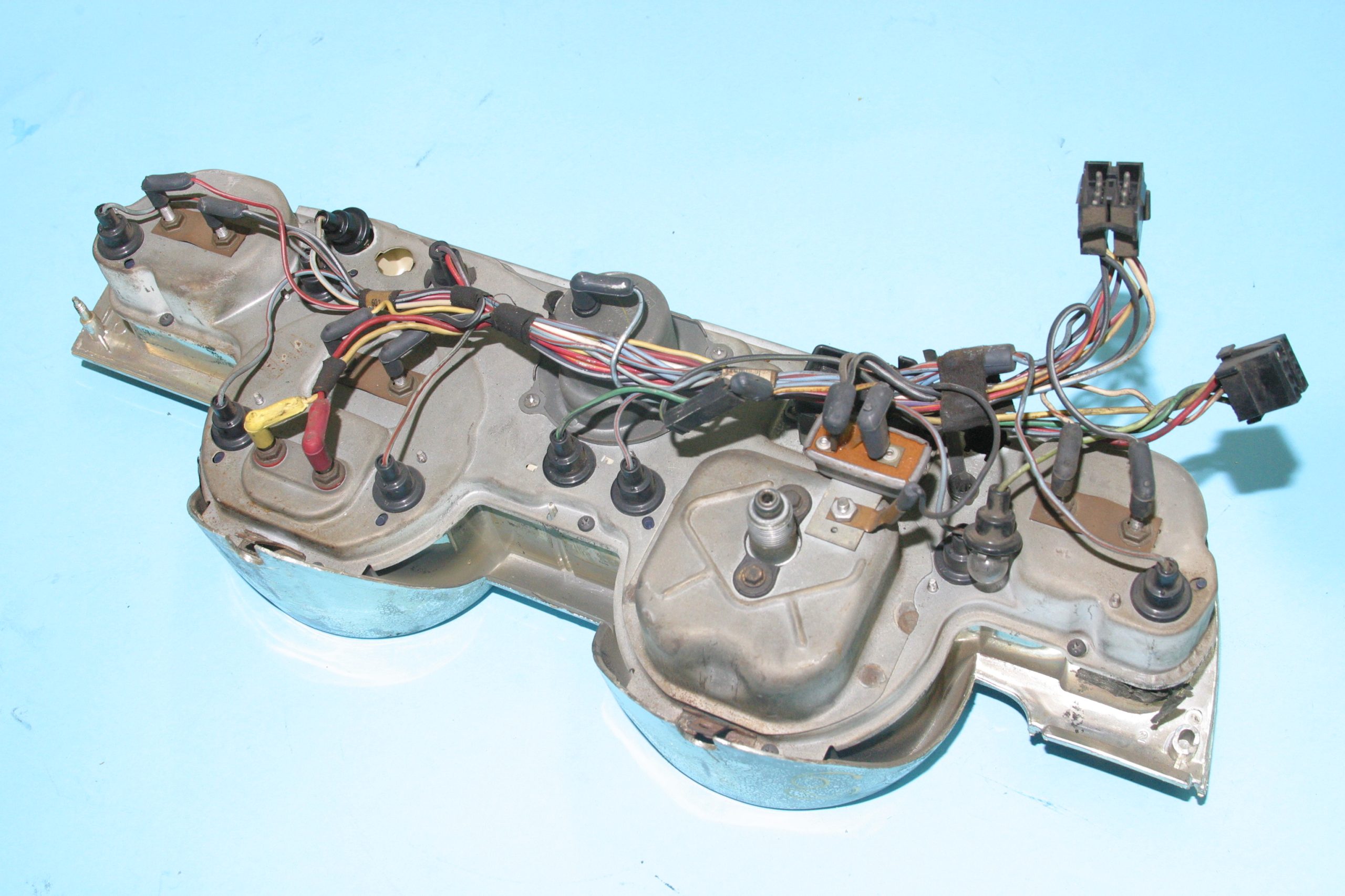
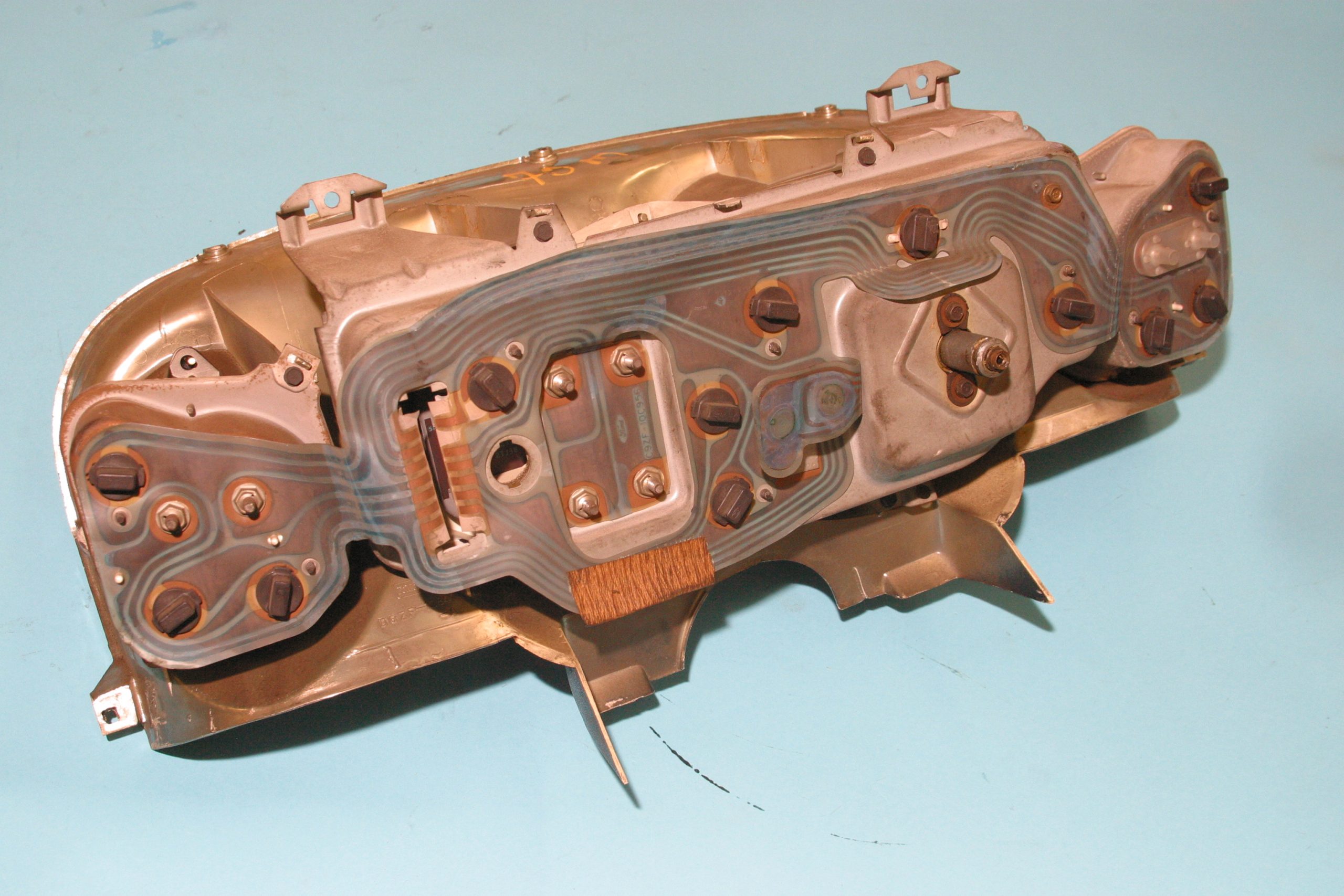
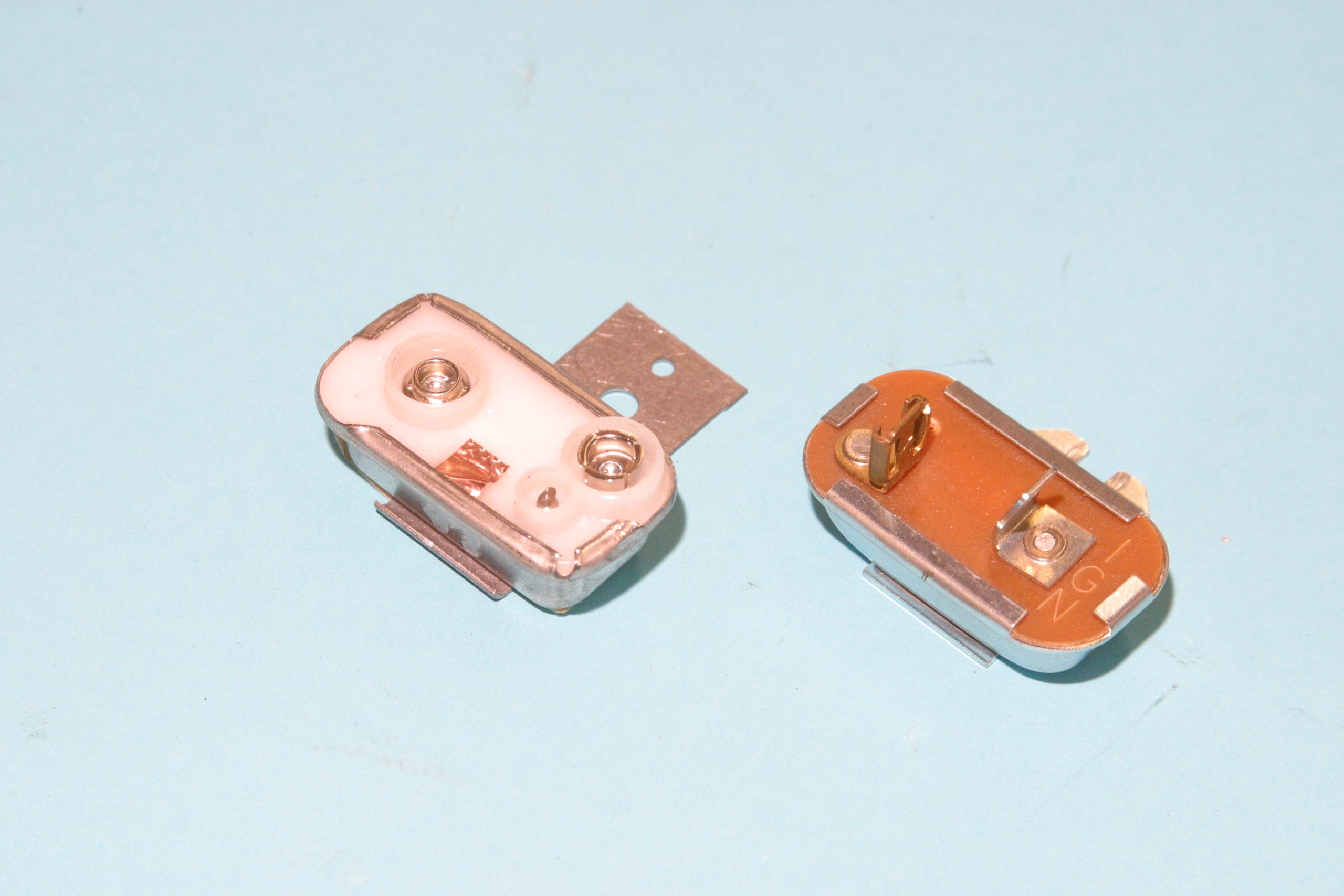
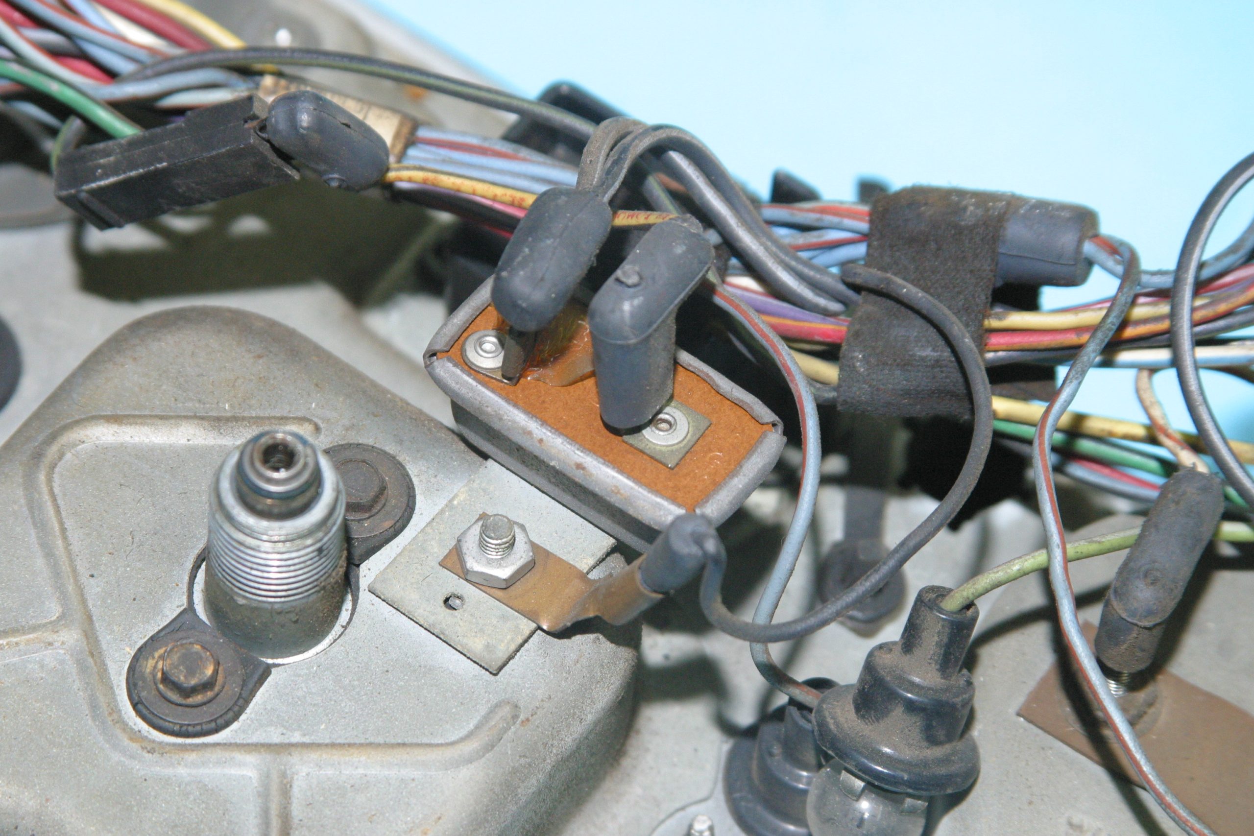
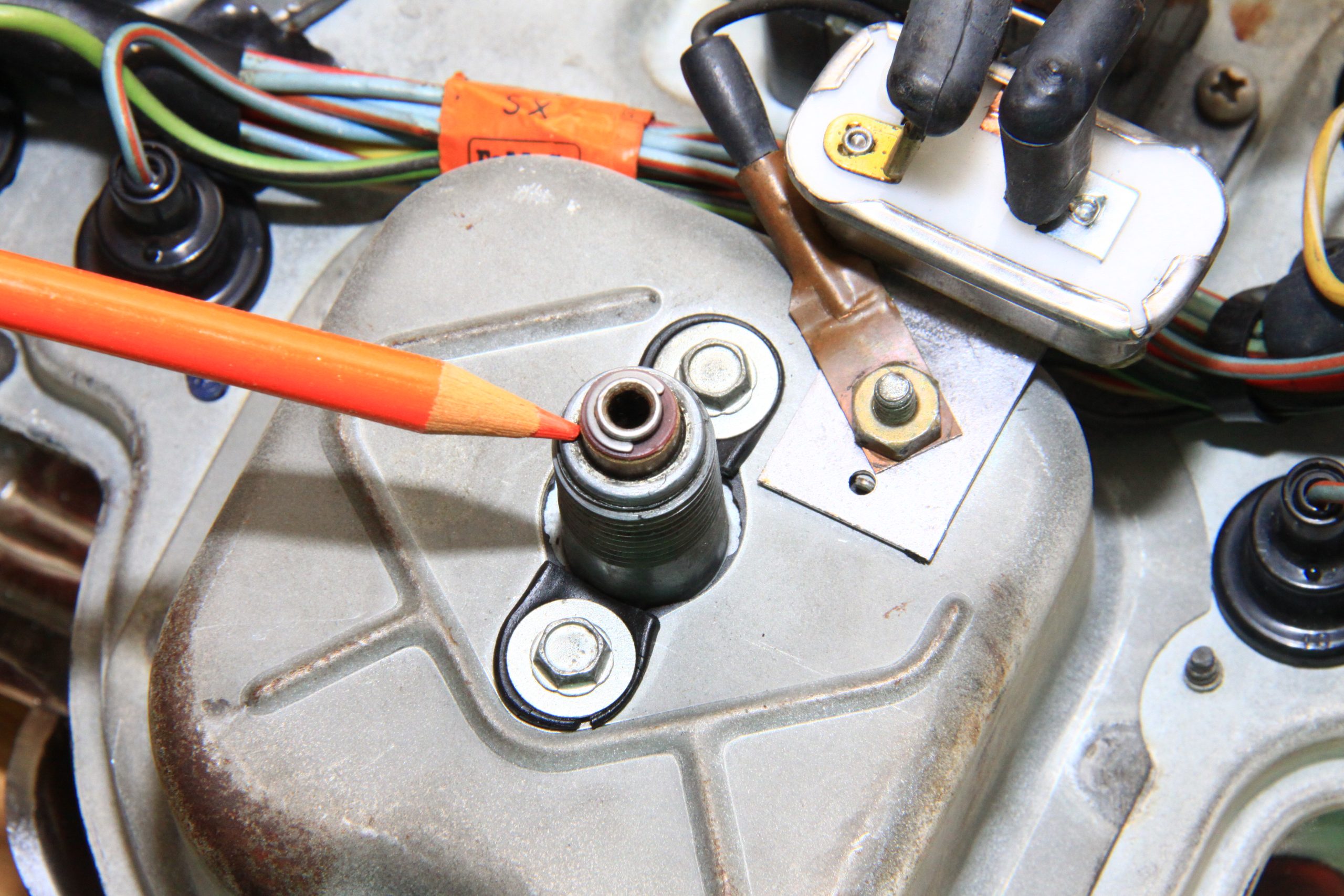
On the back of most instrument panels is the voltage limiter (also called an instrument voltage regulator). When you turn the ignition on, roughly 12 to 14 volts of electricity flow to the voltage limiter. The voltage limiter reduces that 12 to 14 volts to approximately five volts which is what instruments must have.
With five volts flowing to the instruments, it is a matter of completing the circuit from the gauge to negative ground, which is how we know how full the fuel tank is, what engine coolant is, or what there is for oil pressure. Fuel, coolant temperature, and oil pressure all get their feedback the same way—from variable resistance to ground through a sender.
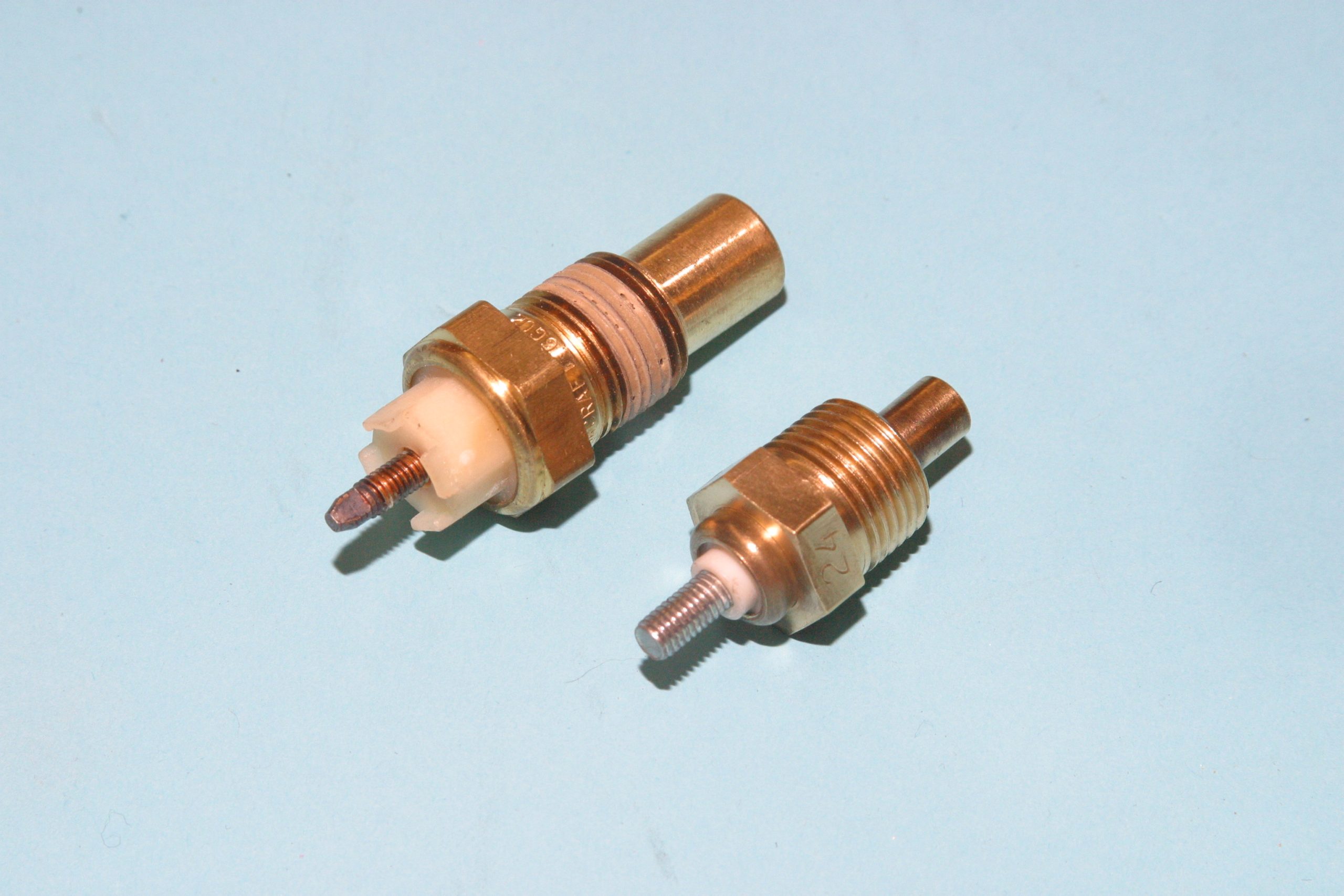
Each type of sender or sending unit works differently, but they all do the same thing. They vary resistance to ground.
The sending unit is a variable resistance switch to ground, which operates like a stereo volume control or a dimmer switch. The volume control and dimmer switch control resistance from the hot wire to negative (neutral) while automotive sending units control resistance to negative ground. When resistance to ground is high, the instrument will read low. When resistance is low, the needle will read high.
We explore gauge sending units (and their mechanical pressure/temperature equivalents) in more detail in this article: What is a Sending Unit?
Fuel Level, Pressure & Temperature Gauges
In the fuel tank, the sending unit gets its input from the float, which is tied to a variable resistor via the float arm. When the tank is full, resistance through the sending unit’s variable resistor is low and there’s maximum current flow across the gauge. The needle moves to the “full” mark.
As the tank loses fuel, the float drops and resistance across the variable resistor (sender) increases, just like turning down the volume or dimming the lights. The needle moves toward “empty.”
When you’re getting an erroneous reading on a fuel gauge or no reading at all, check power to the instrument first. There should be roughly five volts. If there is power, the sending unit is probably at fault. If the gauge doesn’t work at all, the sending unit probably isn’t completing the circuit to ground.
Disconnect the fuel sending unit and ground the plug directly to ground (the body). Watch the fuel level gauge for operation. If the needle goes to full, the sending unit is faulty. If the gauge does not respond, there is a break in the wiring between the fuel gauge and the sending unit.
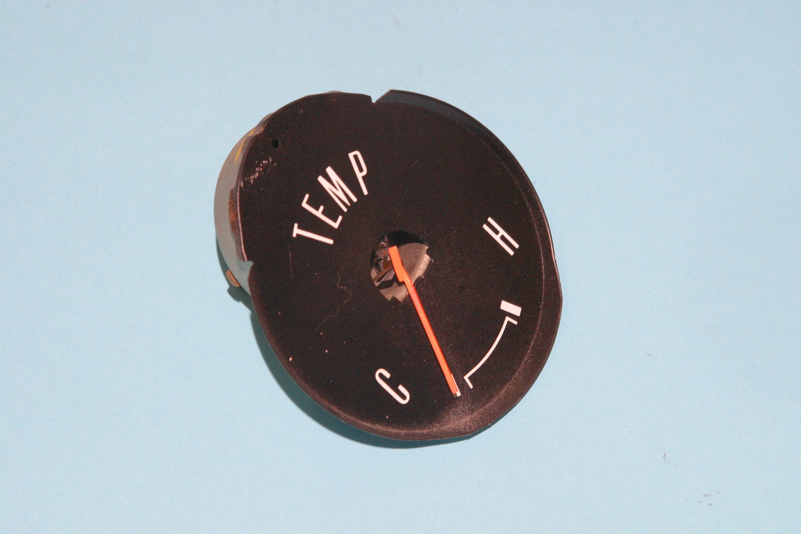
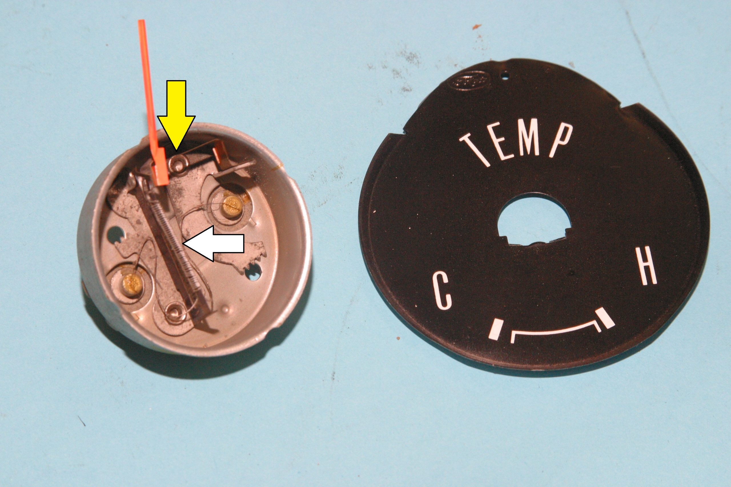
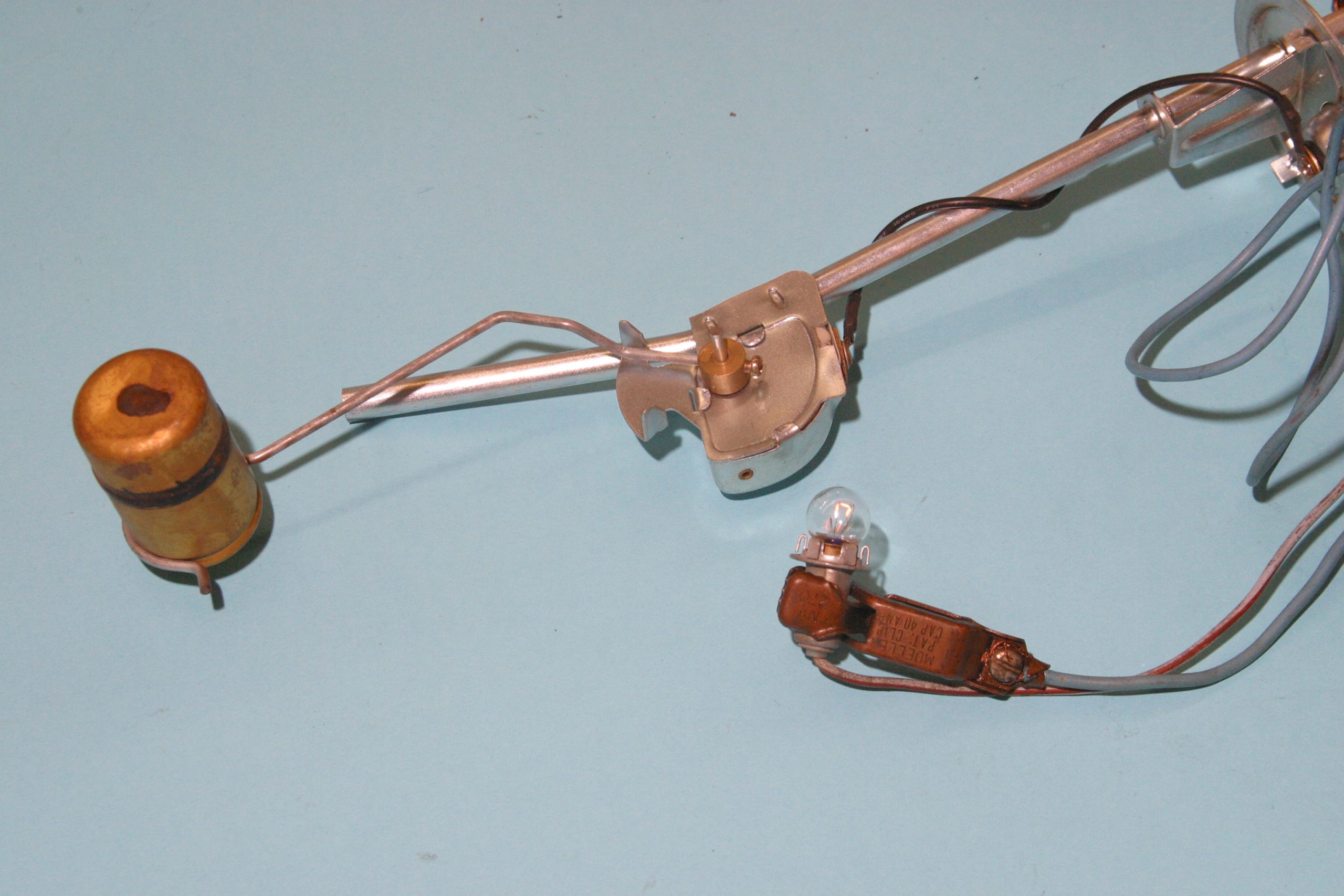
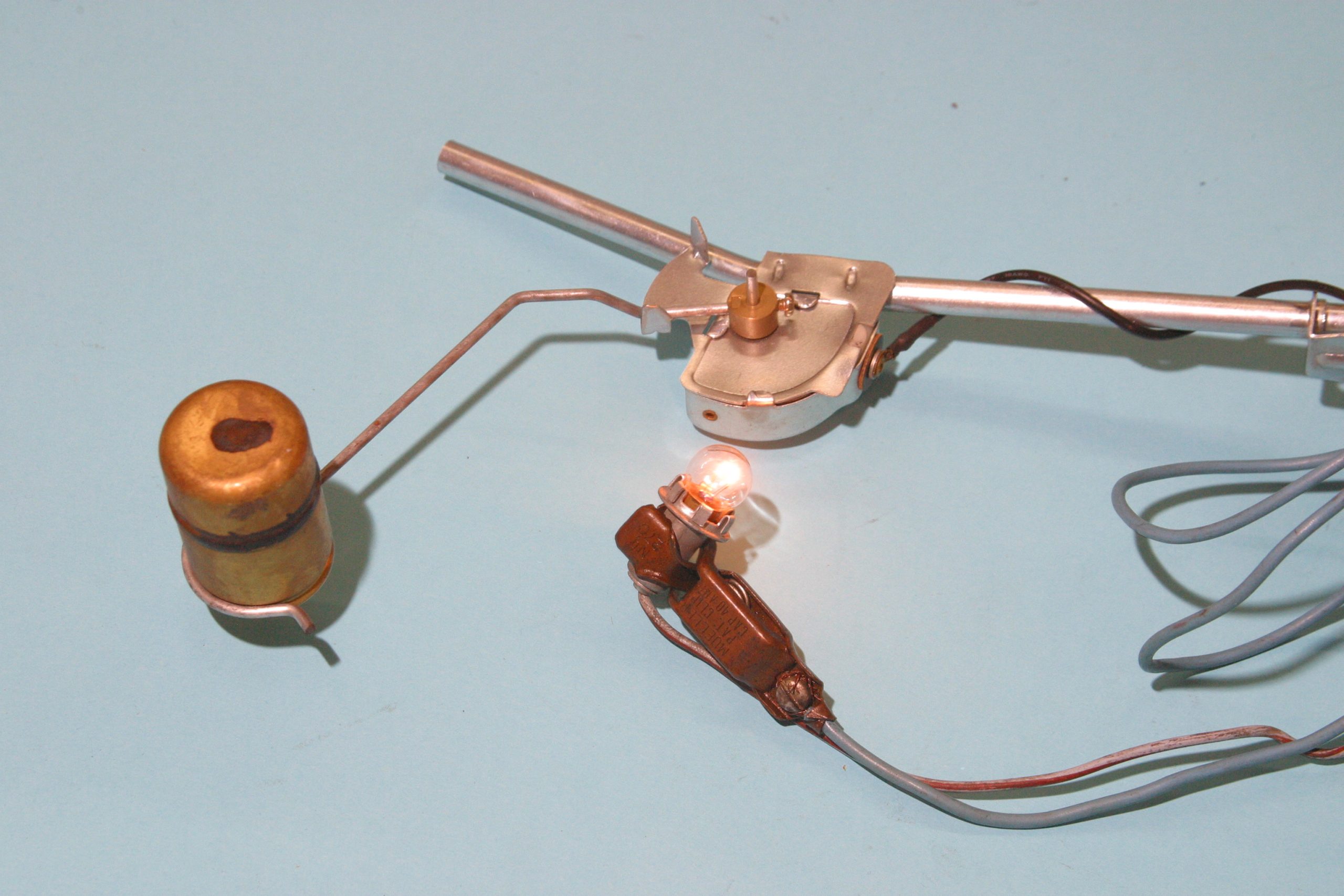
The coolant temperature gauge works just like the gas gauge only it is screwed into the engine’s water jacket. The coolant temperature gauge operates based on the amount of current flowing to negative ground. We control ground resistance from the temperature gauge through the sending unit. Inside the sending unit is a variable resistor just like we have in the fuel tank.
The variable resistor in the temp sender is controlled by water temperature and a bimetallic contact. As the engine warms, the bimetallic contact moves across the resistor. And as the engine warms, there is less resistance to ground. The TEMP needle moves toward maximum. If everything is working properly, the needle will climb into the normal zone. If the engine overheats, there is even less resistance across the sending unit to ground, driving the needle toward “H.”
If the coolant temperature sending unit is bad, the temperature gauge will be either inoperative or it will climb to “H” and stay there. Two things can happen to a sending unit. Corrosion inside causes too much resistance, rendering the gauge inoperative. Or there is no resistance, driving the gauge to maximum. As with the fuel gauge, check for power to the temperature gauge first.
Like the fuel and coolant temperature gauges, the oil pressure gauge reads based on the amount of current flowing to ground. The oil pressure sending unit has a spring-loaded piston and floating contact inside. The piston moves the contact back and forth across a variable resistor. Power flows through the contact across the resistor to ground where the sender is screwed into the oil galley passage.
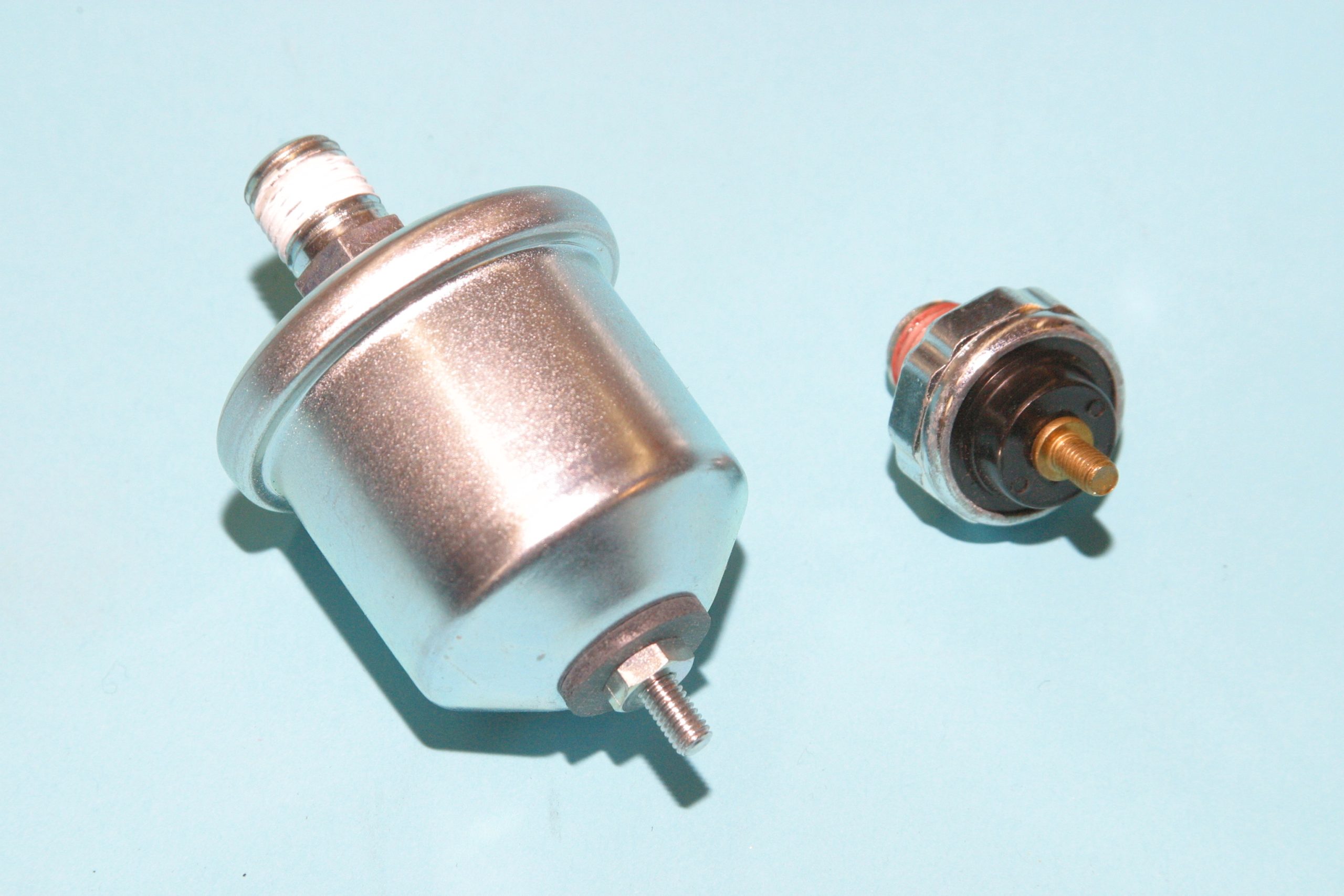
When there’s no oil pressure, there is high resistance across the sender, which leaves the needle at the “L” side of the gauge. Fire the engine and put oil pressure to the sender and contact moves across the resistor to a lesser resistance value, which increases the flow of electricity to ground from the gauge. The needle moves towards “H.”
When an oil pressure gauge isn’t working, most of the time it’s a faulty sending unit or severed lead to the sender. There may also be no power to the gauge due to a faulty voltage limiter or break in the wiring. When in doubt, ground the lead and watch the gauge. It should max out the instrument.
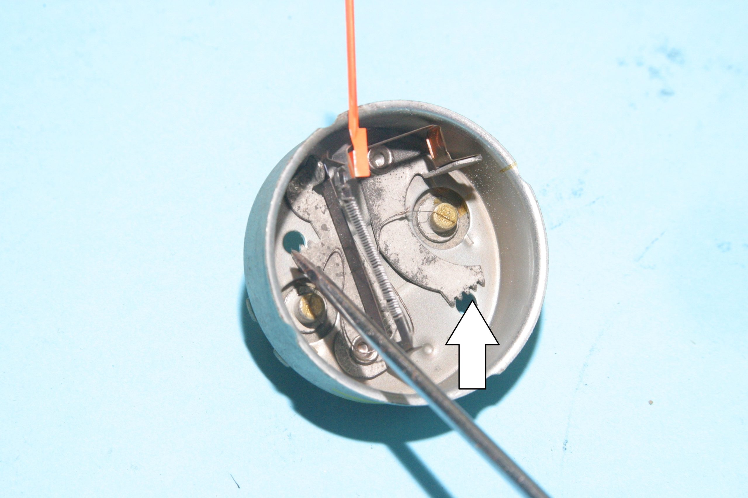
What makes the needle move? Each instrument has a heating element (a resistor), which applies heat to a temperature sensitive spring connected to the needle. When resistance at the sending unit is low and current flow across the heating element is high, heat causes the spring to move the needle higher.
By contrast, when resistance at the sender is high and current flow is low, the heating element is cooler and the needle rests.
Ammeters Are Different — And Dangerous
Instead of operating on variable resistance as fuel, coolant, and oil pressure gauges do, the ammeter operates based on current flow in and out of the battery. When there’s current flow out of the battery, the ammeter needle will swing left to discharge. If there’s current flow from the alternator/generator into the battery, the needle will swing right of center toward charging.
Chrysler/Plymouth/Dodge ammeters are very sensitive. As the turn signal blinks on and off, the needle is all over the place. Ford ammeters, by contrast, don’t seem to move at all. In fact, most Ford ammeters burned out and stopped functioning in the first year of operation.
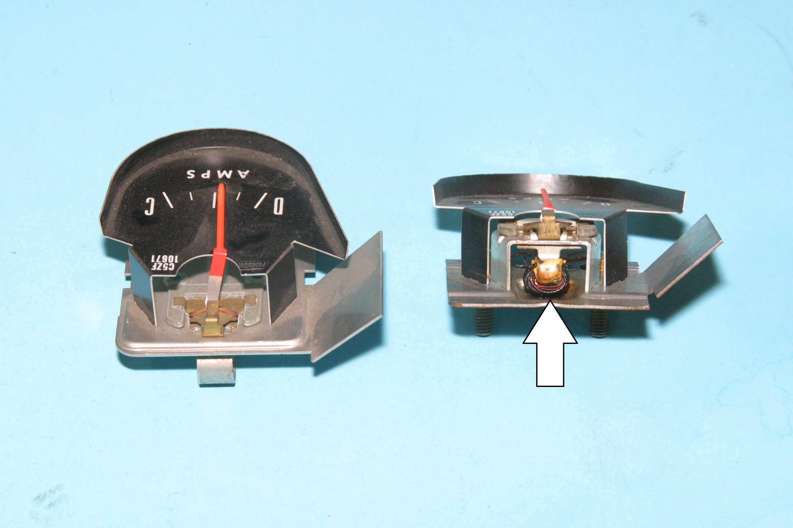
What makes ammeters “dangerous” is they are live all of the time whenever the battery is connected and there’s no circuit protection. This means the ammeter is “live” with the ignition off. When there is no current flow in either direction and the battery is charged, the needle remains centered. Whenever we have current flow in either direction, the magnetic field generated by current flow through the ammeter coil moves the needle in either direction.
Where ammeters fail most is coil overheat, which is very common with Ford products. The ammeter coil can overheat and start a fire because it has power all the time and is not protected by a fuse, circuit breaker, or fusible link. This can happen only with current flow in either direction—overcharging or a short to ground.
We suggest inspection of the ammeter coil periodically to be safe. Discoloration or a burning smell is grounds for ammeter replacement or disconnection.
The best advice we can offer is to bypass the ammeter entirely.
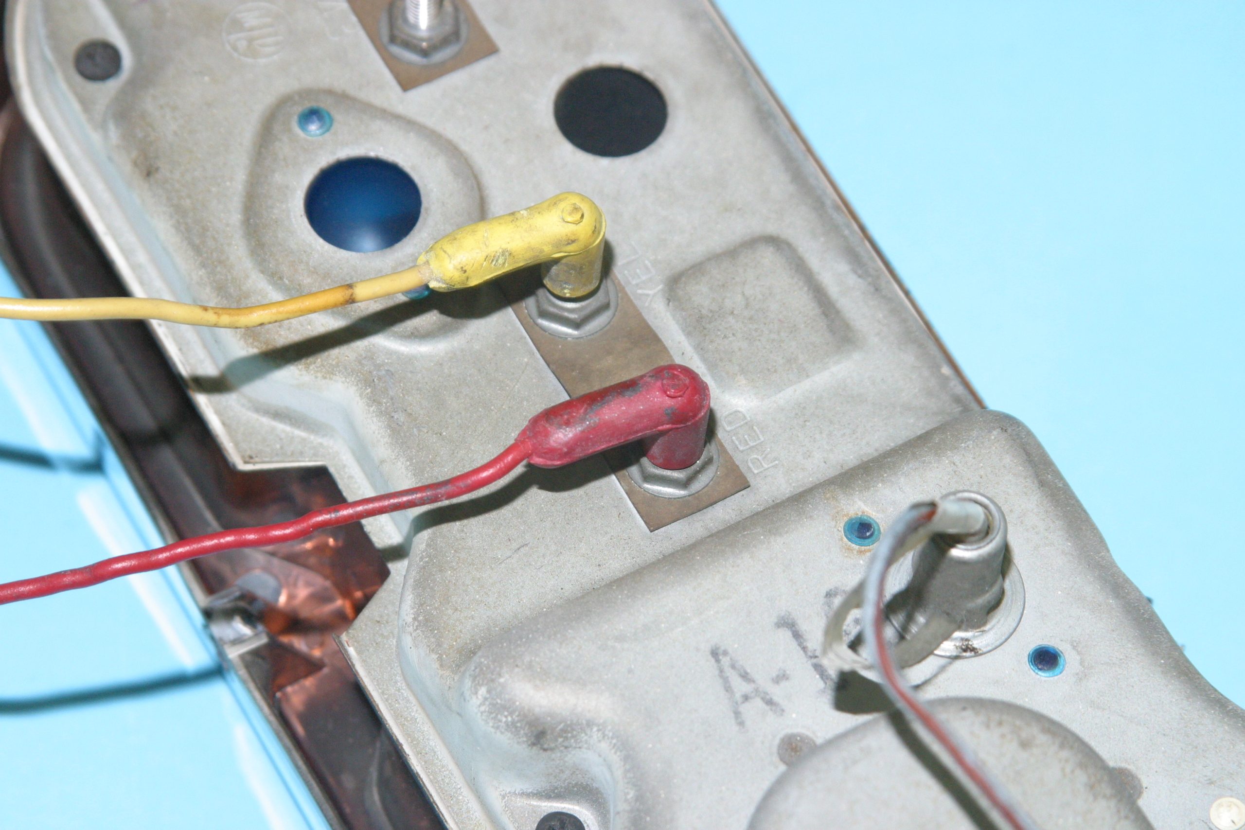
You can install circuit protection for the ammeter simply by putting an in-line fuse between the positive lead at the battery and the main power lead into the harness. Use a 20 to 30 amp fuse and 12 gauge wire. You can also install a fusible link instead of a fuse. This offers protection should the ammeter develop a short circuit. Fusible links were very common on Chrysler products back in the day.
What To Do If…
If you turn on the ignition and all of the needles max out, replace the voltage limiter behind the instrument panel. When voltage limiters fail, they either cause no resistance, which pegs the needles, or they cause an open circuit, which produces no reading at all.
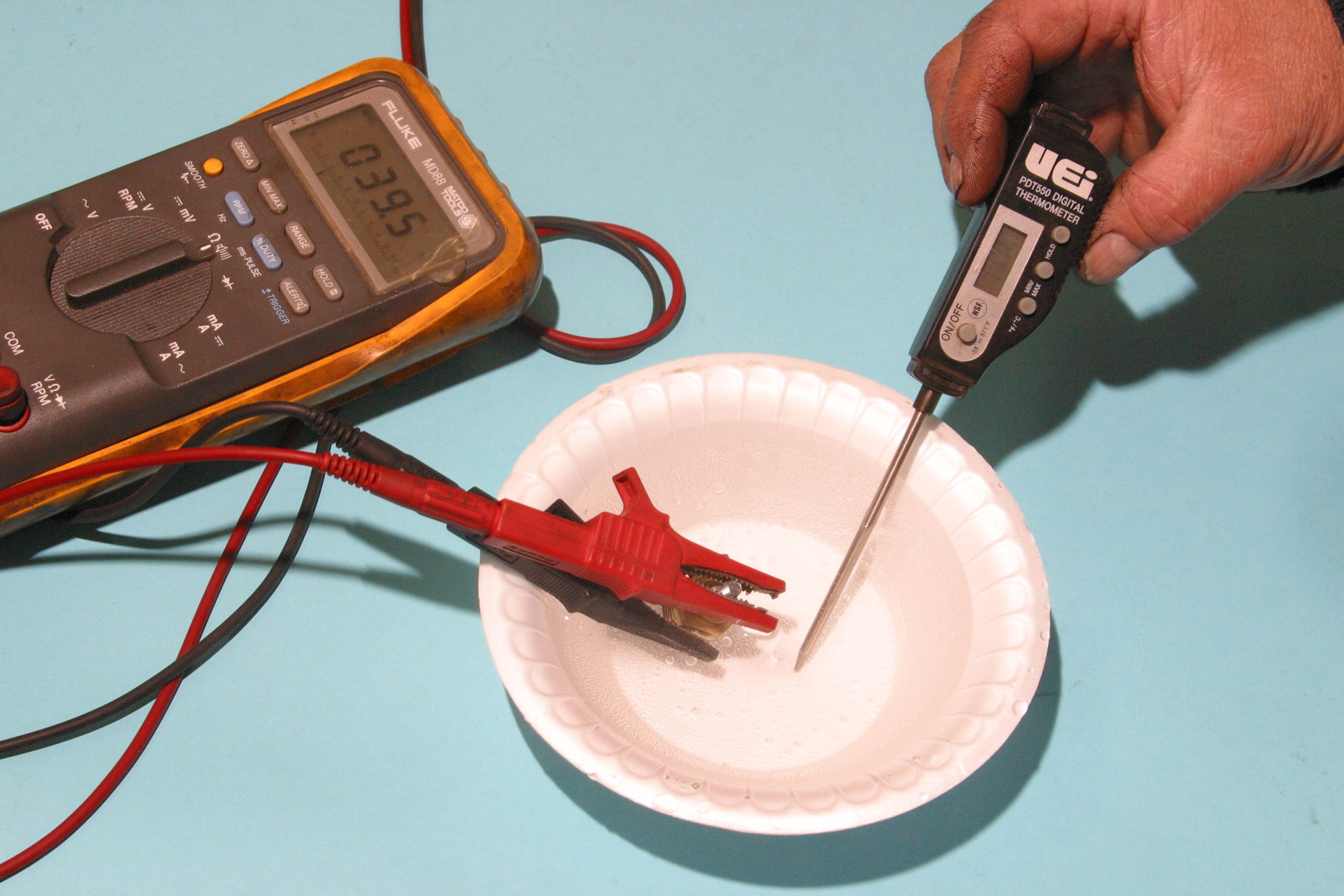
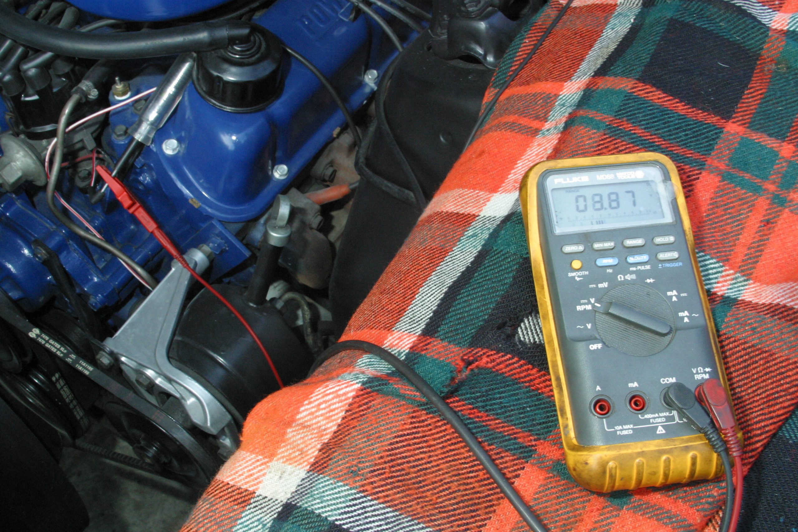
Whenever you’re troubleshooting the electrics, get yourself a multimeter. A voltmeter (multimeter) or a test light will tell you if there’s power and where. An ohmmeter will tell you how much resistance there is across a circuit or a sending unit.
What is An Idiot Light?
The “Idiot” light is a warning lamp that typically doesn’t illuminate until the problem has already arrived. The warning light gets your attention quicker than a gauge. Oil pressure lights illuminate at around five pounds of oil pressure in enough time for you to shut the engine down and get to the roadside.
Temperature lights come on around 220 to 230 degrees F, which is early enough to get to a stopping point for a cooldown. The “ALT” or “GEN” lights come on the minute the battery isn’t getting a charge, which gives you time to get to a stop.
Warning lights work the same way as gauges through a controlled grounding at the sending unit. Oil pressure and coolant temperature lights receive power from the ignition switch in the “on” position. They light whenever the completion to ground is accomplished. Instead of these senders being variable resistors, they’re an “on/off” switch to ground. During an engine overheat, the sending unit’s bimetallic contact closes the circuit and completes the path to ground. The oil pressure sender is a spring-loaded contact to ground. When there’s oil pressure, the sender is open with no current flow to ground. Lose oil pressure and the contacts close, yielding a path to ground, which illuminates the oil pressure light.
ALT and GEN lights show the battery isn’t getting a charge. Where the charge light differs from the ammeter is how it gets its power. When the battery is being charged (current flowing from the alternator/generator to the battery), there is no flow of electricity from the ignition switch via the voltage regulator to ground (light off).
When the battery is discharging, there is flow from the ignition switch to the voltage regulator to ground (light on). With a charge light, there is no doubt about charging system function. If the light is on, your charging system is in a state of discharge. If it is off, the system is charging, although it’s unknown to what degree. Aside from the possibility of a burned-out light bulb, the charge light is idiot-proof.
Tachometer Function
The tachometer functions based on input from the engine’s ignition system. The tachometer gets its power from the ignition switch (ignition on) and input from the negative (distributor) side of the ignition coil. Tachometers aren’t serviceable because they tend to be factory sealed.
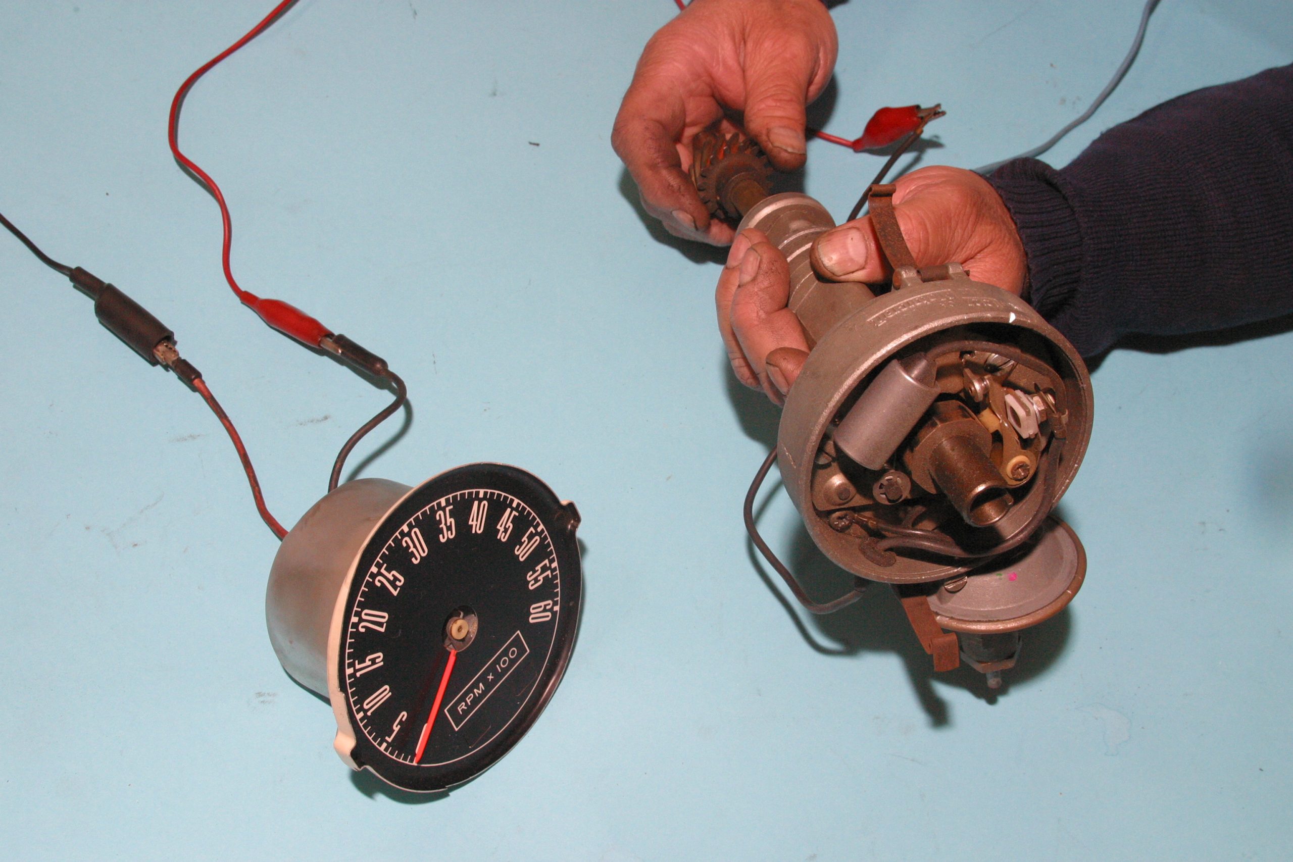
Tachometers stop working when there’s a disrupted connection between the ignition switch and the tachometer or between the ignition coil and tachometer. There are instrument shops online that can handle your tachometer including calibration.
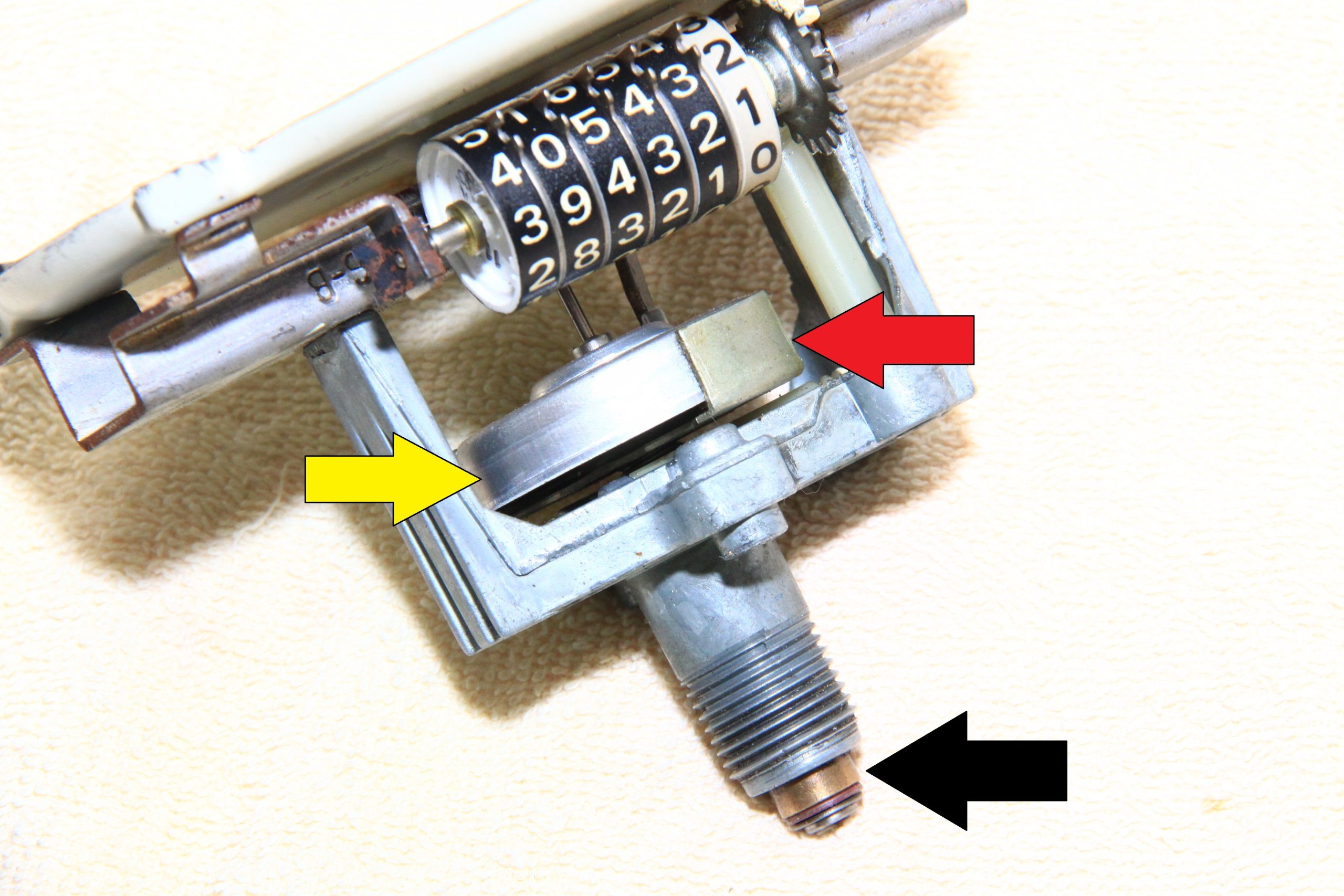
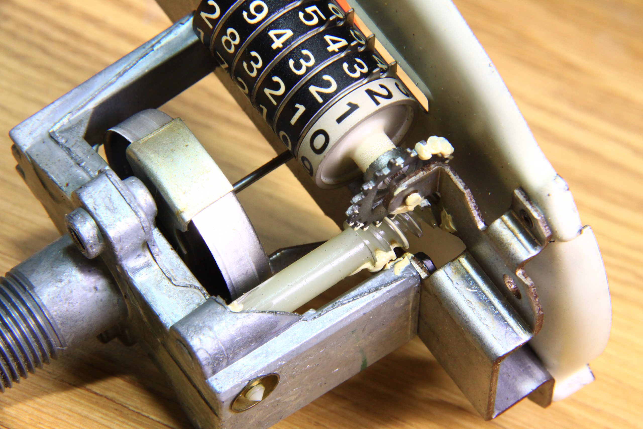
The Speedometer
Vintage mechanical speedometers are driven by a drive gear/driven gear package at the transmission and a driven cable connected to the transmission’s tail shaft. Splines on the transmission’s tail shaft drive a small nylon drive gear tied to the speedometer cable that drives the speedometer head via the cable. The speedometer head is a rotating magnet that spins around inside a hollow shell linked to the speedometer needle. The spinning magnet’s magnetic field attracts the shell that moves the needle. The faster the magnet spins, the higher the needle goes.
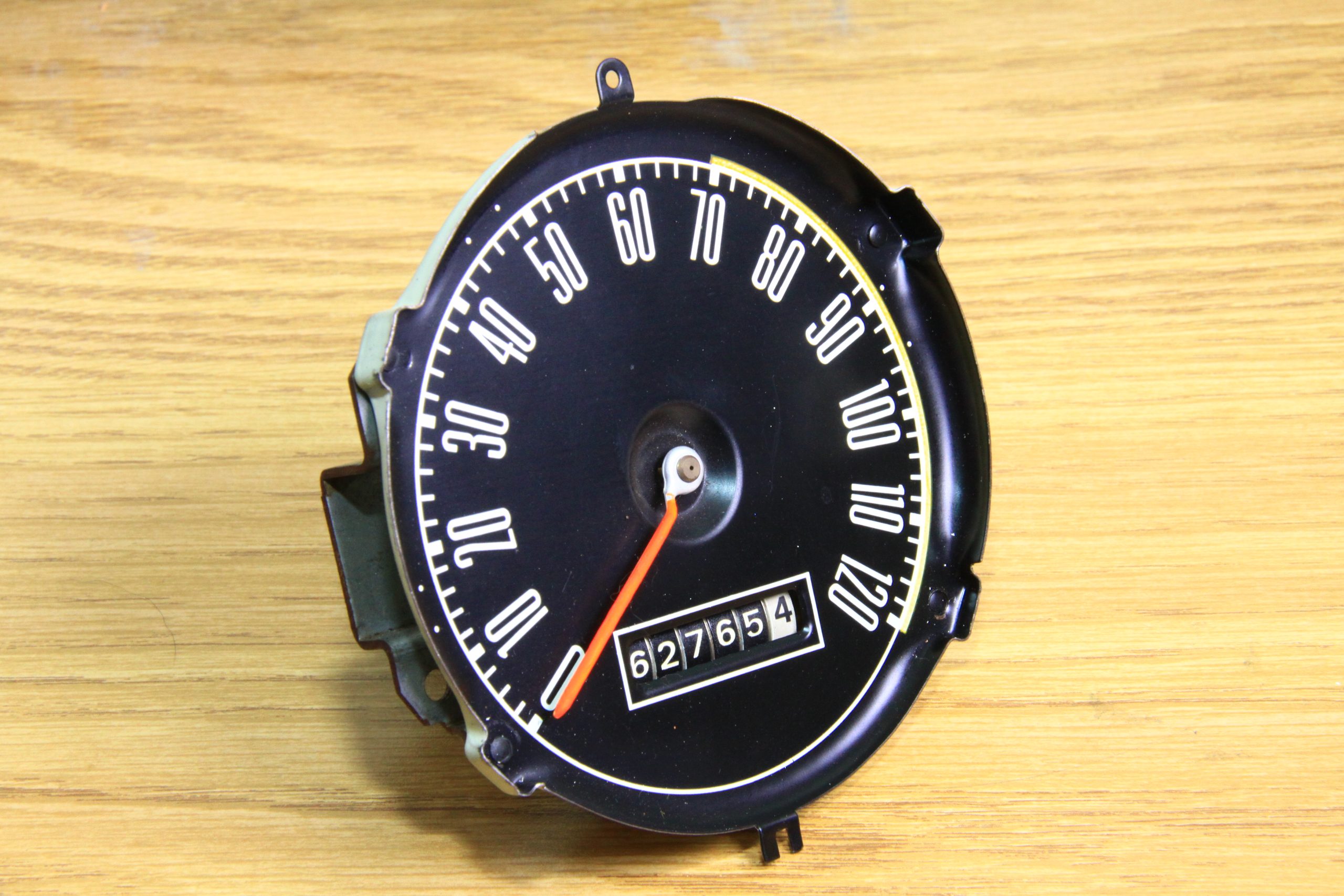
Speedometers fail when cables bind and break or magnetic heads cease due to the absence of lubrication. The spinning speedometer head requires occasional lubrication (speedometer-head lubricant). While you’re at it, pull the speedometer cable out and bathe it in white lithium grease.
Speedometer calibration is mostly a matter of using the correct drive gear at the transmission. There are also online and local shops that can calibrate your speedometer. Begin by taking the pace vehicle on an open highway where there are mile markers. Get the vehicle speed to a steady 60 mph and look at your watch. If the speedometer is accurate, it will take exactly 60 seconds (one minute) to travel one mile.
If your speedometer reads higher than your actual speed, you need a drive gear with more teeth. If your speedometer reads low, you need a drive gear with fewer teeth. A drive gear with 18 teeth is going to turn faster (and read faster) than a drive gear with 21 teeth as one example.
If your speedometer is reading 10 mph high and there’s an 18-tooth drive gear, you need a 20-tooth drive gear. The highest number of teeth available on a Ford speedometer drive gear, as one example, is 21. If you’re running racing cogs like 4.11:1 and beyond, run a reducer, which may be challenging to find.
Tire size also affects speedometer readout. Taller tires will make the speedometer read low. Shorter tires will make it read high. Even tire inflation will affect speedometer readout.
Excellent! Thank you.