It’s really easy to get into trouble when routing fuel lines in your car.
A couple of issues include keeping the line away from rotating parts (for example, a spinning wayward driveshaft or a potentially exploding clutch) and keeping the line away from the scrub line on a car.
The term scrub line sounds exotic, but figure it this way: Think of what would rub (scrub) on your car if it had a tire go flat or worse, if an entire wheel departs.
Bottom line here is, you really don’t want the fuel line to be part of that potential mess.
Another huge concern is heat. Engines produce a lot of heat. More by the exhaust system and even more by the headers. No secret.
Another point to consider is the need for servicing.
For example, the filter should be mounted in a spot where you can get at it.
When laying out a fuel system, it’s best to figure out where various components such as the fuel pump and filter(s) are mounted first.
In the example shown in the accompanying photos below, the car was set up for a high volume mechanical pump.
Fuel was set up to be regulated at the carburetor with a mechanical fuel injection bypass valve (not shown) and then returned to the tank. A single fuel filter was plumbed into the supply line.
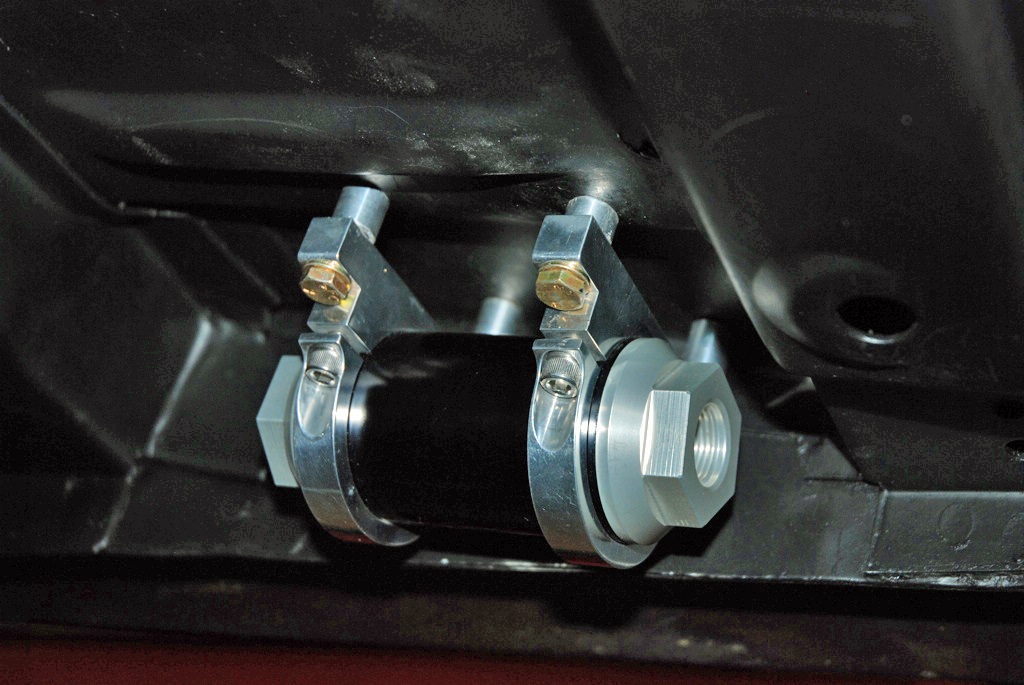
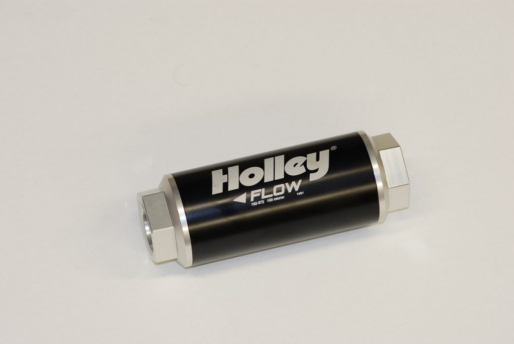
A high-capacity Holley HP billet inline fuel filter was mounted under the passenger seat area.
This is curbside of the front subframe and also curbside of the frame connector which keeps the filter away from the exhaust system and away from any potential driveline carnage.
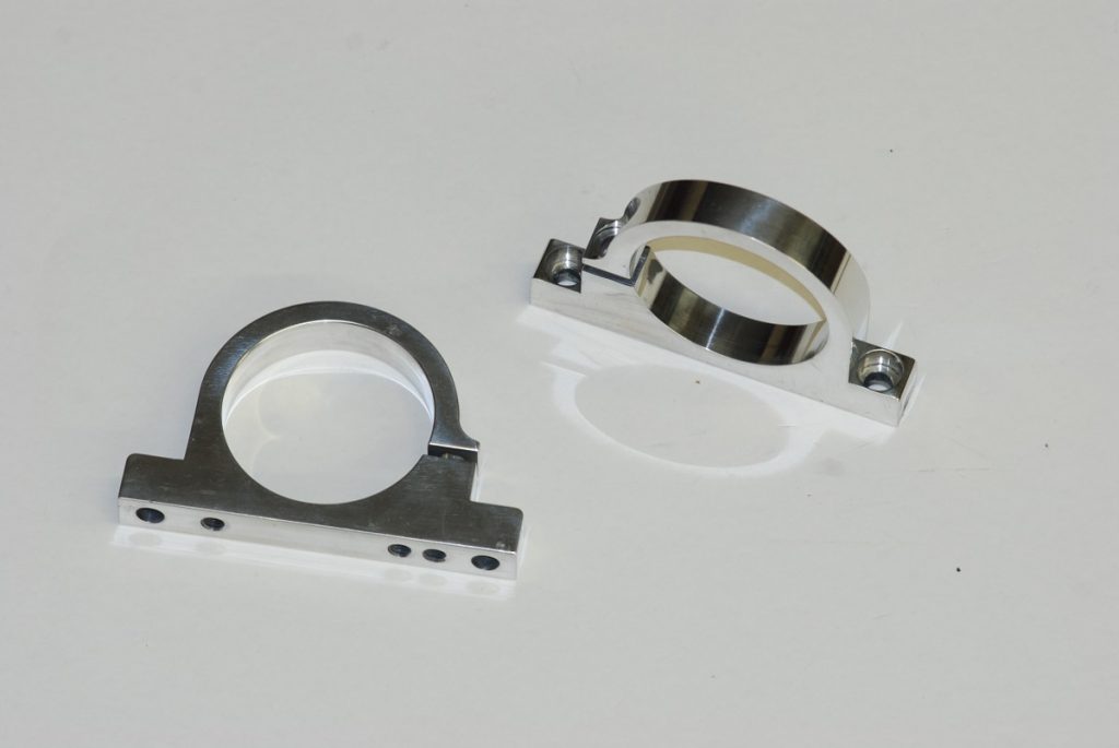
A set of Holley billet filter mounting brackets were incorporated but there was a hitch: Mounting the filter wasn’t exactly painless due to the irregular shape of the floor pan.
The fix here (and one you might want to copy) is to craft four spacers to locate the filter so that it’s level and accessible.
Fabricating spacers might sound difficult, but it certainly isn’t a big deal. We simply used sections of ½-inch OD aluminum tubing for the job. It took various heights of spacers and different length bolts to level the filter, but once done, this arrangement allows for easy access to either end of the filter.
Next up, we moved to the front of the car. We needed to run a feed line from the filter to somewhere near the engine (in our case, near the mechanical fuel pump). We also needed to fabricate a return line. Our feed line is -10AN while the return line (that eventually routes to the bypass valve) is -8AN.
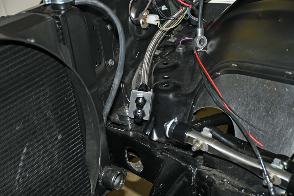
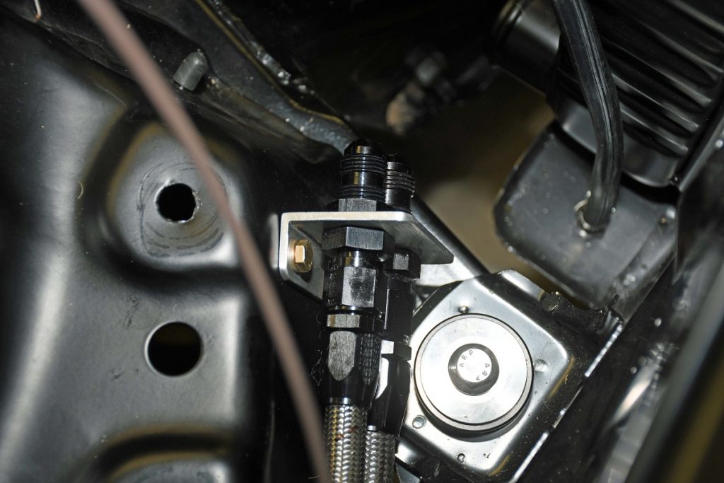
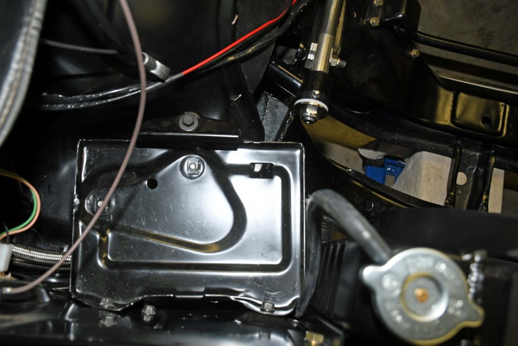
We fabricated a simple L-shaped aluminum bulkhead plate to mount the feed and return lines more or less hidden underneath the OEM battery tray.
We’re using a -10AN feed line that will then go to a billet Holley mechanical fuel pump (we don’t have the engine in the car so we can’t finish that part of the plumbing). After the fuel goes to the carb, it returns to the bypass valve, which hooks up to the -8 bulkhead return line fitting under the battery tray (again, this isn’t complete because there is no engine in the car).
Fair enough, but this is where the routing differs from the norm.
The OEM fuel line runs on the inside of the frame rail at this point. That means it is positioned adjacent to passenger-side header. Obviously, that tends to bake the fuel.
In the past, we’ve had modified cars that actually boiled the fuel due to the line location. The result is vapor lock.
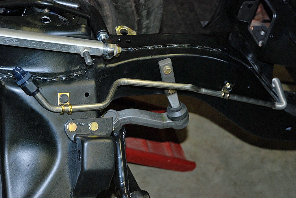
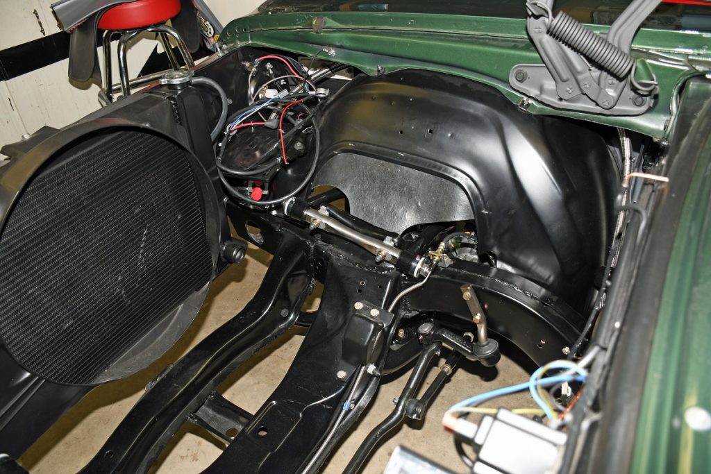
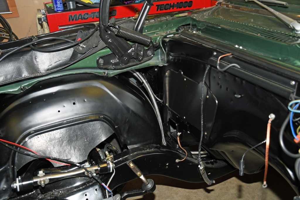
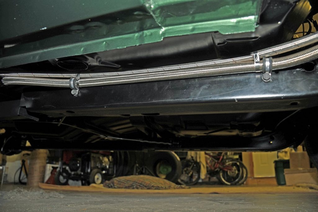
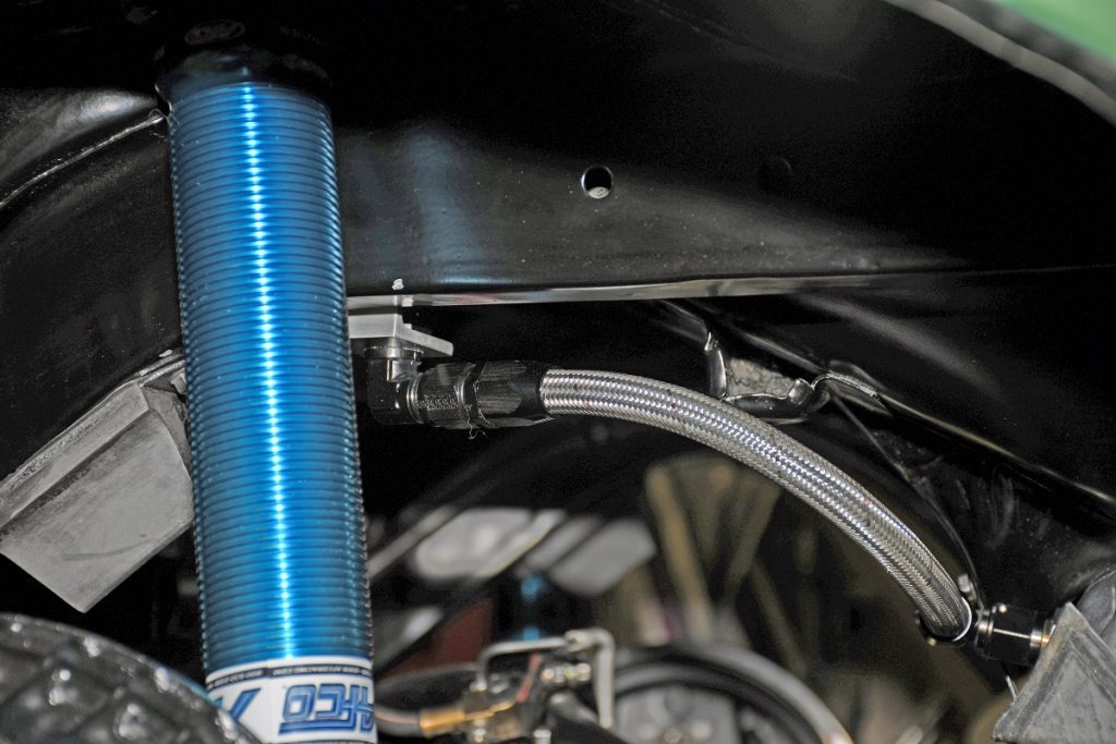
In our case (and something we’ve done regularly in the past), the pair of lines were routed over the top of the passenger side inner fender and then down along the curbside of the frame rail and frame connector.
This setup also serves to keep the fuel line away from the drivetrain of the car (in particular, the bellhousing).
Down below, the lines were also mounted as high as possible in order to keep them away from any potential scrub line interference. Eventually, the feed line hooks up to the fuel filter.
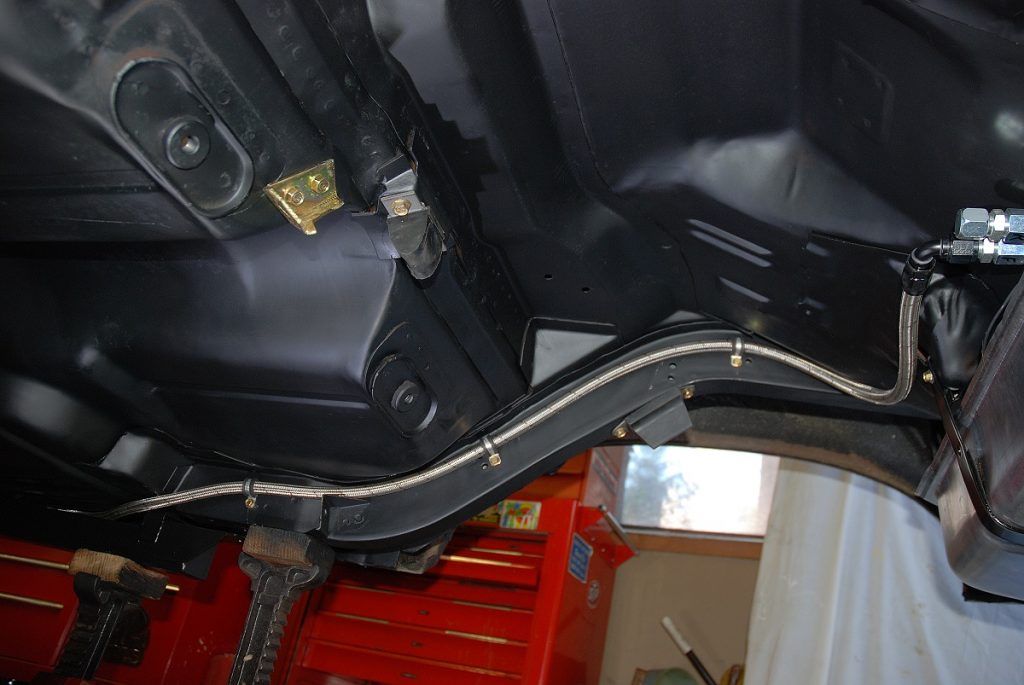
Both the fuel feed and return lines follow the frame connector, then loop over the top of the passenger-side frame connector to join the inner side of the rear subframe.
This keeps the fuel lines away from the wheel and tire on the passenger side and it also keeps them well protected by the rear frame rail and frame connector.
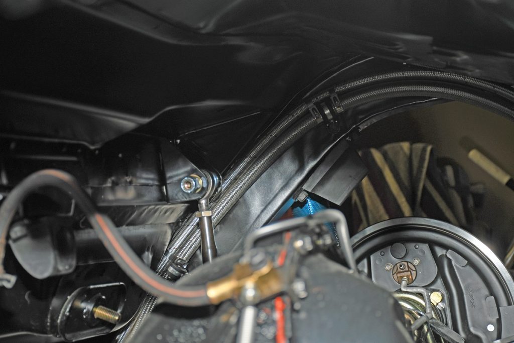
Finally, pressure and return lines hook up to the bulkhead fittings at the leading edge of the gas tank. The vent line runs up from the top of the tank to a fabricated bracket on the inside of the driver’s side rear subframe.
There, a bulkhead fitting hooks to a simple billet breather. The idea here is to keep the vent line (breather) as high as possible in the chassis.
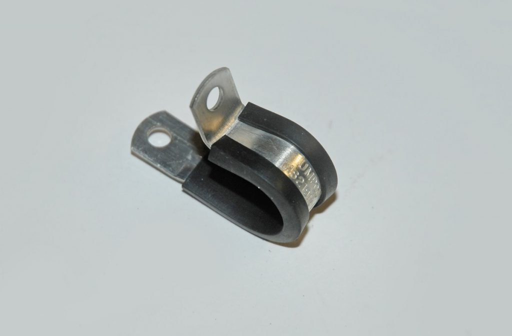
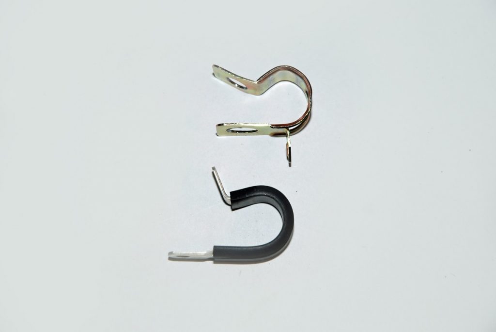
The obviously need to be secured.
In our case, we used a mix of Earl’s cushioned clamps (or “Adel” Clamps) along with stainless steel tie wraps (thermal locking ties) to secure the lines.
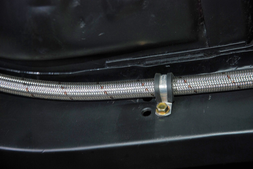
Stainless steel locking ties can be cut to size, just like zip ties. In order to keep everything tight, the big -10 line was clamped at regular intervals while the -8 return line was tied directly to the -10 hose. By “regular intervals”, we simply mean we measured the space between the clamps, mounted them in the same orientation where possible, and kept them all in the same height in relation to the bottom of the subframe. This kept the line tight and it makes the whole thing neat and tidy.
In the end, this system keeps the fuel line out of harm’s way. Additionally, it keeps the fuel from getting heat soaked. It’s easy to service, and it’s equally easy for you to duplicate.
For a closer look, check out the accompanying photos:
[…] It’s really easy to get into trouble when routing fuel lines in your car. A couple of issues include keeping the line away from rotating parts (for example, a spinning […] Read full article at http://www.onallcylinders.com […]
Been trying to route the fuel lines on a Plymouth Slant-6 with a Holley 390 4150 series. I was wondering how close is too close to manifold heat? I was planning on using DEI gold wrap with the heat tape regardless but the 4150 line seems to be a little close for comfort. Any ideas?
It is the lead in the old style fuel that was the killer,When you worked in the sparks electrical shop making batteries we had to go to hospital every three months for lead poisoning tests ,For cleaning parts we used unleaded petrol… https://wikipagemaker.com/
Very good ideas, I liked
I am building a FI injected hot rod with a vented S/S tank. I have a roll-over valve that should connect to a vent/breather, but I haven’t been able to find a good choice. Can you tell me what part (manufacturer and part number) you used for your tank breather?
This is really helpful, I appreciate it.
it looks like you were routing the fuel lines from around inter fenderwell to the out side of a 70 chevelle frame. then running it on curb side of frameto the back . My question is where did you cross at the back ,back to inside of frame to go to fuel tank or cell in my case?? could you advise me as that is what iam going to do on my chevelle
Hey Gary, Wayne’s car here is an x-body Nova. But you can see where he brings the fuel lines inboard here in this pic, it’s right ahead of the rear wheel arch. Thanks for reading, hope this helps.