The designers of late model engines like the GM LS, Ford Modular engine, and the Chrysler Gen III Hemi have in many ways made it easy for performance enthusiasts.
Not the least of which is the net lash system where the engine builder doesn’t have to run through setting hydraulic lifter preload on all 16 valves.
In a net lash system, a set distance between the lifter (on the cam lobe’s base circle) and the rocker arm creates the preload on the lifter based on pushrod length. To set the preload, all that’s necessary is to torque the bolts down on the rocker arm. It’s that simple.
This is not the case with older engines like small- and big-block Chevys and Fords. These engines and many others require adjusting either the preload on the hydraulic lifter, or setting mechanical cam lash (clearance) for each individual valve.
In prehistoric times, tuners set lash or preload with the valve cover removed and the engine running — creating an oil-flinging mess. There’s a much cleaner, more efficient way to accomplish this with the engine not running.
Let’s start by reviewing why lash is needed on mechanical cams and preload is necessary for hydraulic lifters.
Mechanical camshafts, both flat tappet and rollers, require clearance between the cam lobe and the follower. Older camshafts were designed with much wider clearances than modern camshafts. For example, the original 302 c.i.d. Z-28 engines used a mechanical flat tappet camshaft that required 0.030-inch of clearance when the engine was hot. Current performance mechanical rollers have reduced that figure to as little as 0.010- to 0.12-inch.
Hydraulic lifters operate differently. These employ a small piston inside the lifter body supported by a short column of oil. The lifter is designed to be preloaded or compressed for a given amount. This creates a short column of pressurized oil underneath the piston that automatically compensates for expansion as the engine reaches operating temperature. This column of oil maintains the proper valve opening and closing relationship throughout the entire engine temperature operating range. That is not the case with mechanical camshafts where the lash will change when the engine is cold compared to at normal operating temperature.
There are actually several procedures for adjusting lash with the engine not running, but we’ll show you the one that is easiest to remember.
This process does not require you to memorize the engine’s firing order. The originator of this idea is lost to history, but he was probably a cam designer or a racer who was interested in a simple process that’s easy to execute.
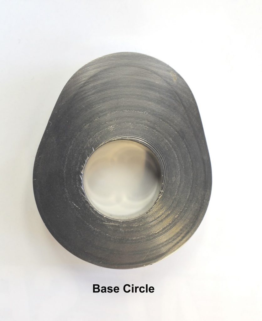
The important part of setting lash or preload is to ensure the lifter you will be working with is on the base circle of the lobe. This is very important. We’ll use a big-block Chevy for this demonstration. While we’re using this particular engine, this process can be used on any four-stroke internal combustion engine because they all operate the same way.
We call this process Exhaust Opening-Intake Closing (EO-IC). If you turn the engine over slowly clockwise, watch the valves as they operate. When the exhaust valve begins to open, this places the intake lifter on the same cylinder on the base circle of the intake lobe. This allows you to set the lash or preload on the intake lobe.
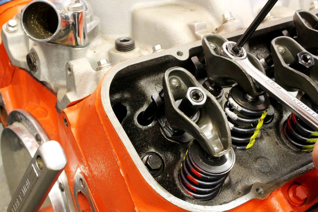
Then if you turn the engine roughly 1½ revolutions, the intake valve will begin its lift cycle. When the intake rocker is more than halfway down the closing side, this will place the exhaust valve on its base circle so that it can be set.
If you’re not sure of the intake or exhaust valve, a simple way to do that is to line up the exhaust port with its valve. This is sometimes easier than tracing the intake port. If you find the exhaust valve, the other valve with be the intake.
We’ll run through one cylinder on our big-block to show how this works.
With the engine not running and the valve covers off, we like to start with the Number One cylinder which is, in this case, the leading cylinder on the driver side. If the engine is in the car, you can bump the engine over with the starter motor. Of course, you can also turn the engine over using the crank bolt.
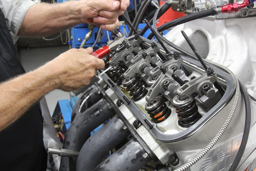
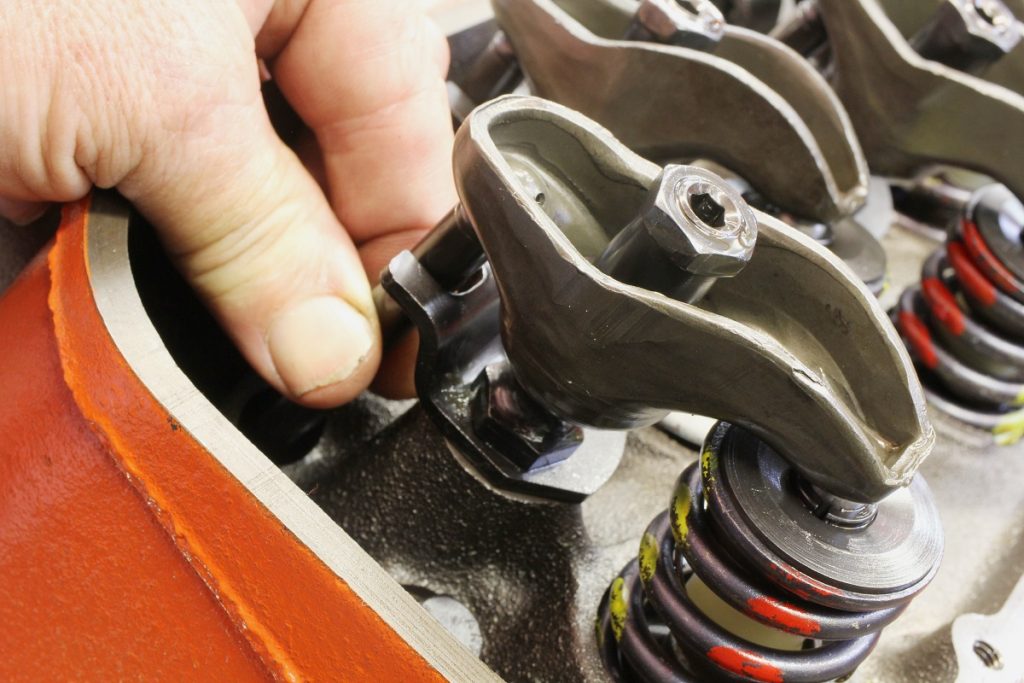
The procedure starts by turning the engine and watching for the exhaust valve to open. Once the exhaust valve begins to open (EO), we can now move over to set the preload on the intake valve for that cylinder. Our particular big-block is running a hydraulic flat tappet camshaft, so we will want to set roughly a half-turn of preload into the lifter.
Let’s assume we’re setting the preload for the first time. With the rocker arm loose, tighten the adjuster on the rocker stud while feeling clearance with the rocker arm and there’s no tension on the pushrod. You can also twirl or spin the pushrod with your fingers on your left hand as you tighten the rocker stud adjuster with your right. If this is a brand new engine, we like to perform this lash adjustment before we install the intake manifold so we can watch the cup in the lifter to see exactly when zero lash is achieved. If the engine is fully assembled, pay close attention to when pushrod clearance is eliminated. This is zero lash.
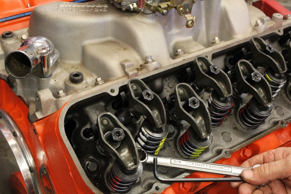
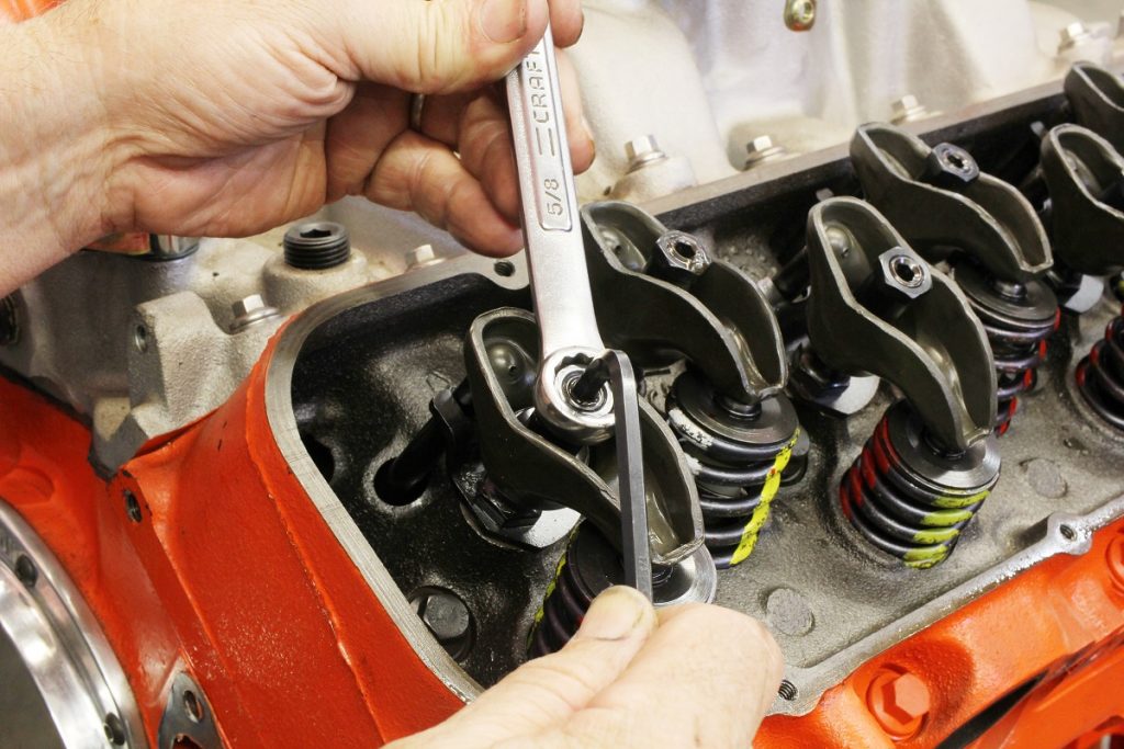
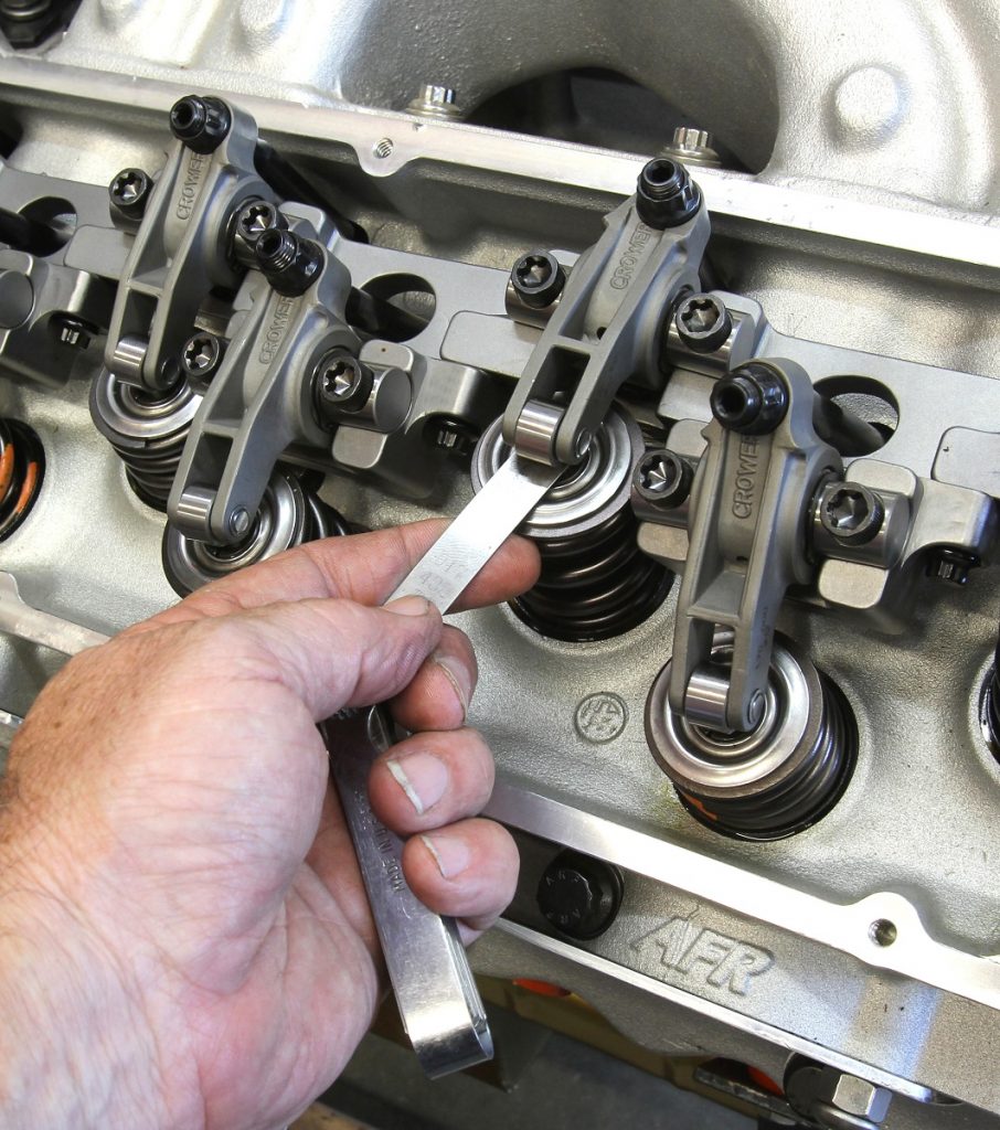
To set preload, merely tighten the adjuster nut another half-turn after zero lash. If you are setting the lash on a mechanical lifter camshaft, use the appropriate feeler gauge between the valve tip and the rocker arm and adjust the lash until there is a reasonable tug or pull on the feeler gauge. With both the intake and exhaust valves set on this cylinder, we can move down the line to each adjacent cylinder. I prefer to do one cylinder at a time in sequence. This minimizes mistakes from overlooking a pair of valves.
One variable is the question of the amount of preload. For decades, older engines required a preload of three-quarters to one full turn of the adjuster. Later, the performance industry evolved to a reduced setting of quarter-turn. If we read the COMP instruction however, they recommend a three-quarter or one full turn much like the OE’s.
One way to determine the actual amount of preload is by the thread count on the rocker stud. For example a 7/16-inch rocker stud uses a fine thread which is 20 threads per inch. This means one full turn on the adjuster nut is worth 0.050-inch. Once zero lash is determined, a half-turn of the adjuster nut will depress the lifter piston 0.025-inch. A full turn will produce 0.050-inch.
It’s beyond the scope of this story to dive into a full investigation into hydraulic lifter preload here. Let’s just say that one full turn of preload generally tends to improve performance on hydraulic lifter engines. The reason for this is that the greater preload pushes the internal piston closer to the bottom of its travel. This reduces the volume of oil underneath the piston.
This minimizes the amount of air entrained in the oil that will allow the piston to compress.
Remember, a liquid cannot be compressed while air is easily squeezed. By reducing the volume under the lifter piston, this creates a situation where the lifter acts more like a solid lifter — which is a good thing. Of course, this assumes that the valvetrain will remain stable at high rpm and not experience valve float.
If valvetrain separation occurs (due to loss of control or valve float), the lifter piston will instantly push upward, hold the valve open and the engine loses big power. So lifter preload is a double-edged sword. With this short explanation, at least you understand all the related factors.
By following this simple procedure to setting valves on an independent rocker stud style engine, you can now quickly set the valves without having to look up reference materials, setting sequences, or memorize a firing order.
Just remember Exhaust Open – Intake Closing – EO – IC and you’re halfway to completing the project.
[…] The designers of late model engines like the GM LS, Ford Modular engine, and the Chrysler Gen III Hemi have in many ways made it easy for performance enthusiasts. Not […] Read full article at http://www.onallcylinders.com […]
The reason behind the firing order system is for example an in line 6
If you rotare the crank until ypu have no 1 rocking you can now ajust bothe inlet & exhausr valve lash on no 6
Then the next in the firing order is 5 so a short ratation will bring 5 rocking and you would ajust 2 a short ratate will bring 3 rocking ajust 4 , and so on this saves time as you are ajusting both inlet & exhaust and it is easier to keep track of were you are
I have a 1987 Ford Mustang 302 5lt Cobra motor and see only hold down bolts in the center of the valve rocker arms ., hydraulic lifters , roller cam. NO VALVE ADJUSTMENT???? Do l just torque these bolts to 15 lbs ???
Paul,
Yes your engine is designed to be what is called a net lash system. I should have taken a sentance or two to explain this. The hydraulic preload is pre-set with the length of the pushrod, so yes you jsut torque the bolts to the required setting and the preload is already set. If you wanted to preload the lifters slightly more or less this would have to be accomplished by lenthening or shortening the pushrod length. But in your case the stock length is fine.
I want to no how to set all generator valve cat $ Perkins
[…] a simple process. If you need help with this, you can refer to a story we’ve written for the Summit Racing Basics Series here. Our process is very simple and only requires that you remember the initial EO-IC, which stands for […]
[…] (Image/Jim Smart) Engine builder Jeff Latimer has presented us with the best approach. Do valve lash adjustment one bank at a time—hand-crank the engine in its normal direction. Watch the exhaust valve on the […]