Ford’s 4.6 3V, typically just referred to as a “3V” in the Mustang community, is a bit of an oddball in the modular engine family and definitely has its pros and cons. On the upside, they sound great and the extra valve and variable cam timing provided by the phasers on the camshafts provided more usable torque and horsepower in a street friendly range then the 2V it replaced. On the downside, it also introduced more complexity into the system while falling well short of the benefits that a DOHC 4V design would have provided.
For the most part, though, 3Vs are tough and reliable engines (provided that you keep the power under around 450 to the wheels), but there are a few issues that are going to pop up eventually. The most dreaded ones revolve around the timing assembly. The cam phasers can go out (usually a ticking sound gives this away), which isn’t a terribly hard swap since it can be accomplished by just pulling the valve covers. However, everything else timing related—including the infamous chain tensioners—requires significantly more time to resolve.
In the case of our project—burdened by 116,000 miles of SoCal traffic mixed with lots of autocross and track days—we had a few things going on. We knew the chain tensioners were failing thanks to a chain rattle upon start up. The cam phasers were ticking on both sides. And we knew something was going on with the chain guides when the chain’s movement suddenly became more audible one morning. When you hear any of these, don’t ignore them for long—they’ll definitely get worse quickly.
That’s when we parked it and decided it was time to take the plunge.
The somewhat good news when it comes to changing the timing assembly on a 3V is that it really isn’t that difficult of a job, technically speaking. If you can follow instructions closely, you can do this and save a bunch of money. The bad news is that it is really time consuming, which is why it tends to cost quite a bit at shops that tend to bill by the hour. We’ll be honest; we didn’t want to do it ourselves. However, even working with an experienced shop you’re looking at a minimum of 8 hours labor, and here in SoCal, that’s at least $900 at most shops, parts not included. Most quoted us around $1,200-$1,500.
Fortunately, since these are known issues, upgraded versions of all of the parts are readily available through Ford Racing Performance Parts, and are in stock at Summit Racing for the best prices. You can find off-brand/unknown brand kits available through other outlets online, but we strongly suggest only using Ford parts for this swap since the quality of other sources has been very suspect, and this is not a job you want to do more than once.
There are tutorials on YouTube that show full valvetrain disassembly and cam removal to do this timing upgrade, and while that’s fine, we’re going to show you the quickest and easiest way to knock this out. While those experienced shops may take 8-9 hours, we suggested budgeting a weekend for this job if you’re not a Ford tech.
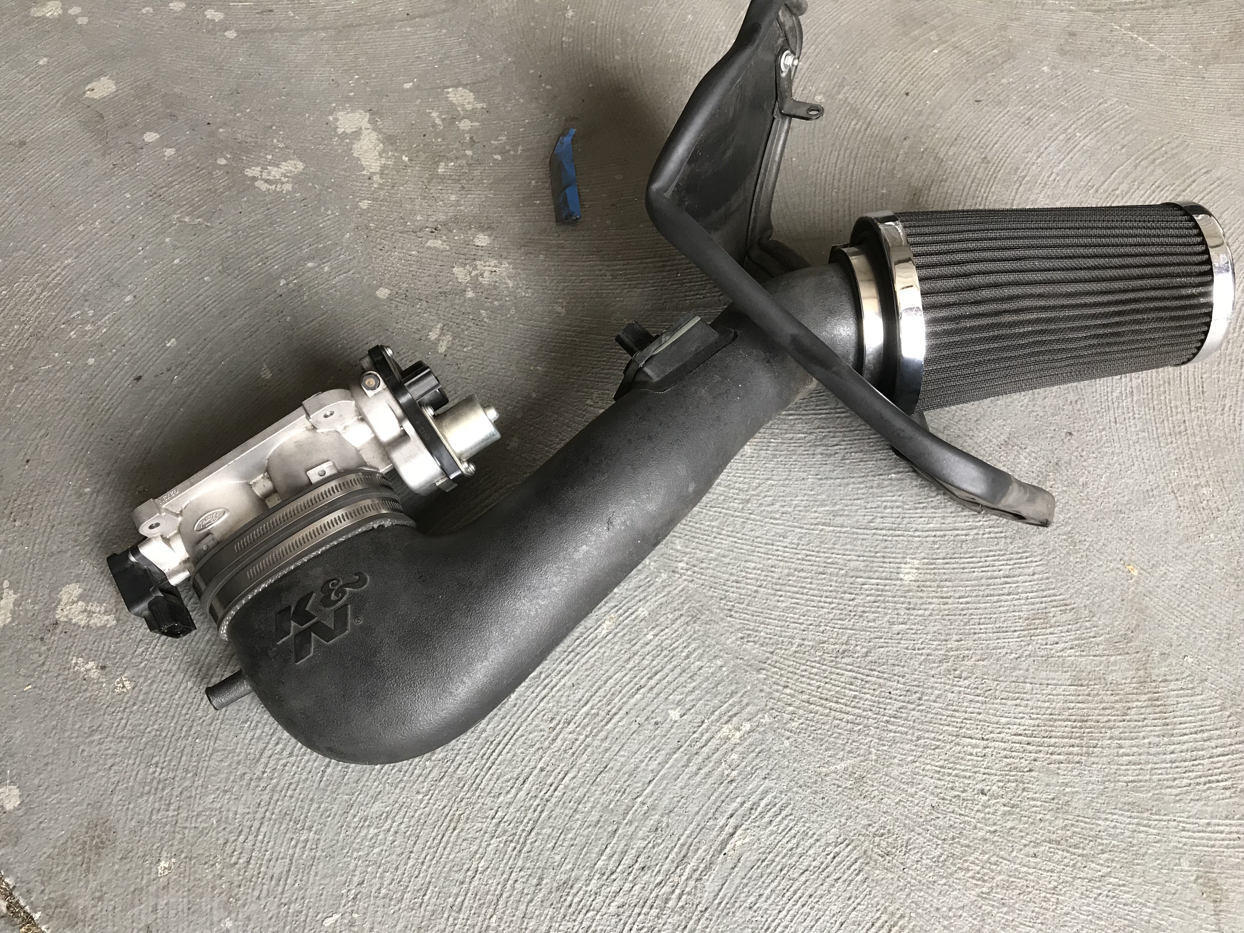
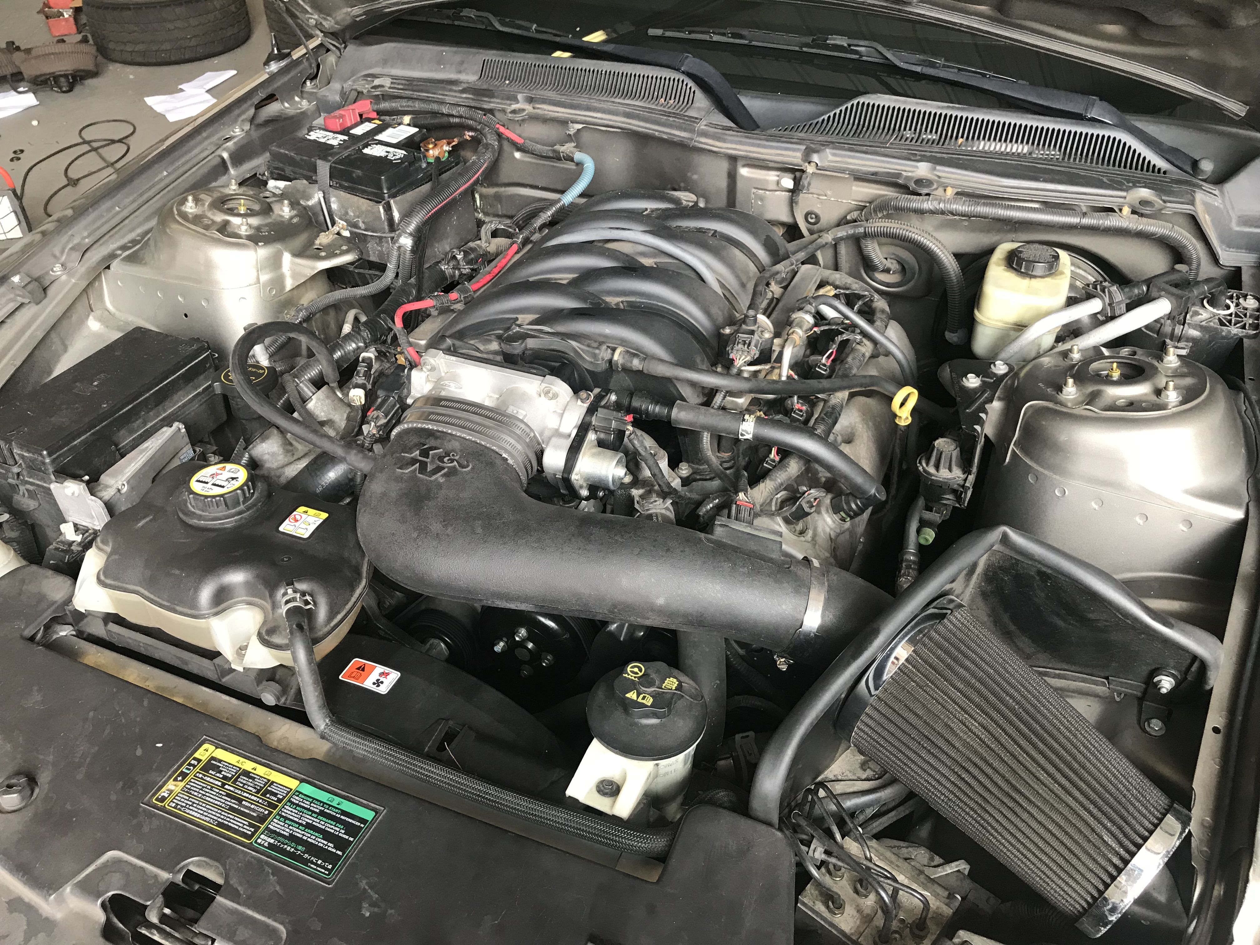
Our GT had a K&N cold air induction, so this first step is a bit different if you have the stock box, but not dramatically so. Once you remove the stock filter element, you should see the screws holding the box to the inner fender. With those loose, remove the two connectors on the throttle body and the 4 nuts securing it to the intake manifold and the whole assembly will come out as a single unit.
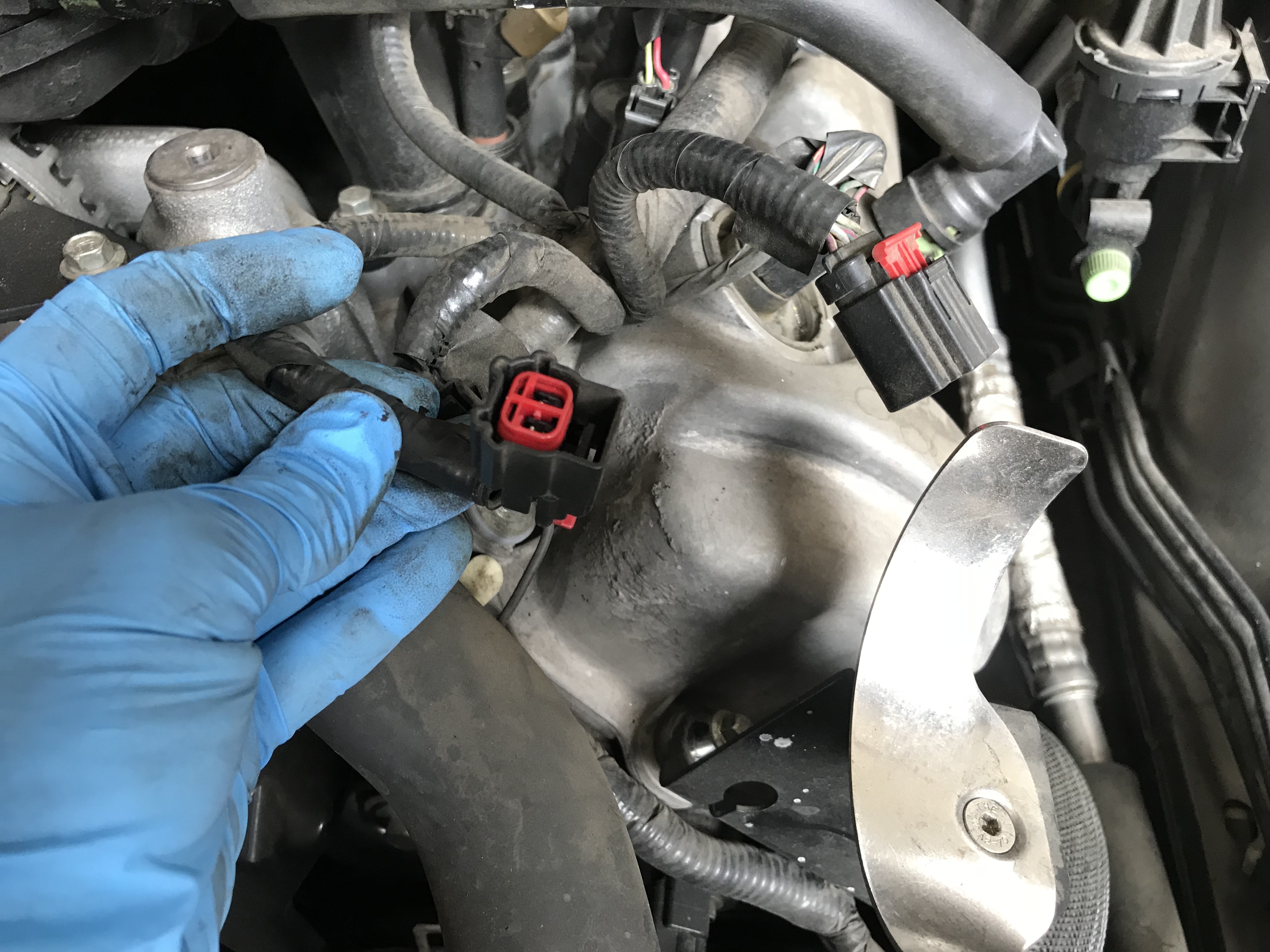
Speaking of connectors, the majority on the 3V engine looking like these two. Slide the red lock back to release the lever on the black part of the plug. Both of these parts can break pretty easily, so make sure each locking portion is disengaged before you pull. If you do manage to mangle one, don’t fret; NAPA carries generic replacements cheaply.
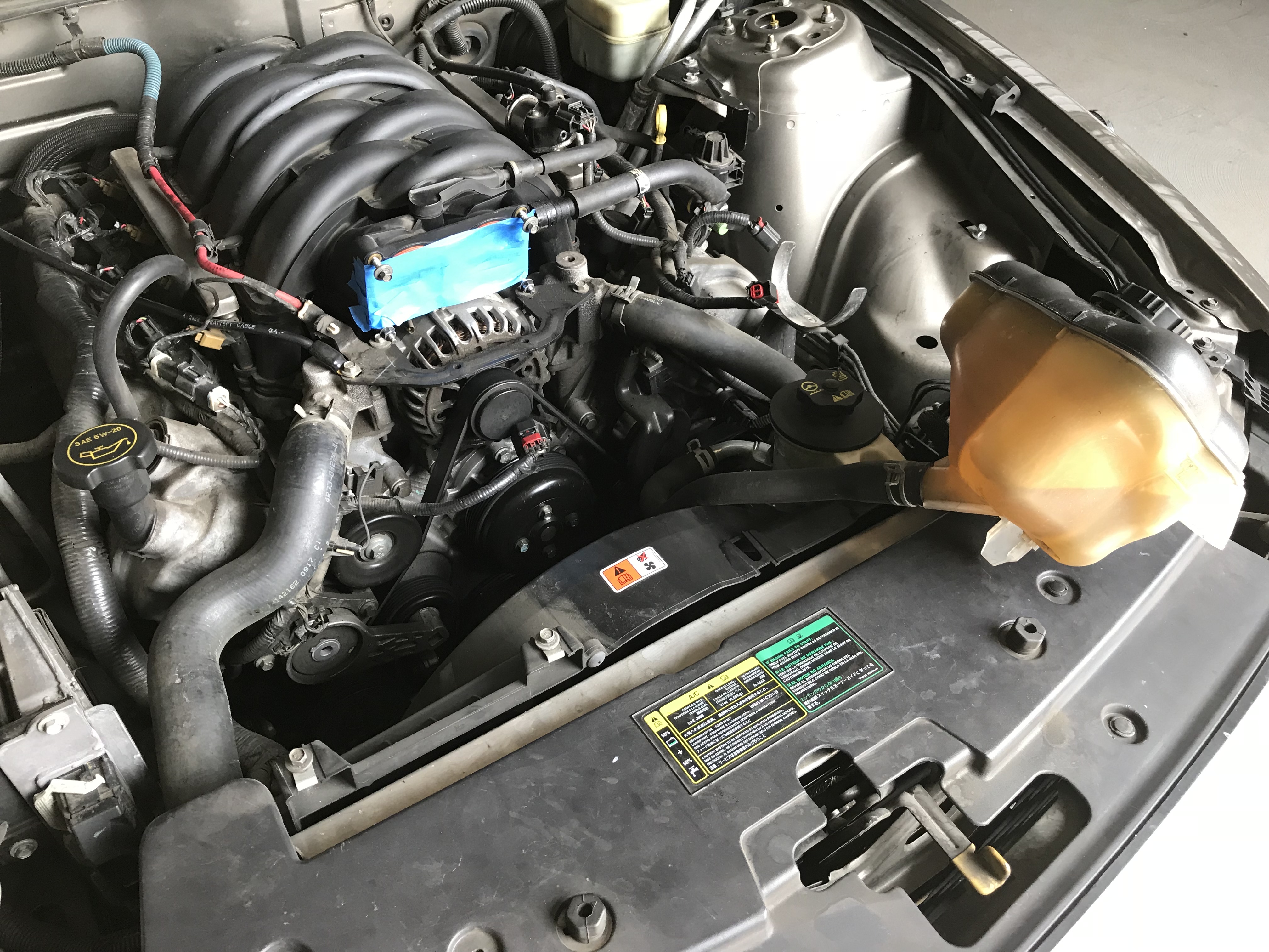
While most 3V timing chain tutorials will tell you to pull the radiator and fan assembly (or at least the fans), we prefer to disassemble only what is needed, so ours will be staying put, fluid and all. After removing 2 10mm bolts, you can shift the coolant reservoir over above the ABS module. Also, it’s a good idea to tape off the intake manifold or stuff a rag in it.
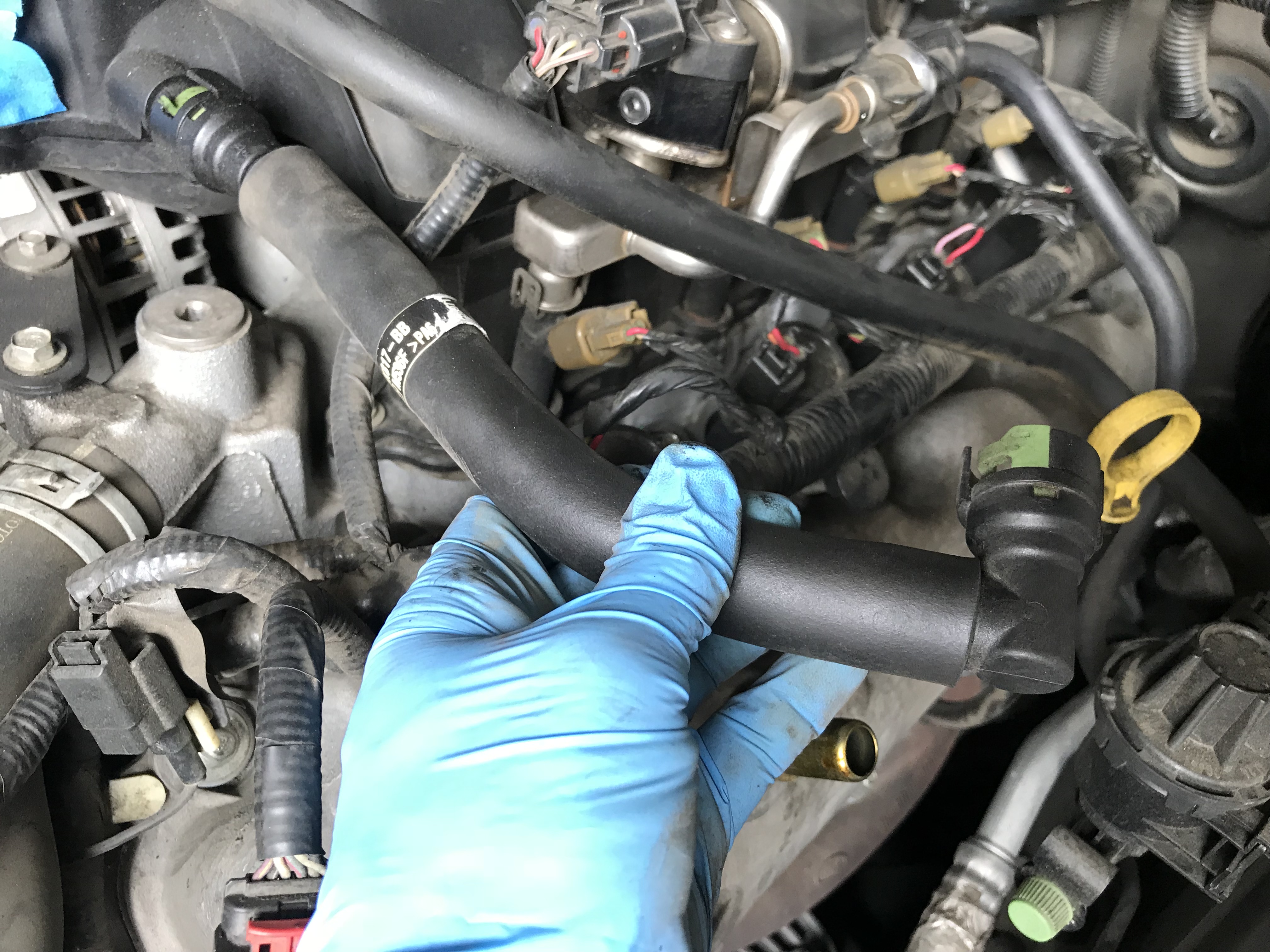
Before we get to the front cover, the valve covers need to come off. Unfortunately, that means we need to pull a bunch of things out of the way, including the PCV hose.
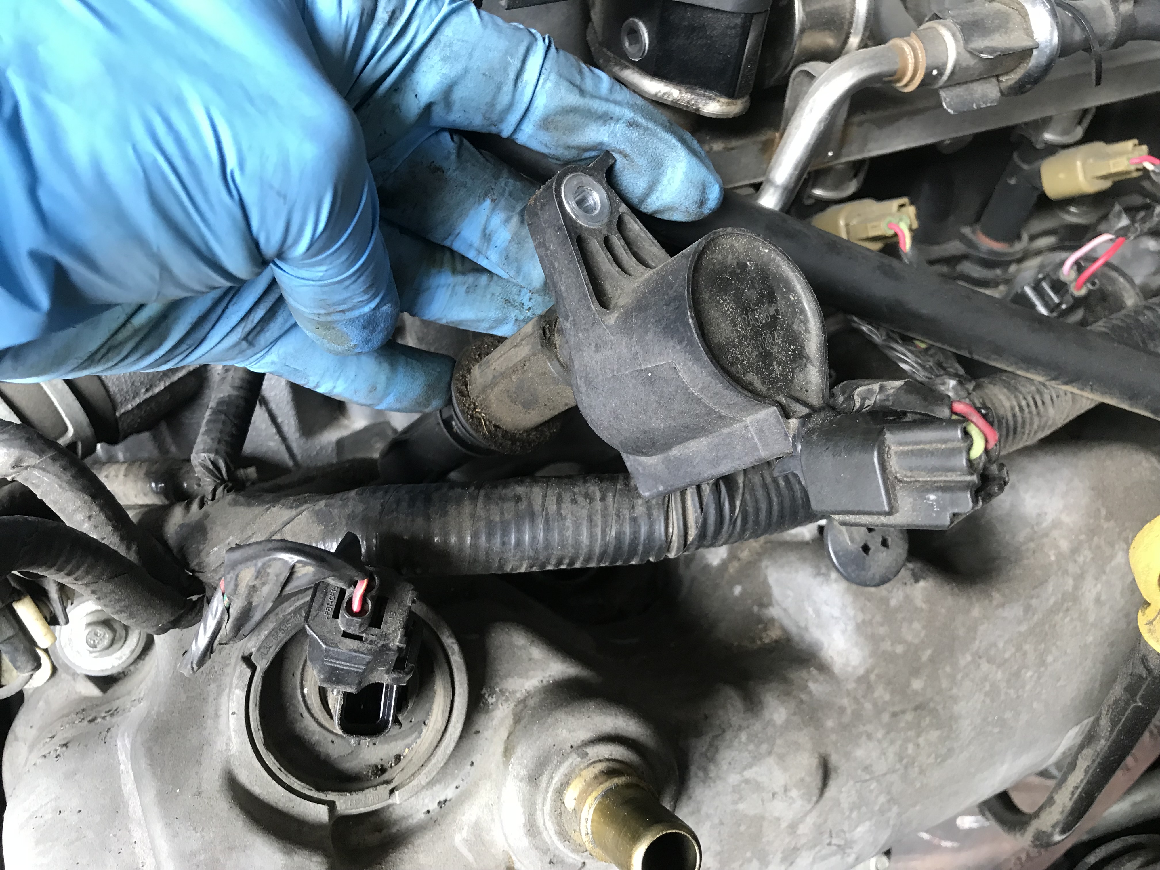
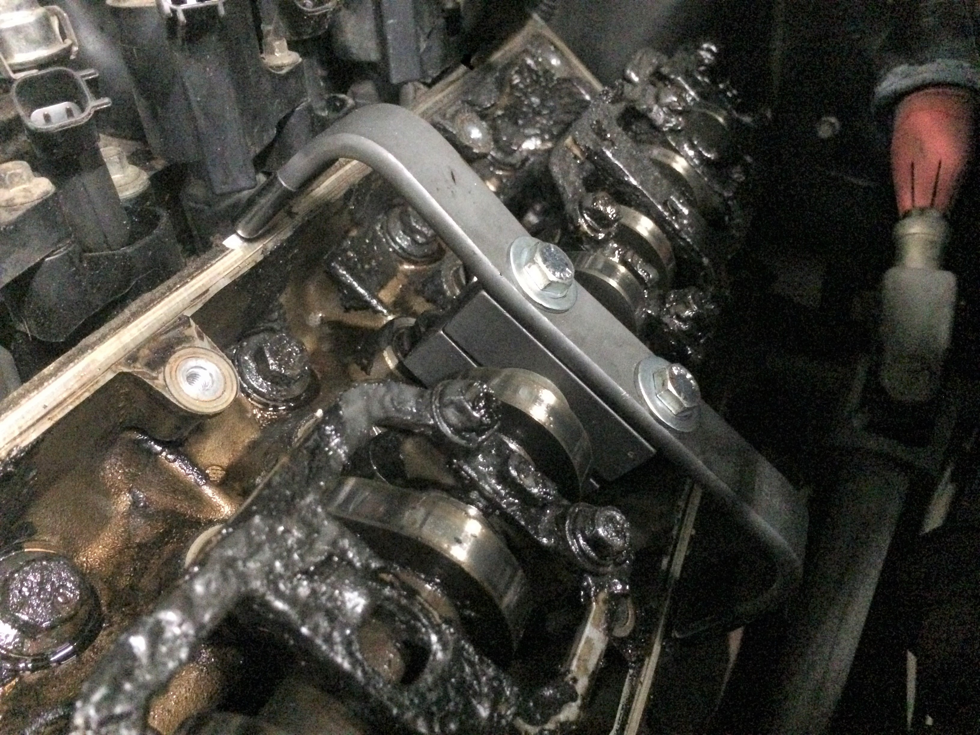
Next are the coil on plugs (COP). One 7mm headed bolt holds them in place. To clear room for the cover to slide out, pull the connector on the fuel injectors as well (the tan plugs in the pic) and VCT solenoids (black clip in the foreground). This will allow the whole harness to slide off the studs on the valve covers and shift up onto the intake manifold.
Good news and bad news about the valve cover bolts. Good news, the bolts are captured in the cover by inserts and won’t easily fall out. The bad news is that there are lot of them and the ones in the back are a little tough to get to.
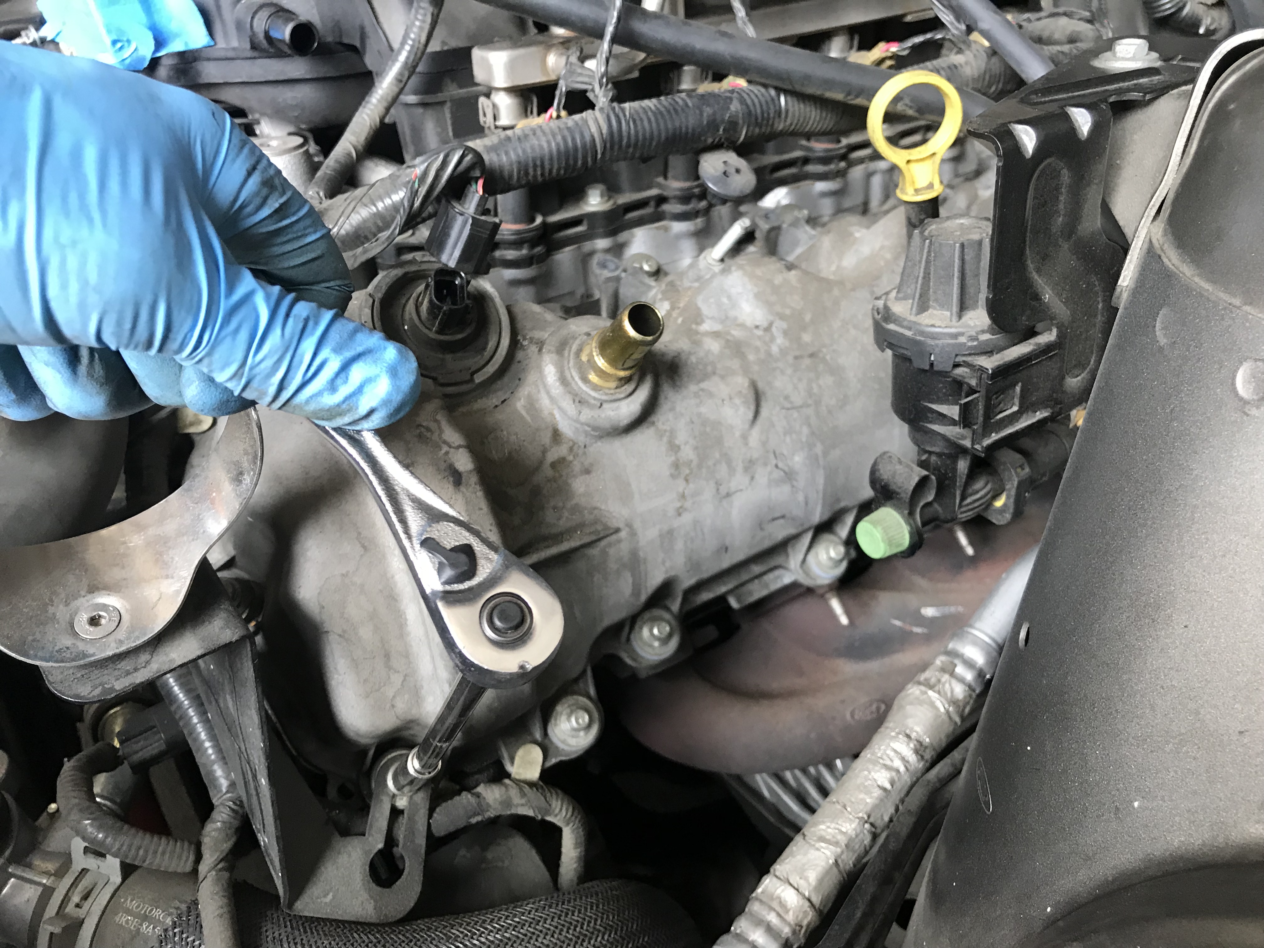
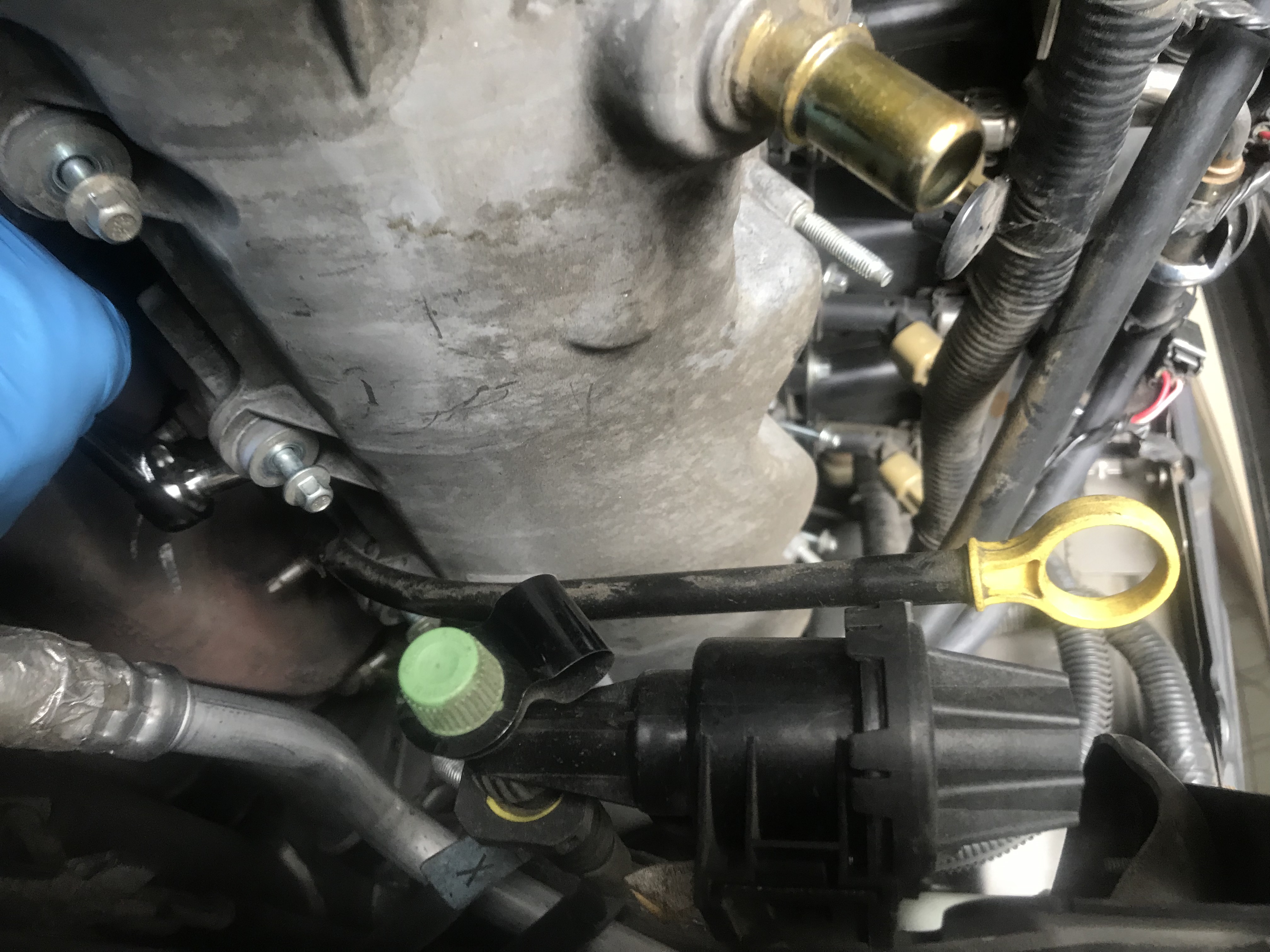
On the driver’s side, you’ll also need to remove the bolt on the oil dipstick so it can rotate out of the way.
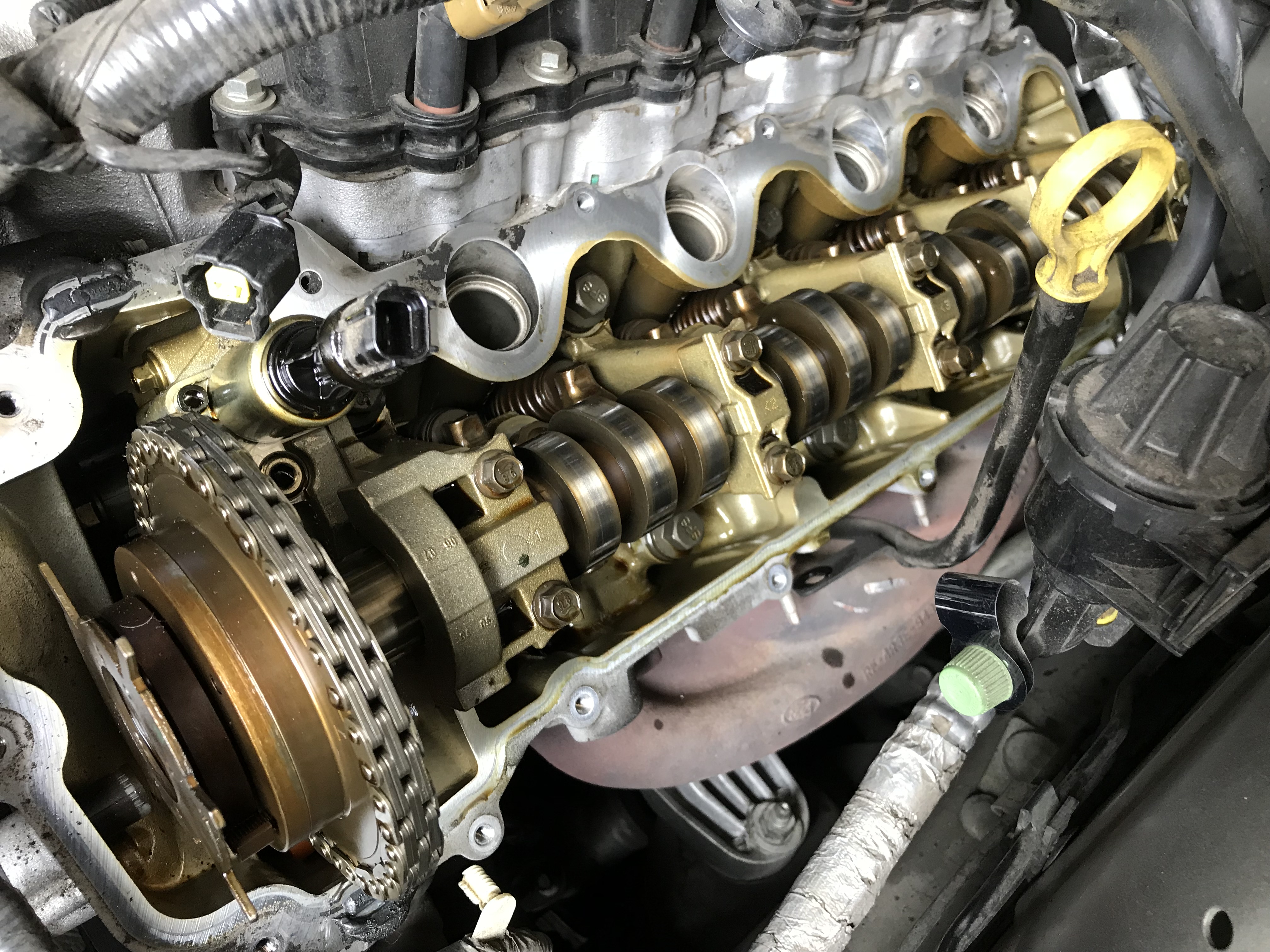
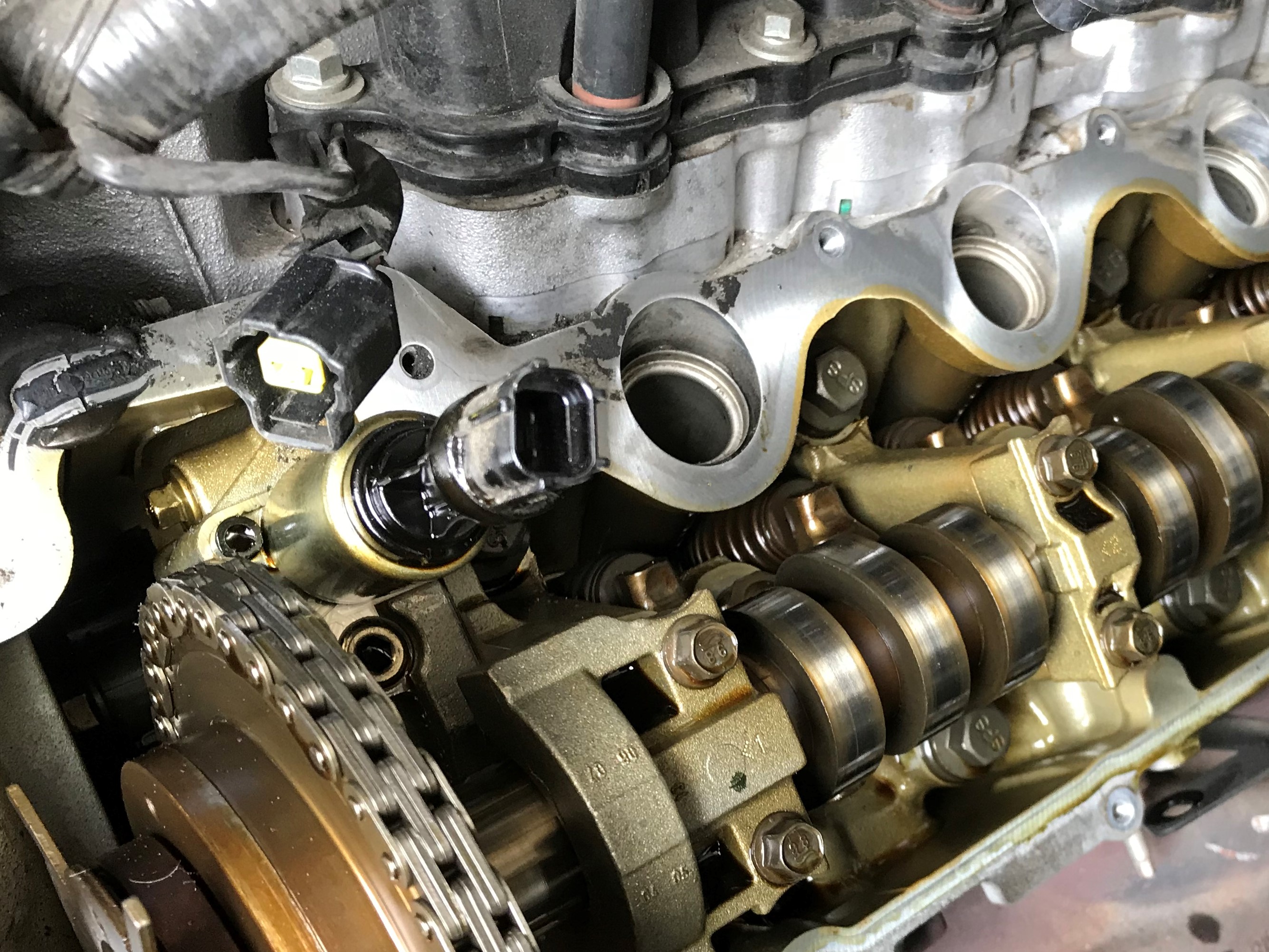
After a bit of finagling, the cover will slide right out and you’ll get your first look at whether or not your 3v has been running quality oil or not. We were happy to note zero sludge or build-up and nice light wear patterns on the cam lobes.
Glancing down the cover, the guides are looking good and not broken on this side. Fingers crossed!
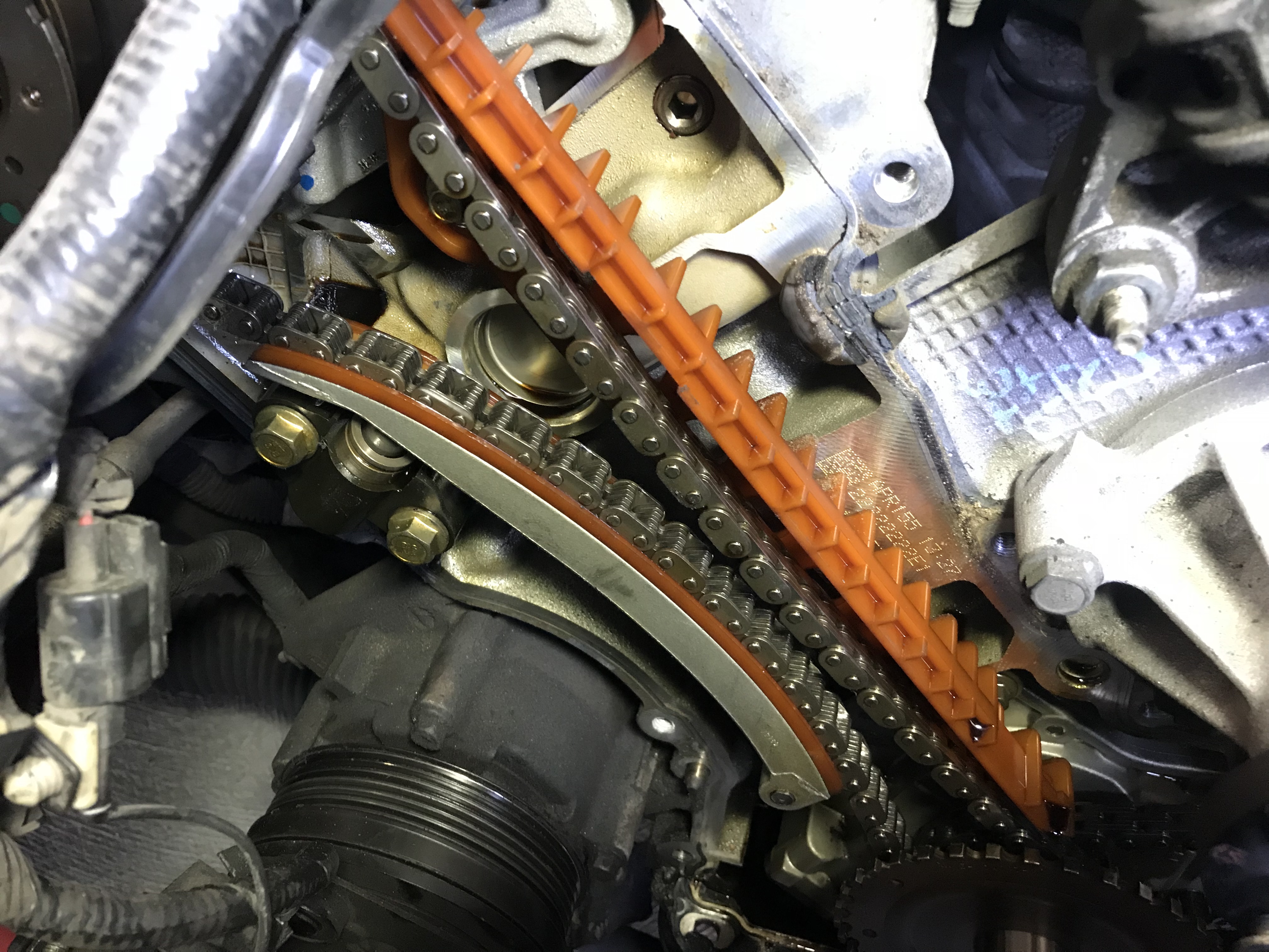
On the passenger side, we got our first look at the source of the noise. Notice the slack in the timing chain on the top. The guides looked complete on this side too.
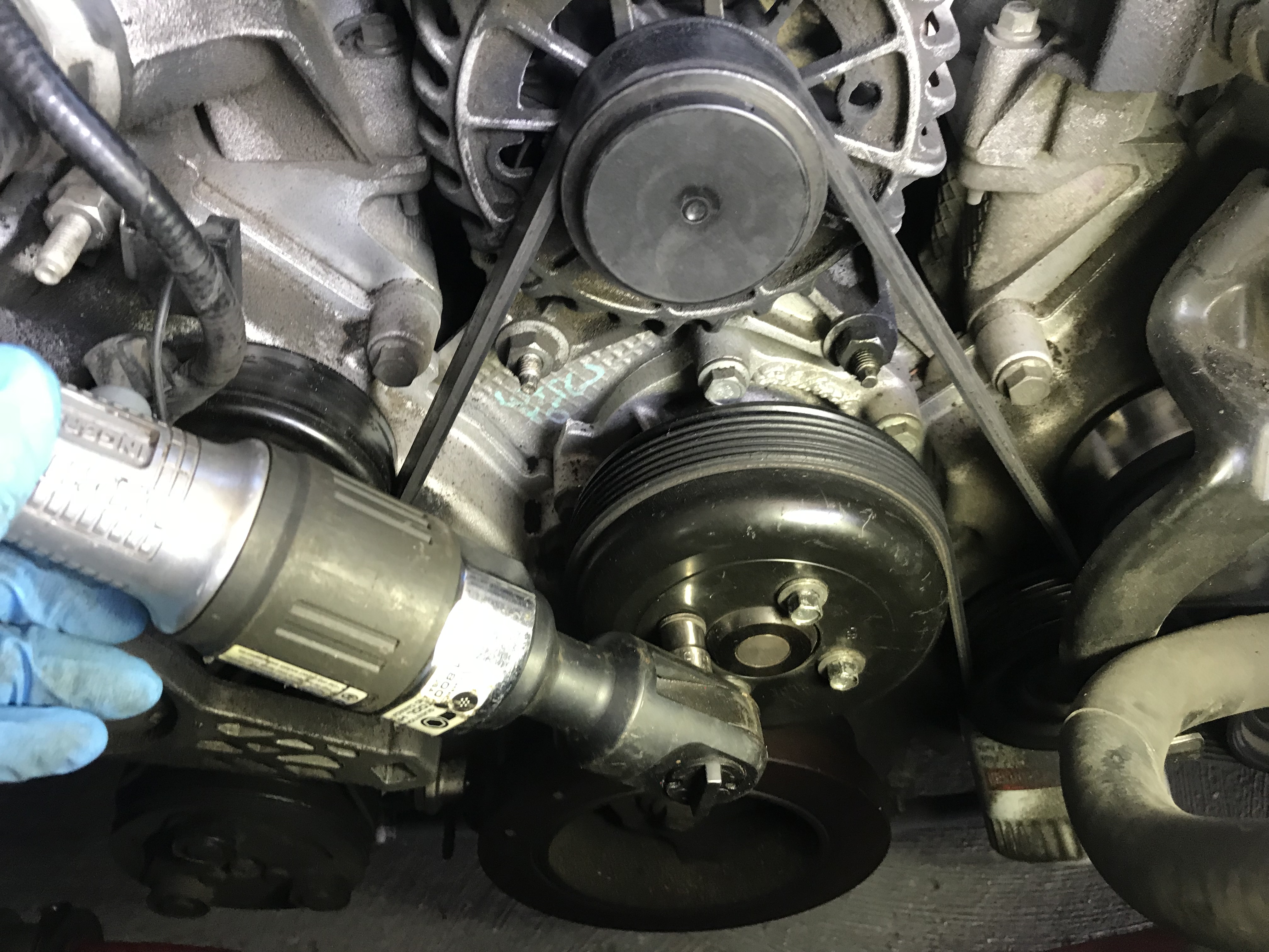
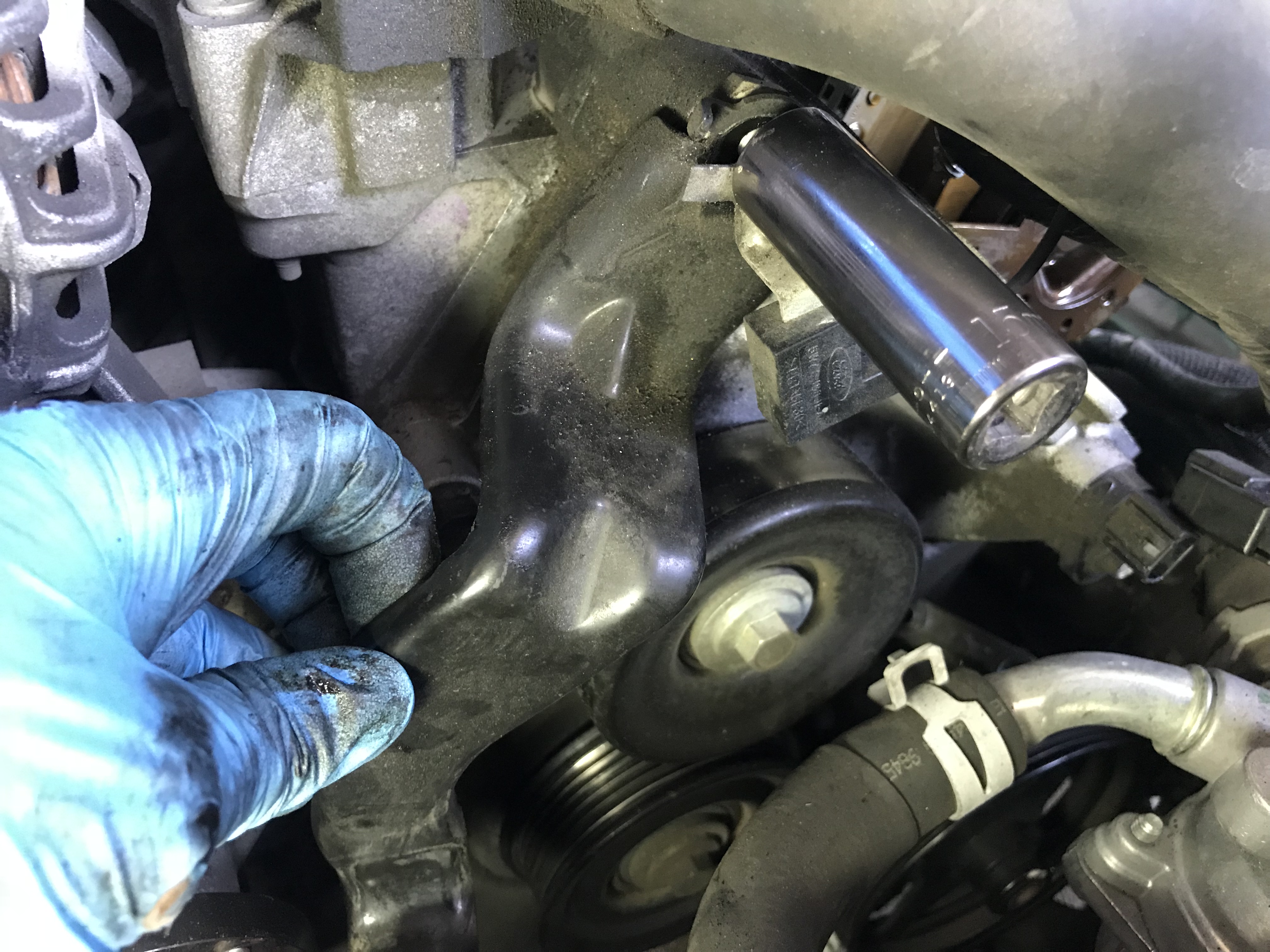
With the valve covers off, it’s time to attack the accessories. Break the bolts loose on the water pump before removing the serpentine belt. Pro tip: there’s no room for an impact, but a pneumatic or cordless ratchet will go a long way to speed things up with the numerous bolts.
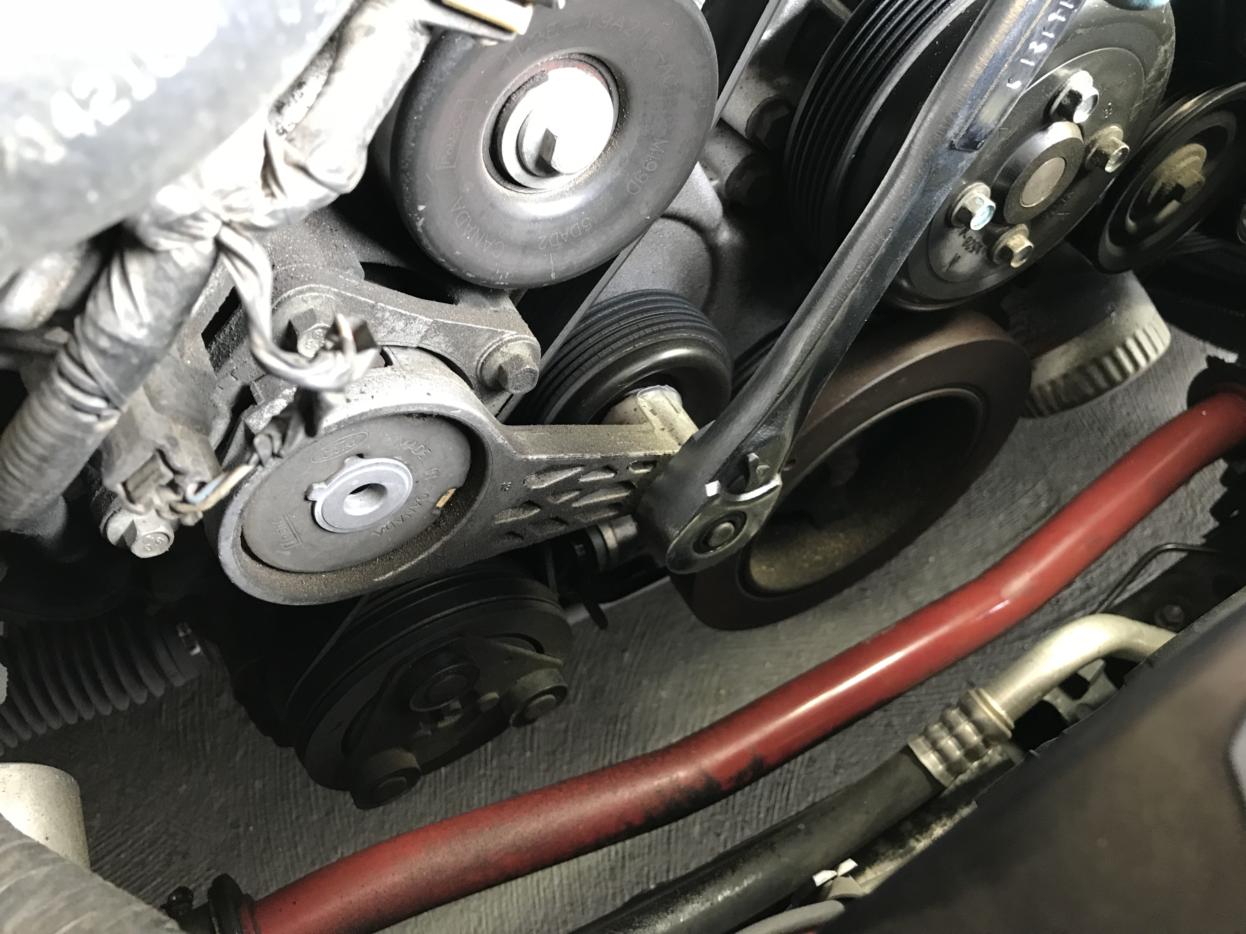
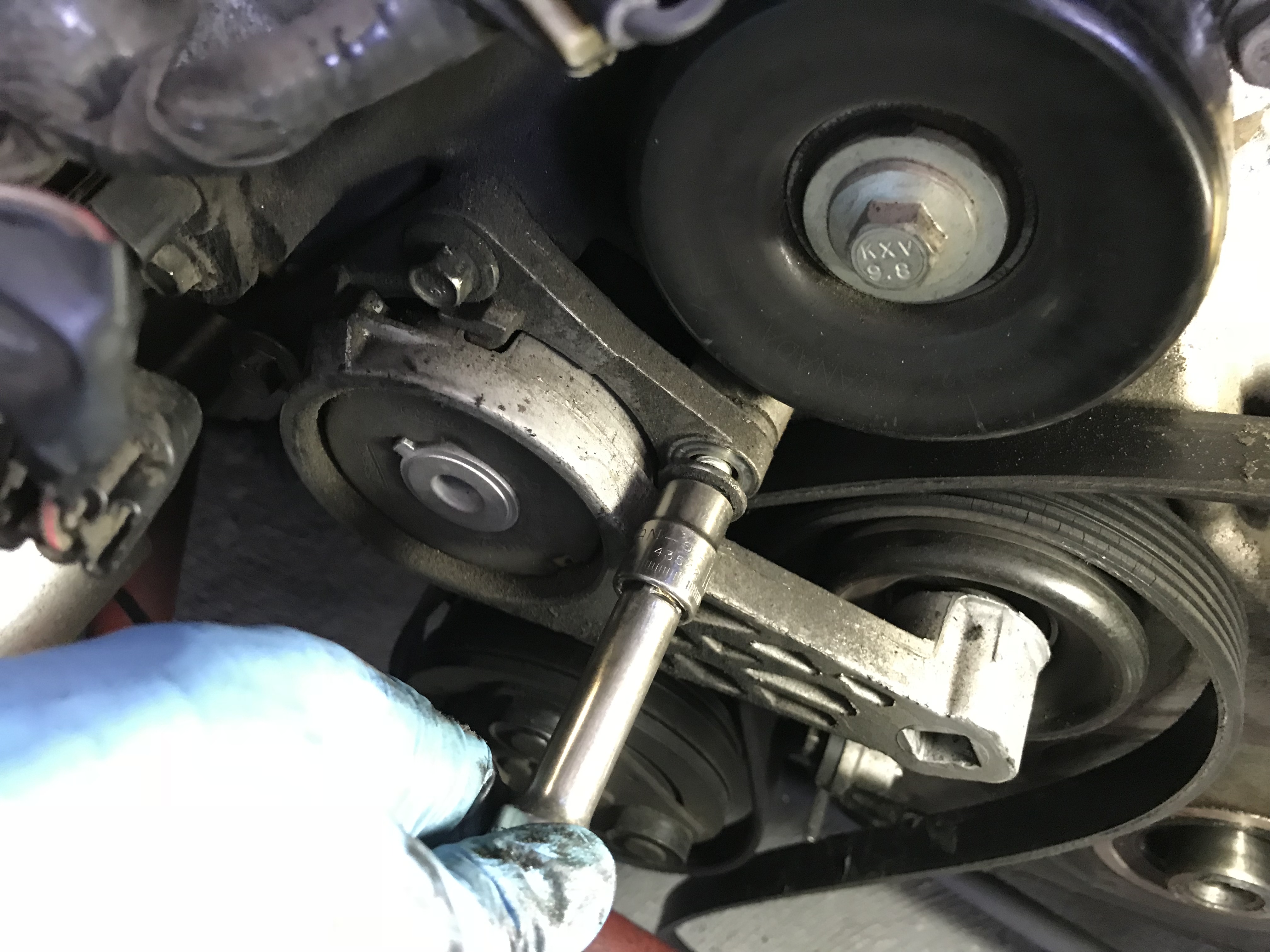
To remove the serpentine belt, a ½ drive ratchet will slide right into the tensioner. Push it downward and you’ll have enough slack to slide the belt off. It’s usually easiest to slide it off of the alternator and then work it off from there.
With the belt loose, three 10mm head bolts hold the belt tensioner on. Yes, that belt is very dry and cracked- it won’t be going back on.
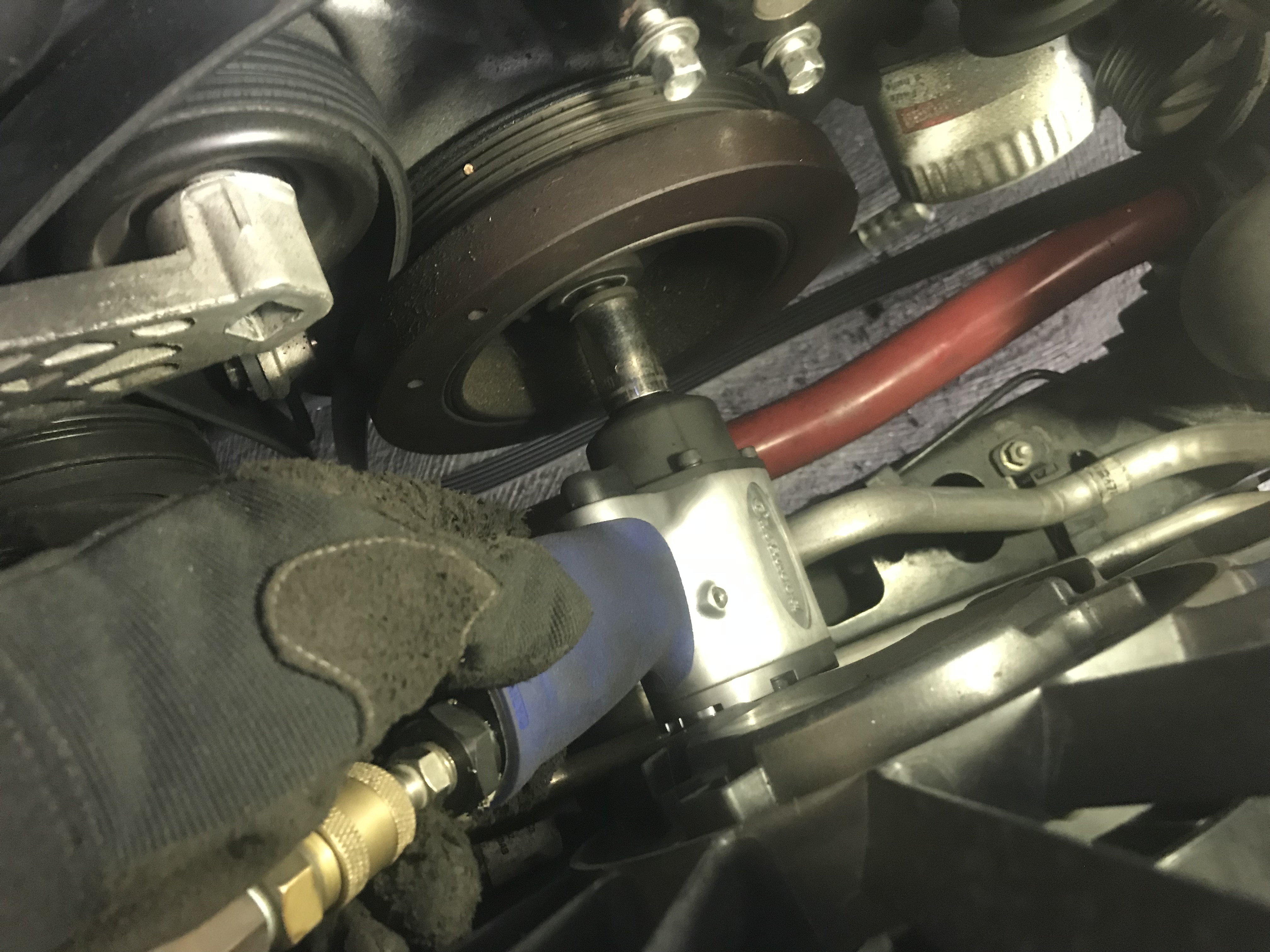
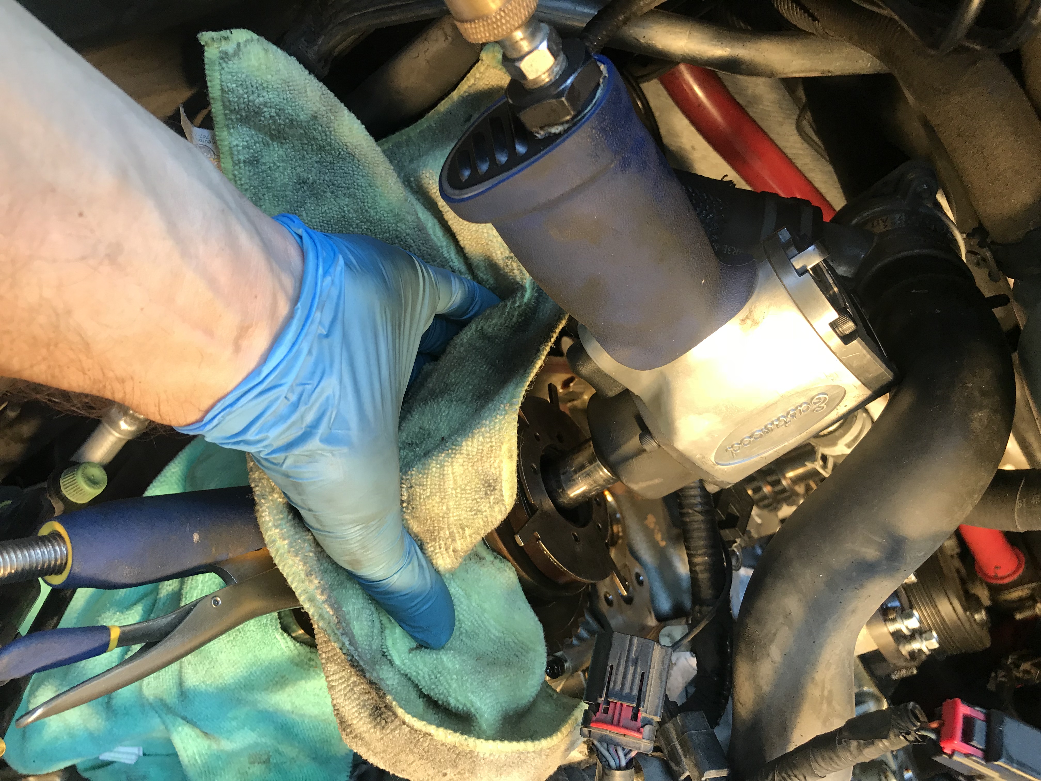
If you happen to have a compact sized impact, here is where it will really come in handy- breaking loose the harmonic balancer bolt. The one we’re using here is from Eastwood Tools, but Summit Racing carries many excellent options, like the very compact Aircat NitroCat.
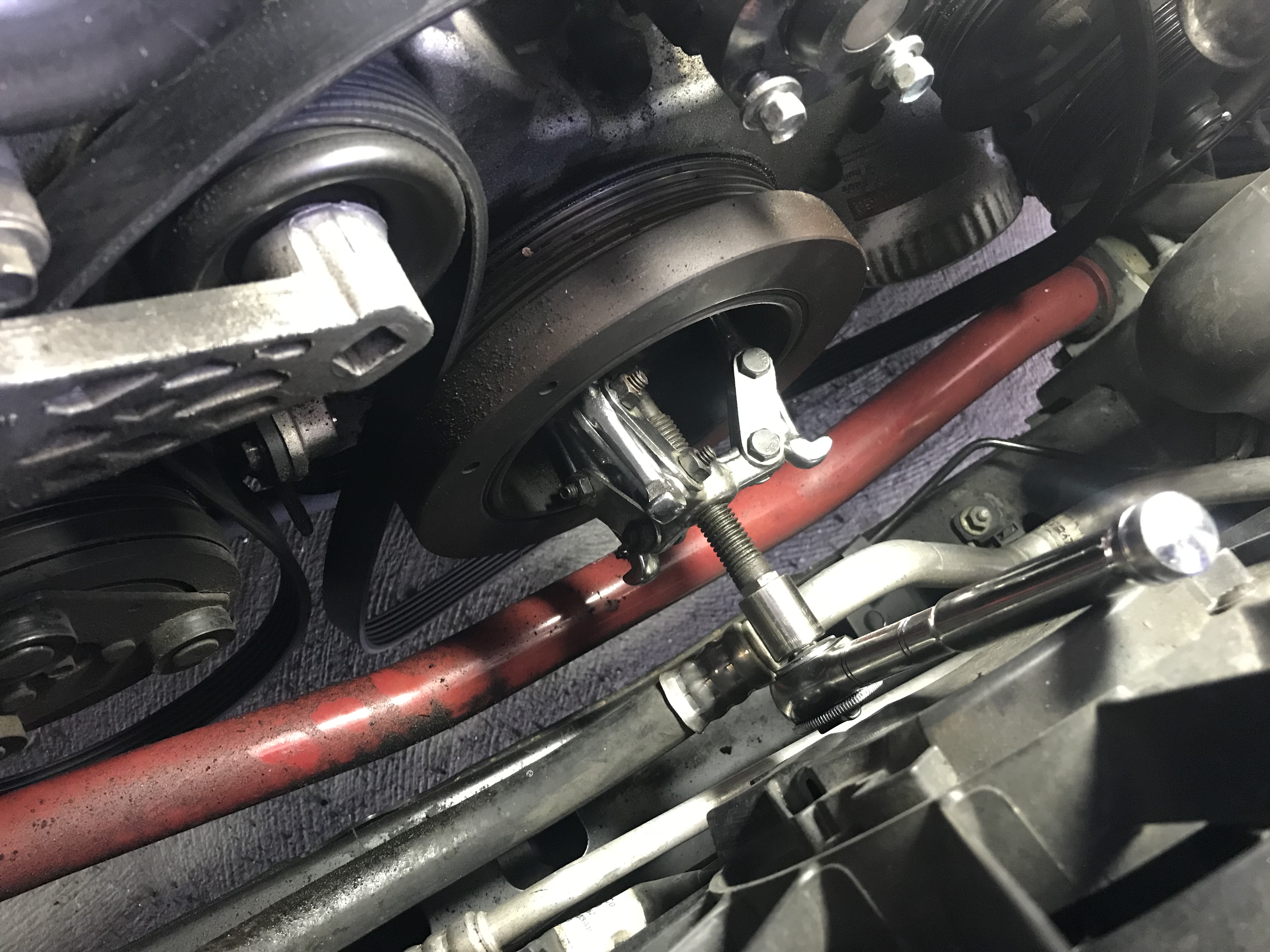
To remove the stock balancer, you will need a fairly compact three arm puller. The generic parts store one we’re using isn’t ideal, but it can be made to work. To save time and frustration, we’d recommend the OTC balancer puller.
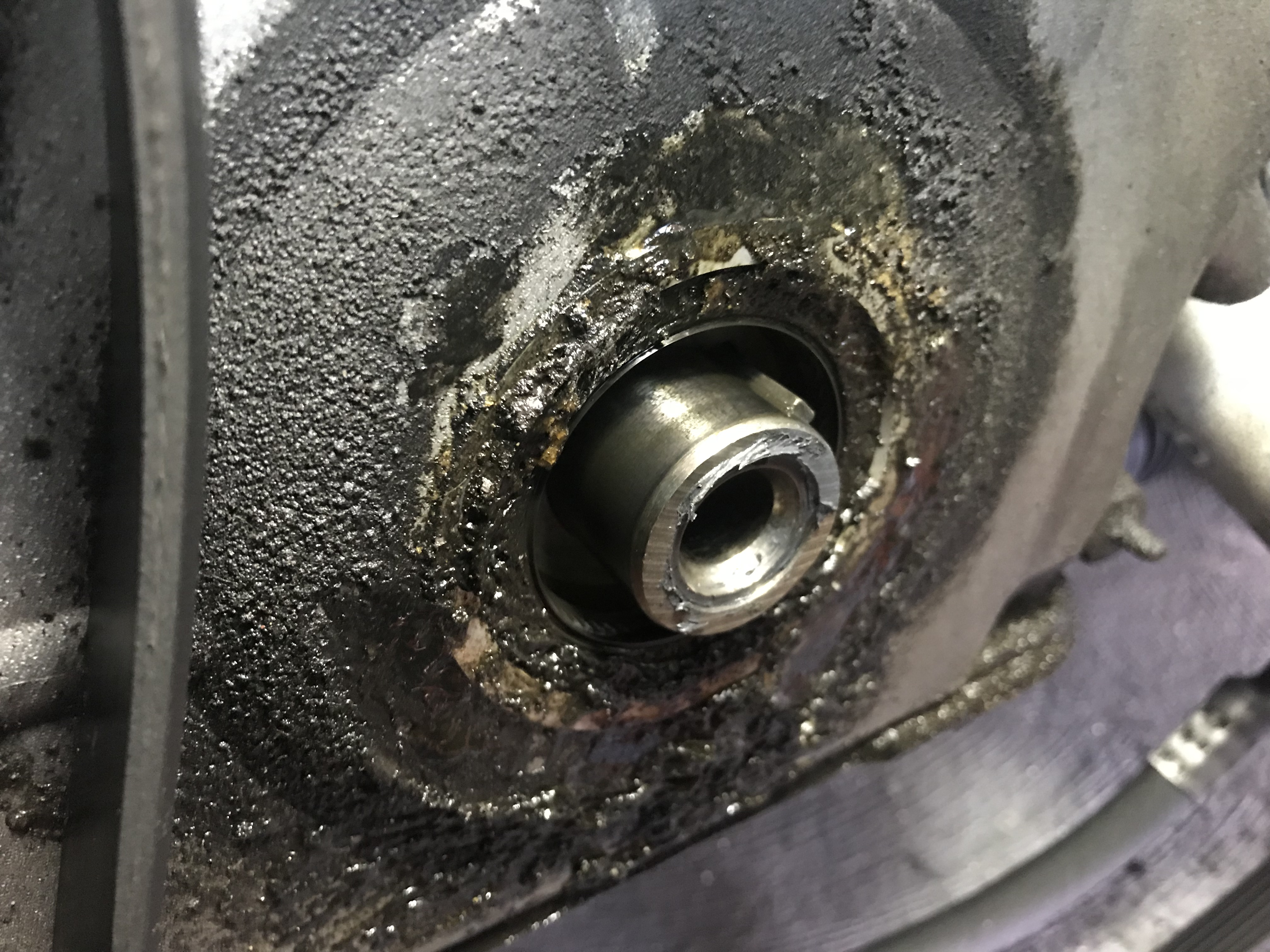
We knew we had a front seal going out from the spray line visible on the oil filter, and with the balancer off, we can see how bad it was. Replacing these is possible with the cover on, but it’s really a snap with the cover off.
Now it’s time to get to the real meat of the task; removing the cover bolts. There’s no trick here, except keeping track of the bolt locations. While the ones in the center of the V are the same, the bolts in the bottom corners near the pan and the ones up near the valve covers are unique and should be reinstalled where they came from. The idler pulleys should be removed at this time as well.
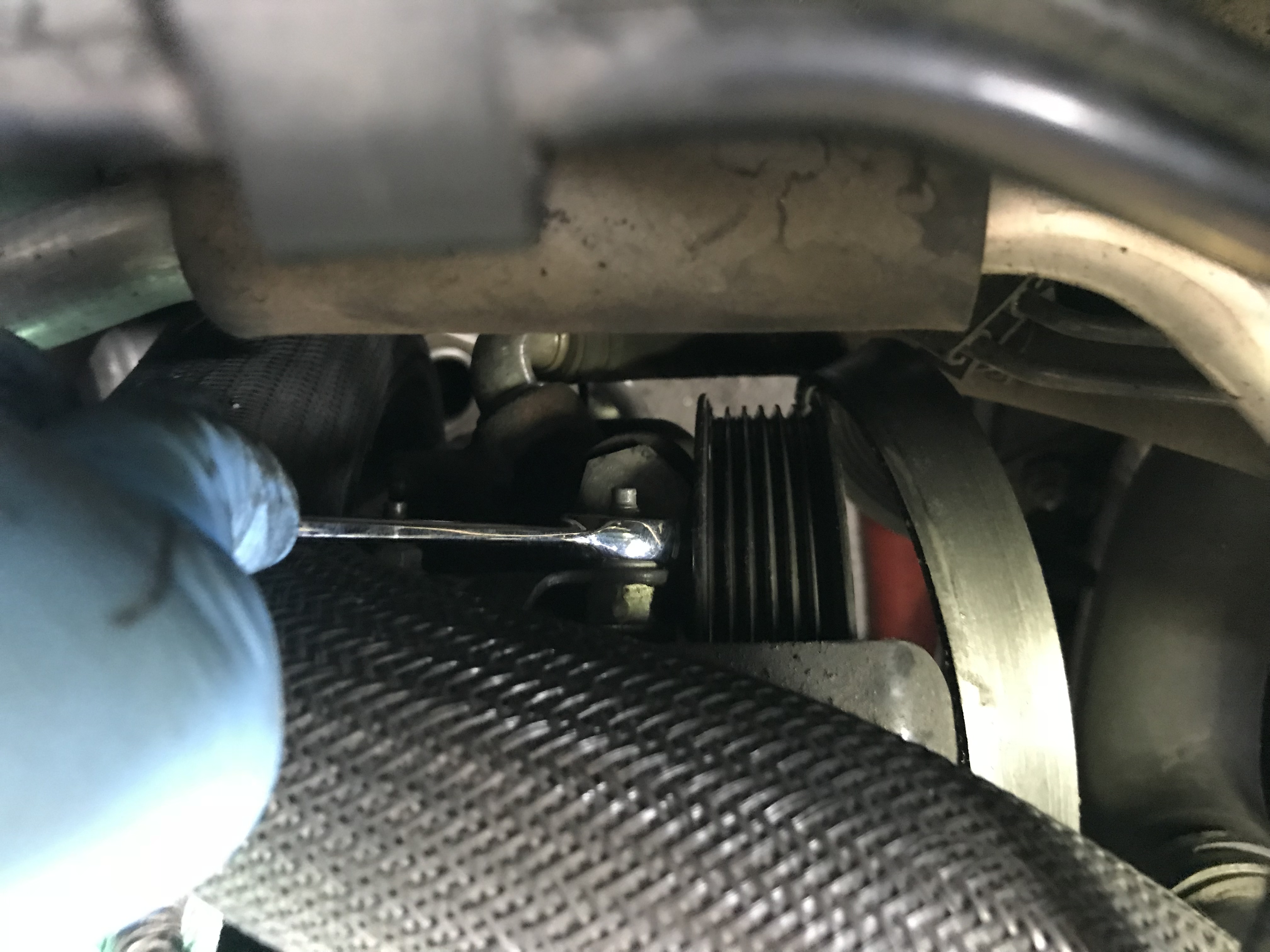
The power steering pump bolts also need to be removed. It’s tight, but if you have a ratcheting wrench, it’s not a big deal. The two bolts visible in the pic are easily reached, but there is a third one below the pressure hose that takes a bit more patience and short throws with the wrench to back it out.
With the front of the cover clear and all the front bolts removed, there are actually still four more bolts to go; they’re on the bottom of the cover holding it to the pan. Fortunately, the pan gasket will reseal and doesn’t require replacement. Once you have those pan bolts removed, it’s time to pull the cover!
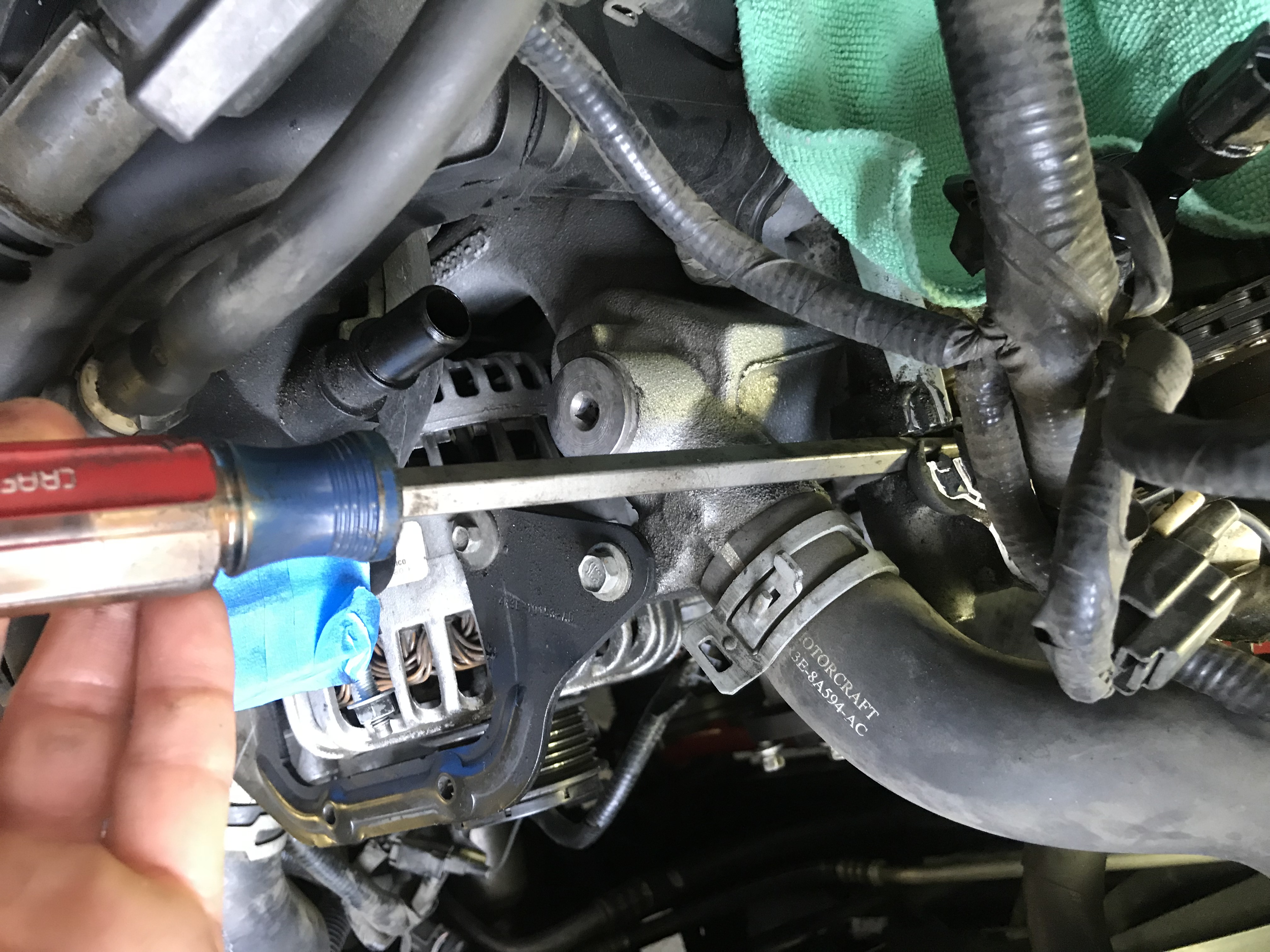
If your front cover has never been removed before, it’s likely going to require a little persuasion. A wedge or a wide flat head screwdriver can break the seal by tapping it around the top edge of the cover where it meets the block and heads. Be cautious to not score the block or cover.
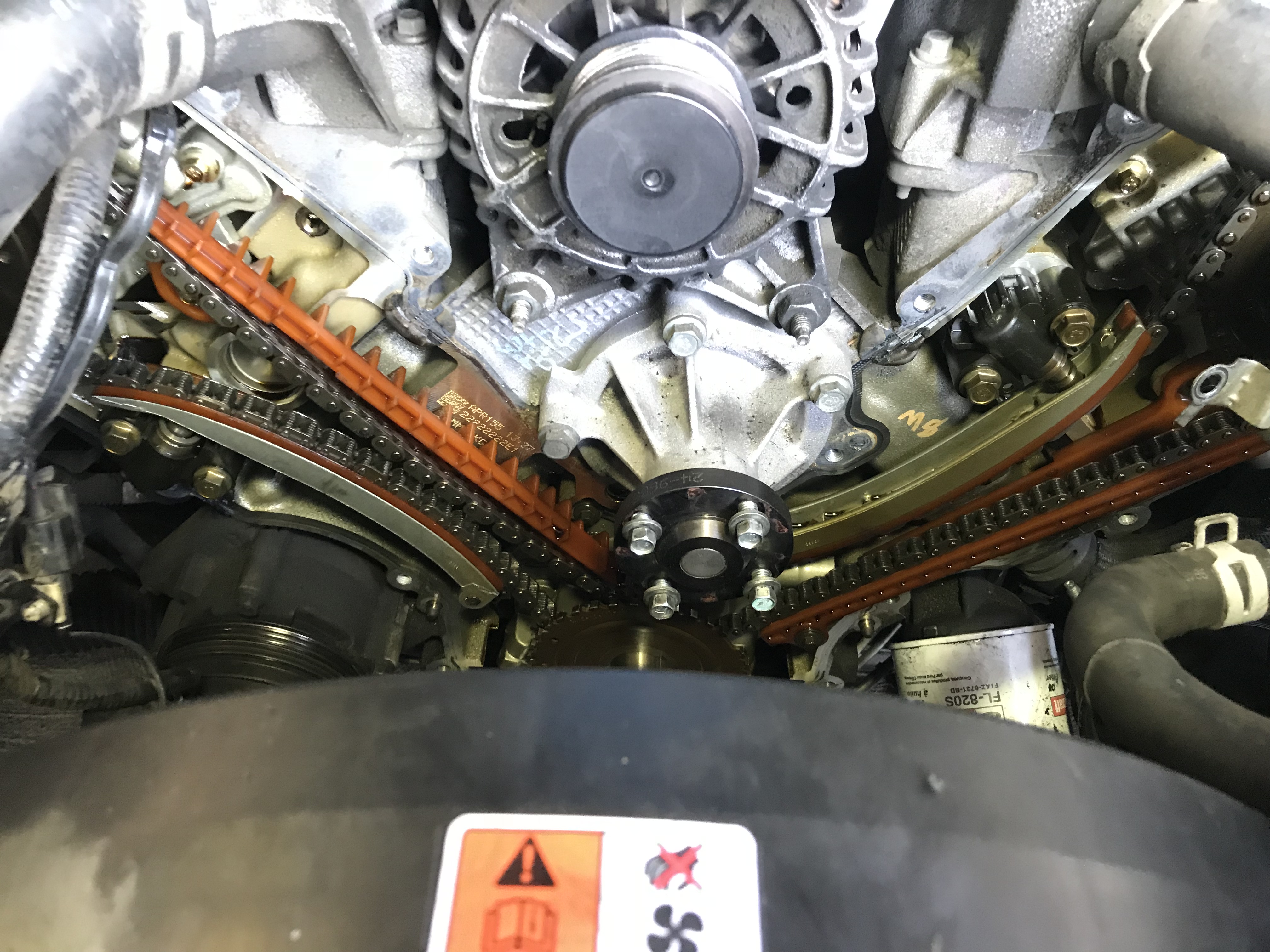
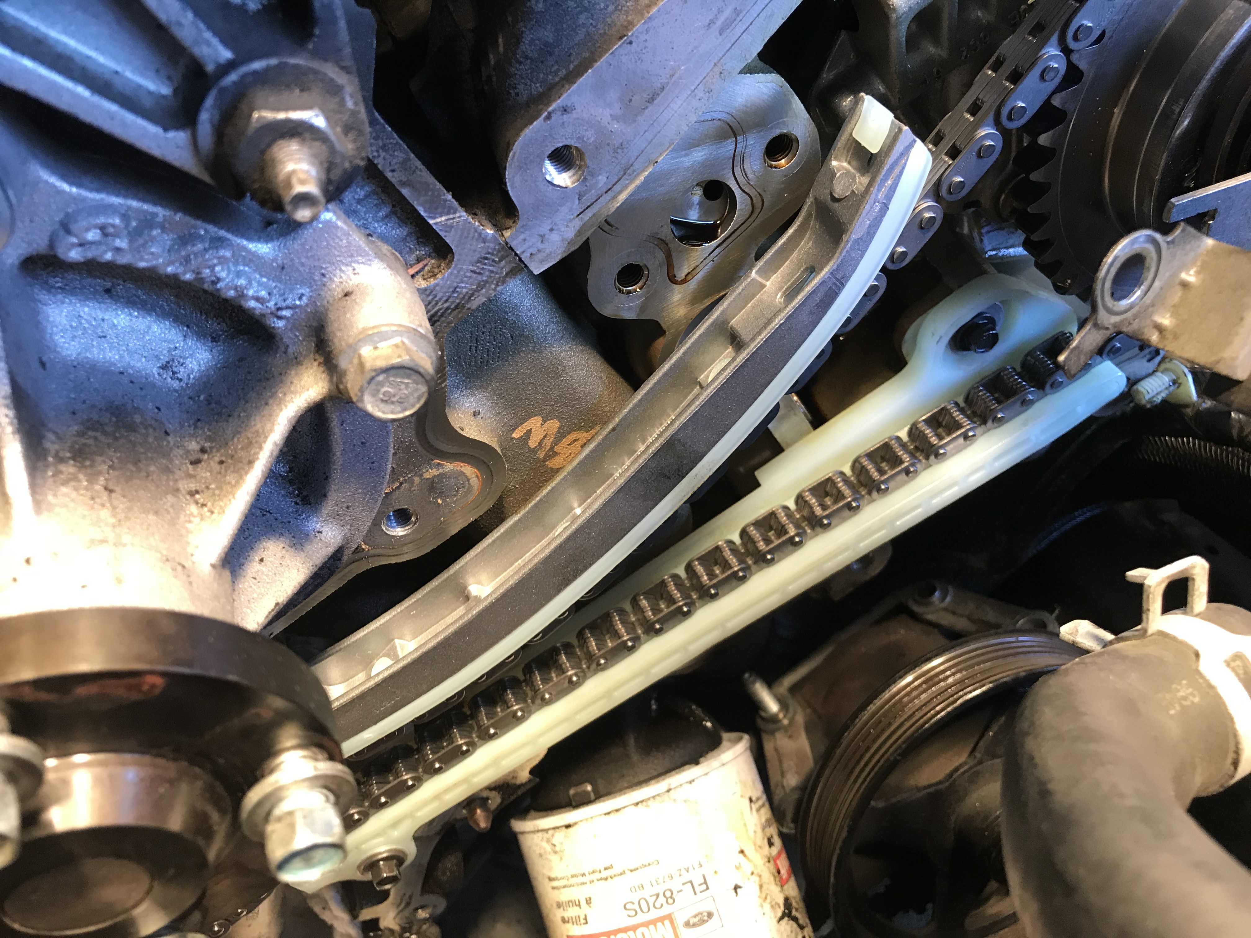
Score! All the chain guides are complete and in place! It’s actually really common on high mileage engines to see pieces missing, which of course have fallen down into the oil pan.
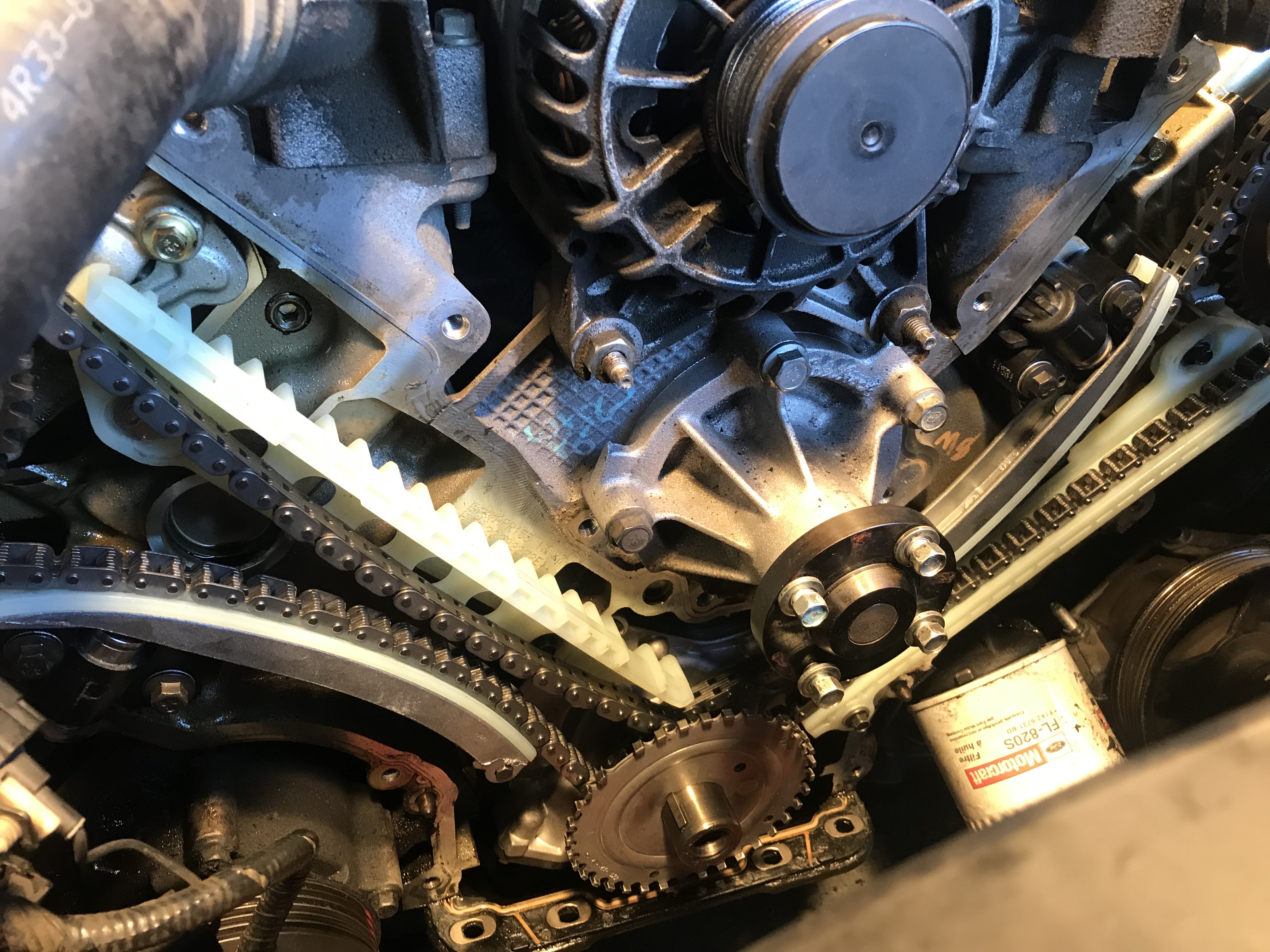
Here’s a closer look at the slop in the chain on the passenger side. That’s quite a bit, let’s see if we can figure out what’s going on here.
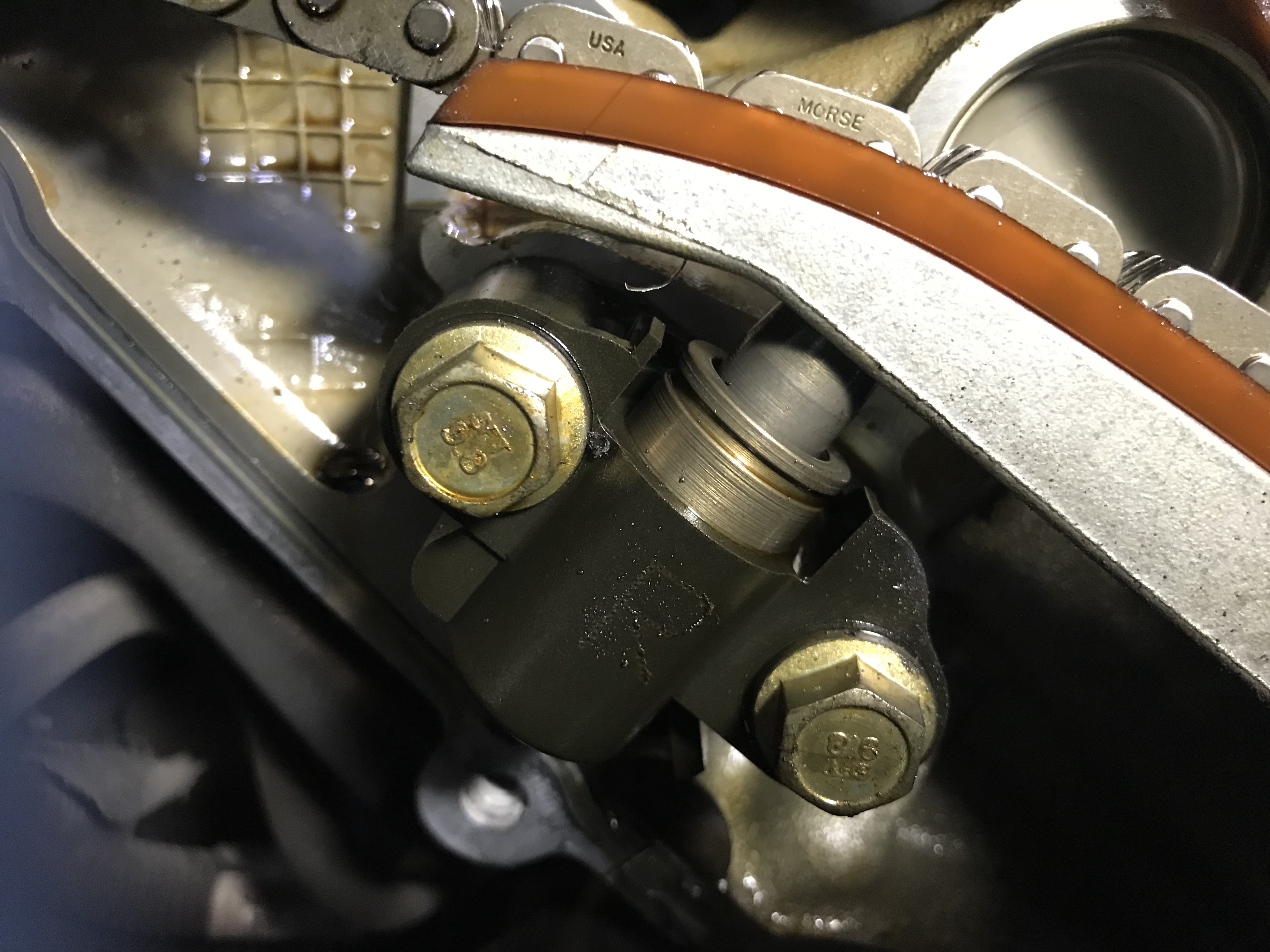
We knew the tensioners would slowly leak down when the car had been sitting for a while from the cold crank rattle, but we had assumed that constant noise was from completely failed tensioners. However, upon closer inspection we found both to be almost fully extended. The plot thickens.
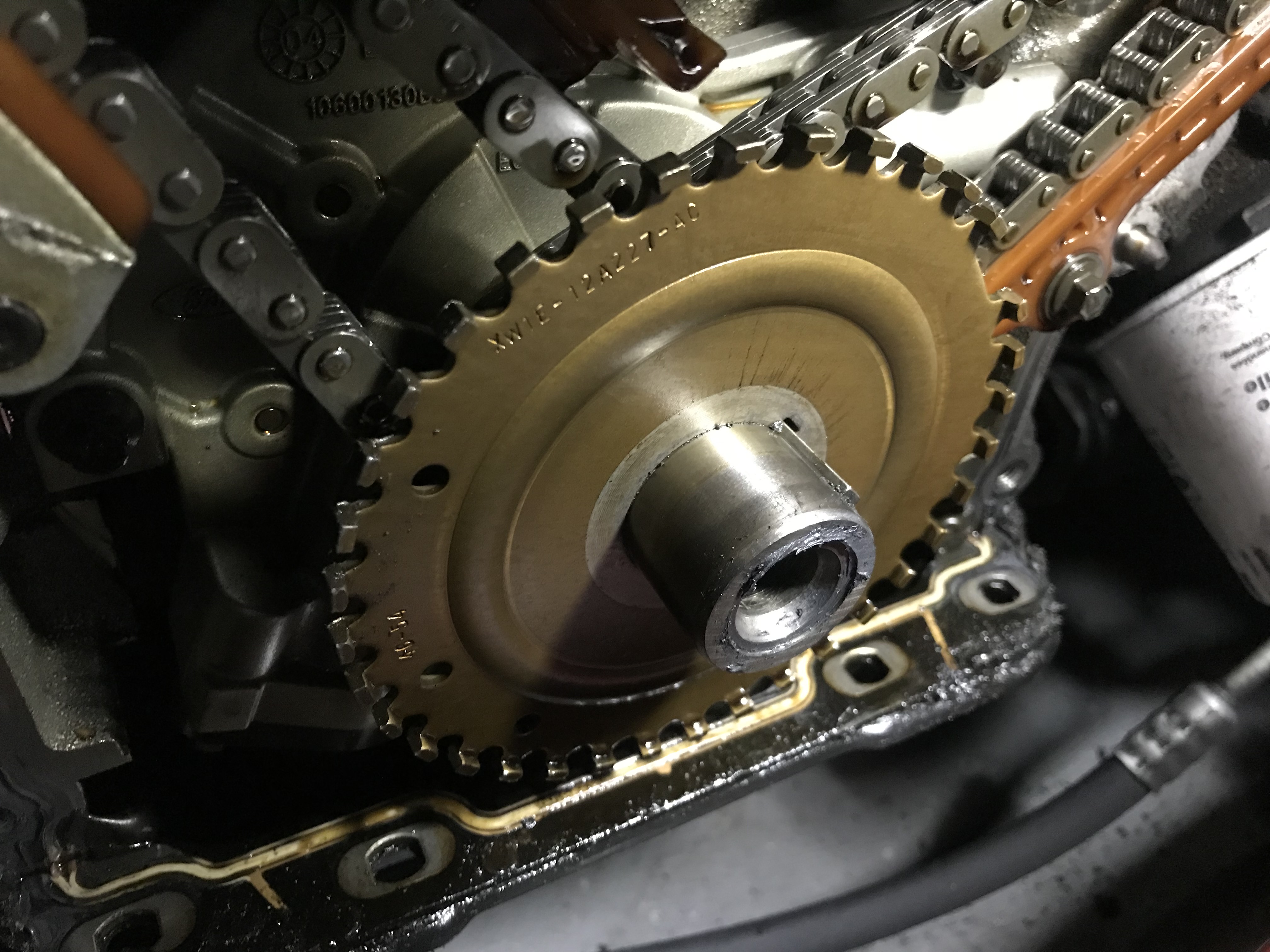
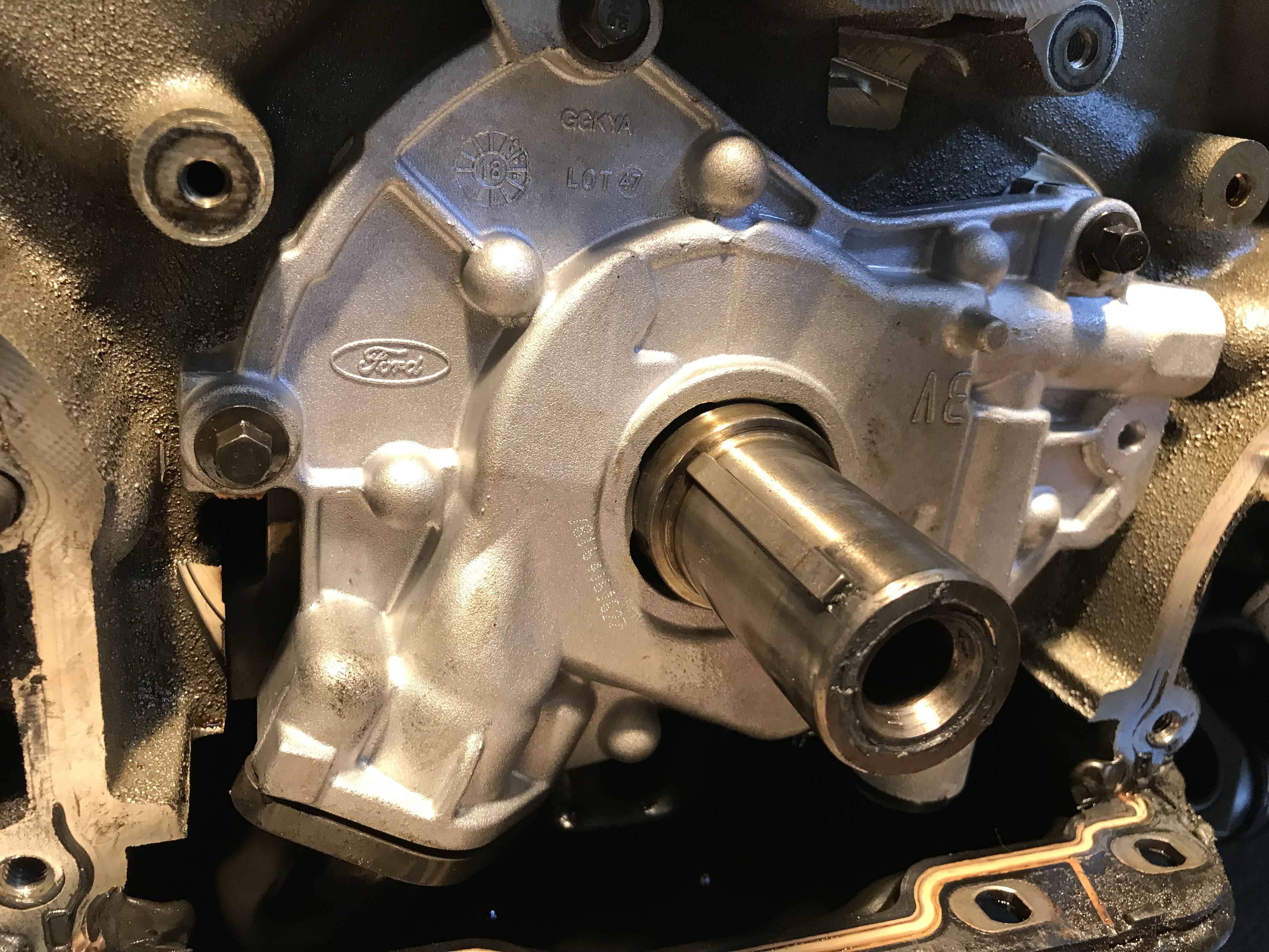
Believe it or not, it’s only the harmonic balancer that retains the reluctor wheel, which is why it’s critical to get it fully torqued down during the reinstall. We’ll go over the tightening sequence to get it right.
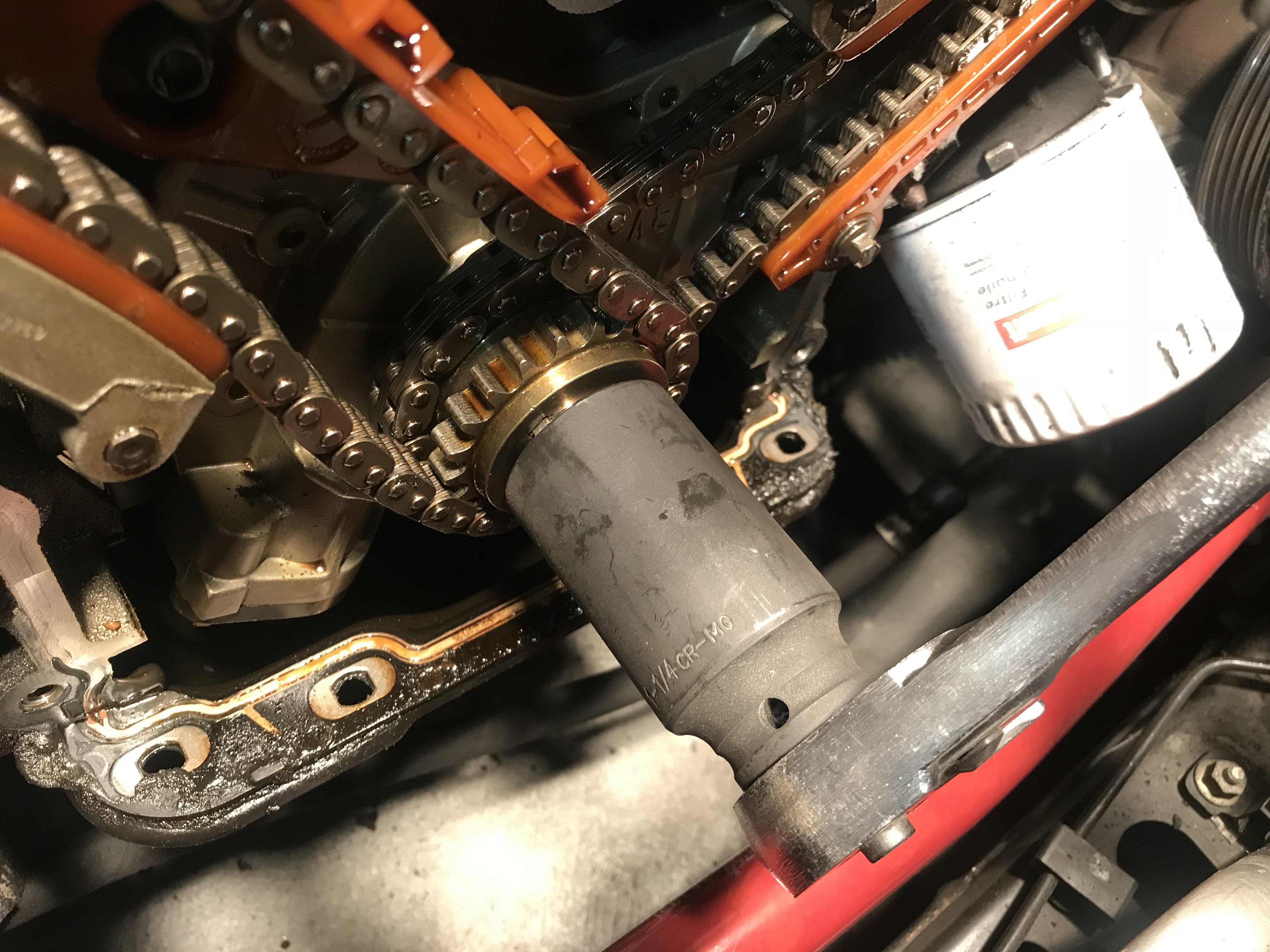
With the reluctor out of the way, it’s time to set the cam timing before we touch the chains. A 1 ¼ socket fits like a snug glove over the crank snout and locks onto the keyway. Use a ½ drive ratchet with good leverage, because you’re going to be cranking the engine over. You can pull the spark plugs to make this easier, or just settle in for an arm workout.
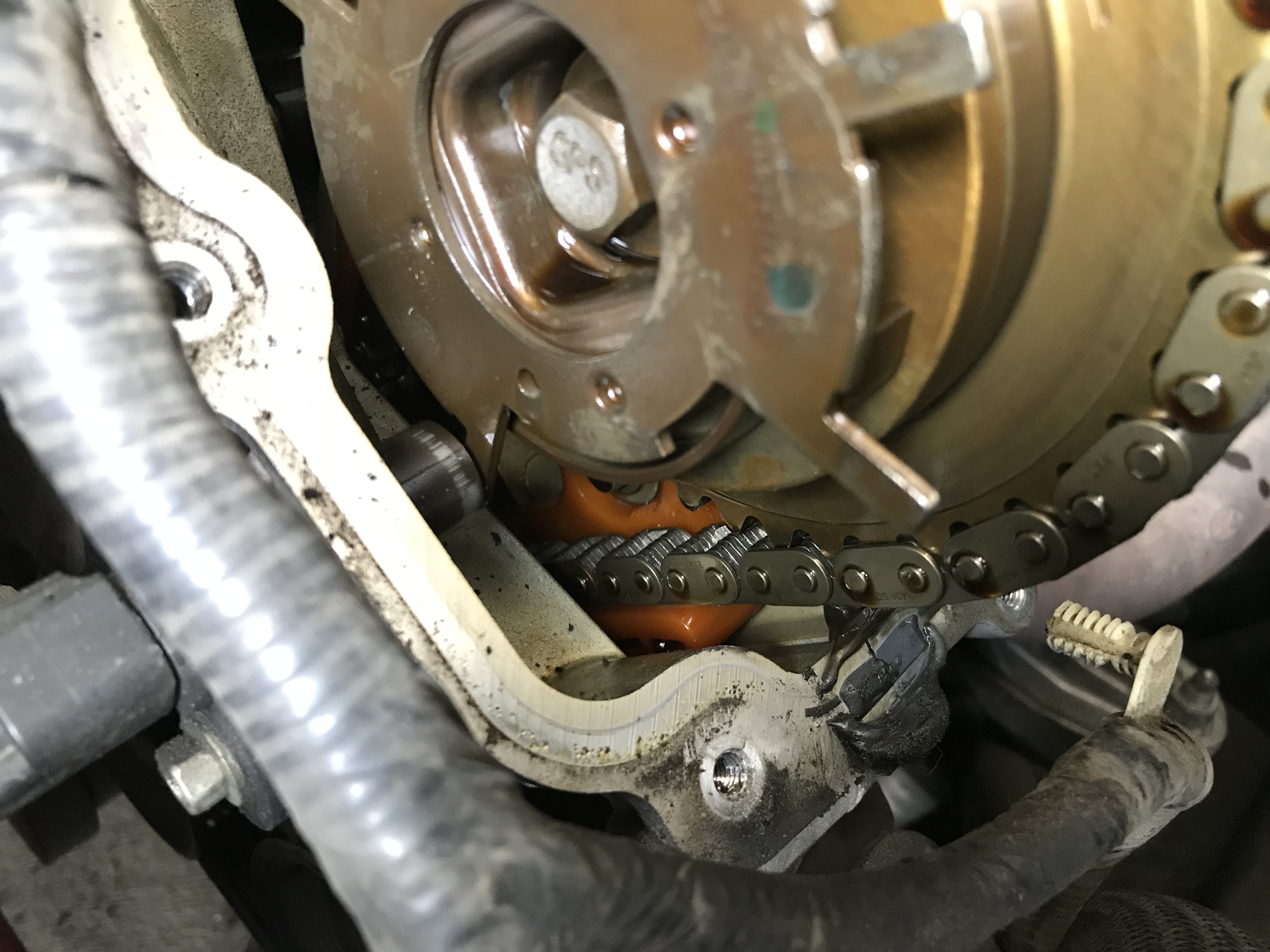
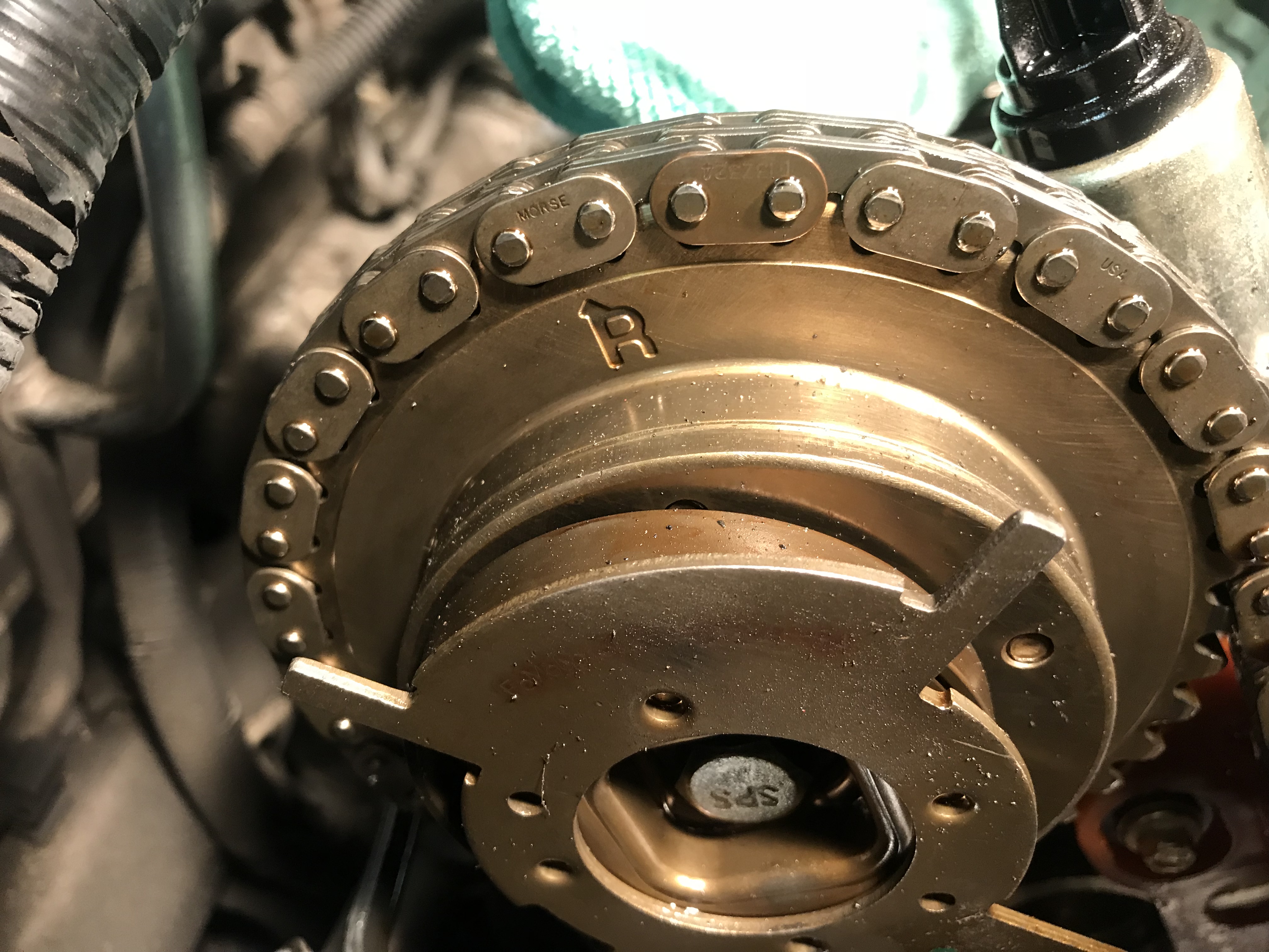
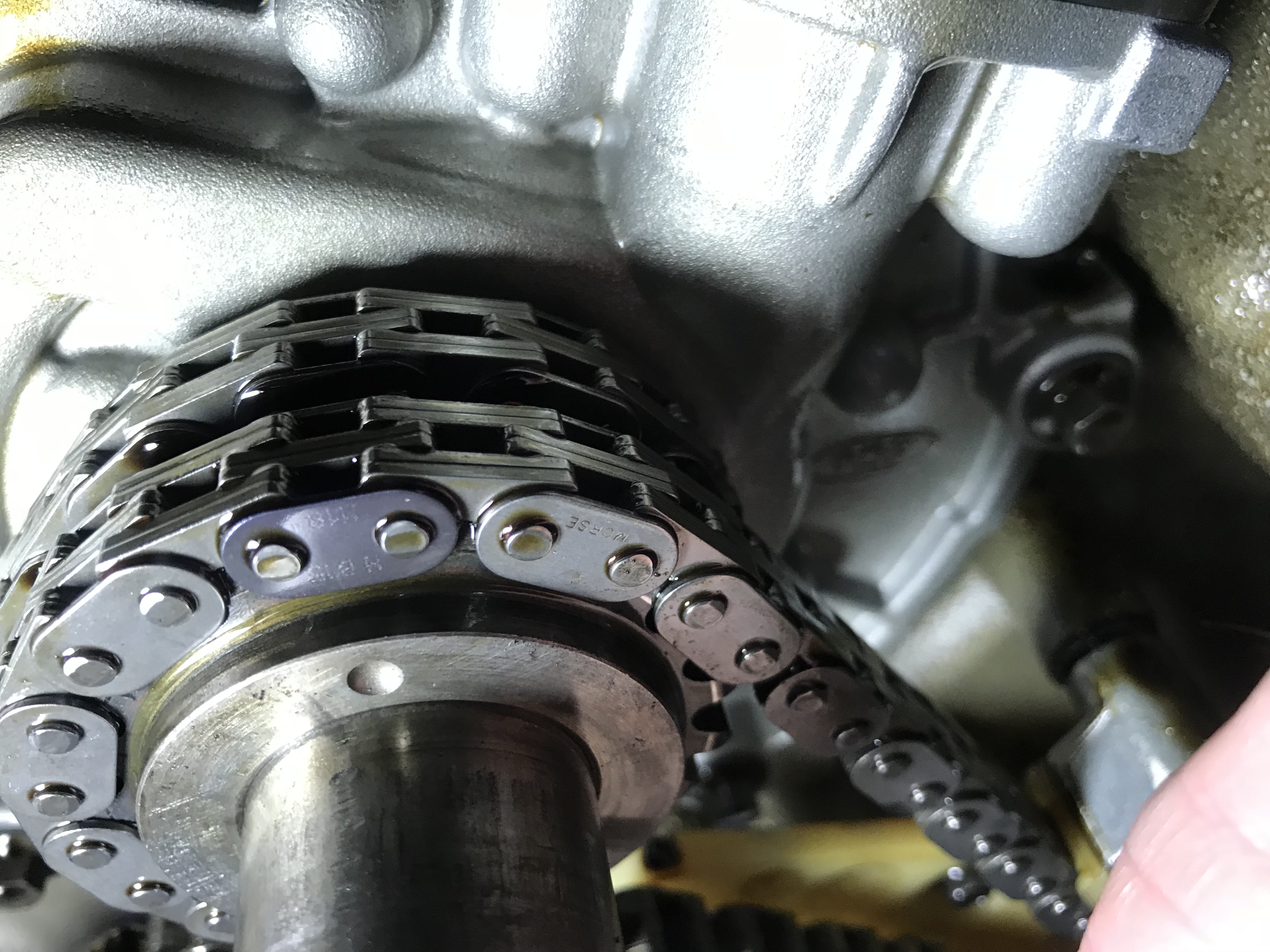
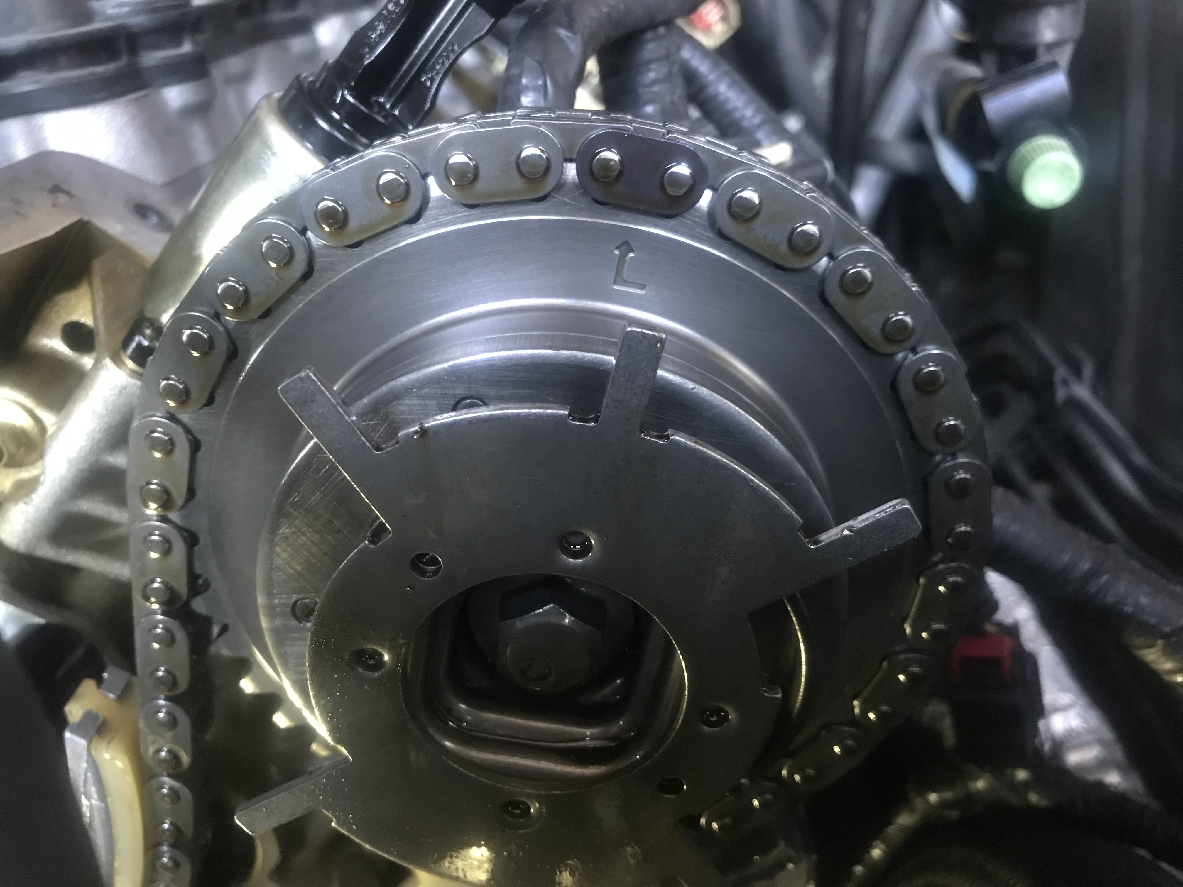
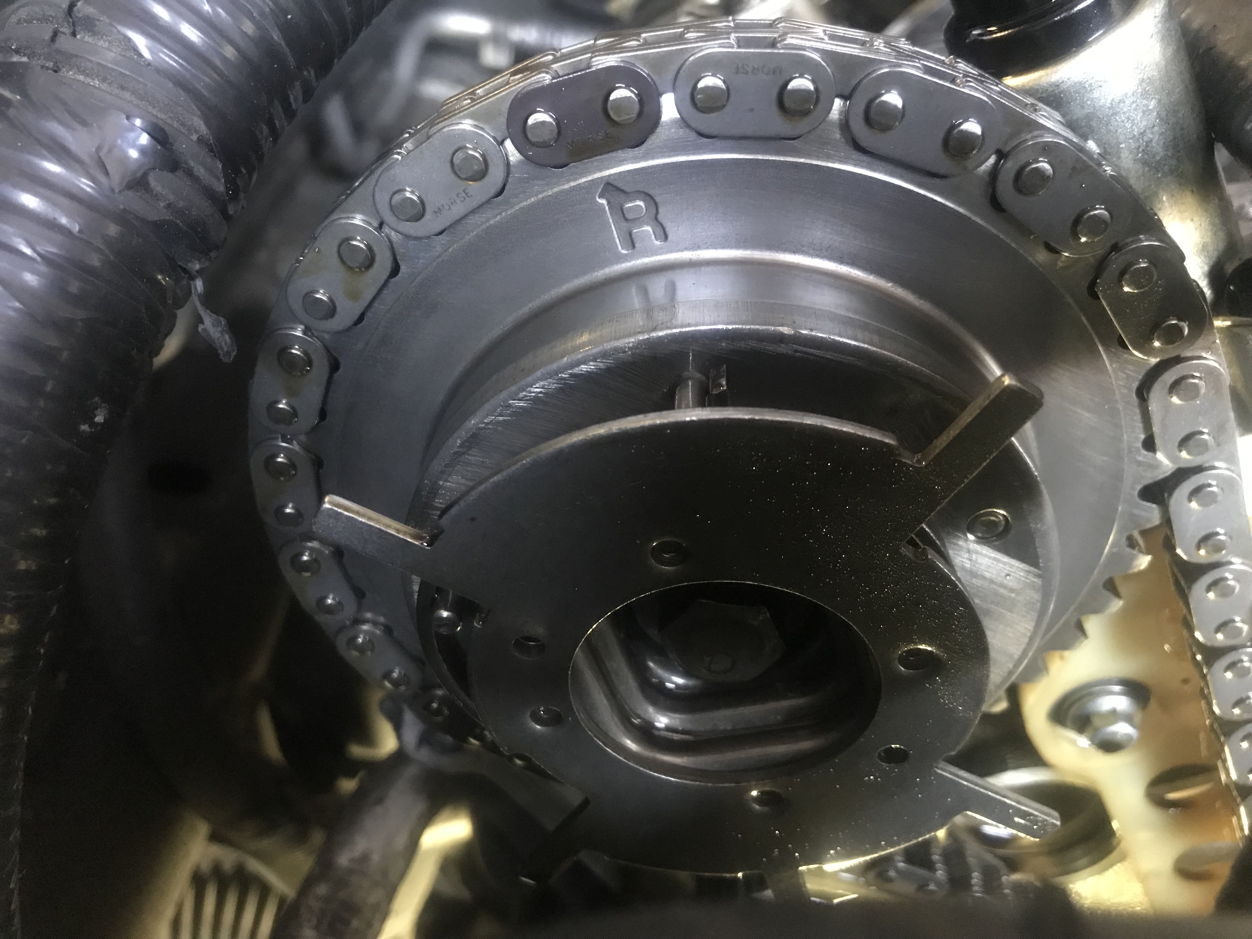
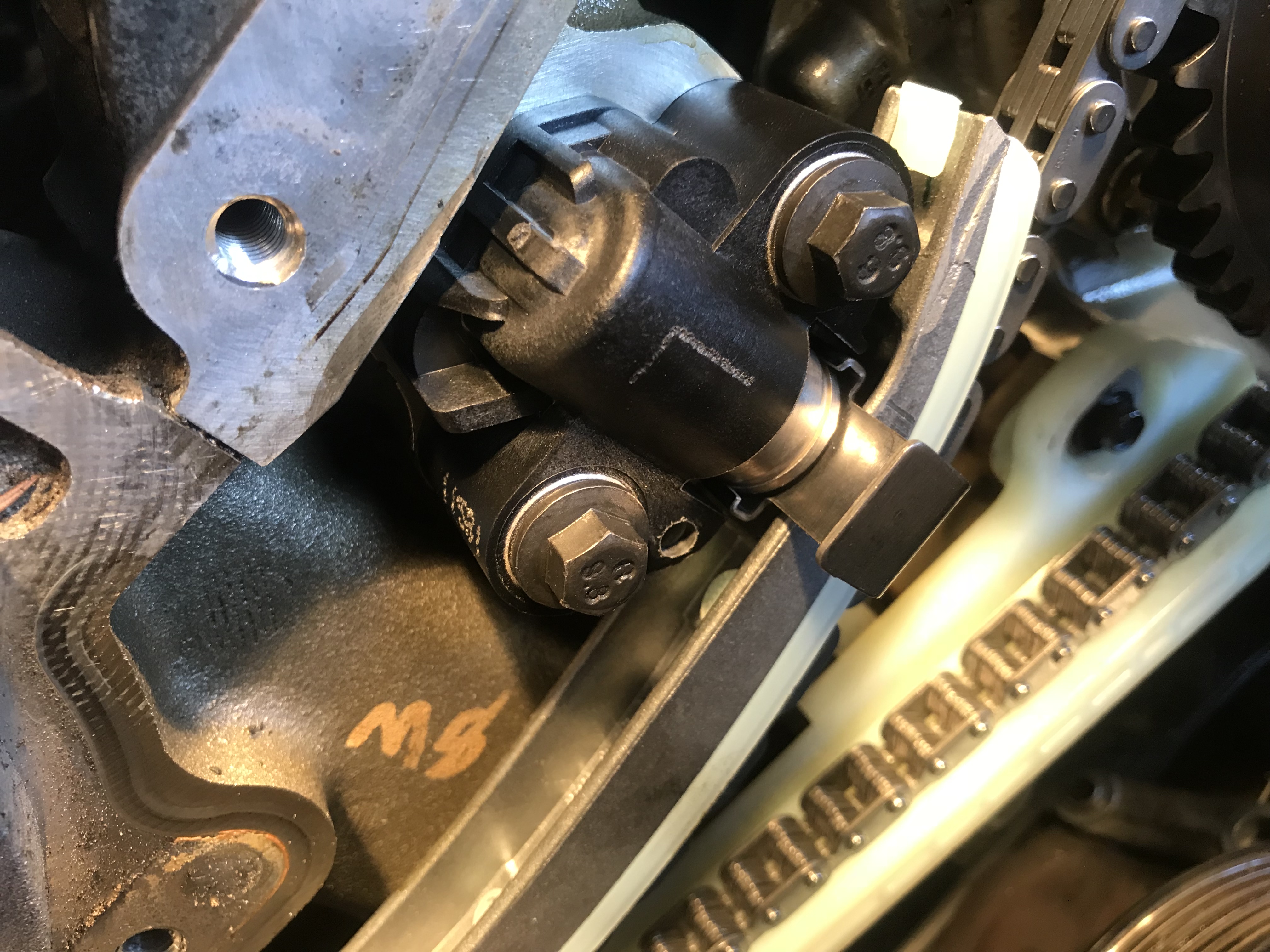
There’s really no magic to timing a 2 or 3V 4.6; you just have to line up the correct marks with the dark links on the timing chain. The cam phasers have both and L & R marks, so it’s important to know which to use. L & R are always referenced from the driver’s seat, so as you’re looking at the engine the cam on your left (passenger side) will use the R mark, while the cam on your right (driver’s side) will use the L. This is the passenger cam phaser, and we still have some rotating to do to get the dark link properly lined up.
Not only do we have to properly line up both cam phasers, we also have to line up the second dark chain links on both chains with the dot on the crank sprocket. When properly aligned, the dot will point straight down at 6:00 o’clock with the dark links straddling it while both cam phaser marks also have a dark link straddling them. Sounds complicated, but really it will all line up eventually as you crank the engine over.
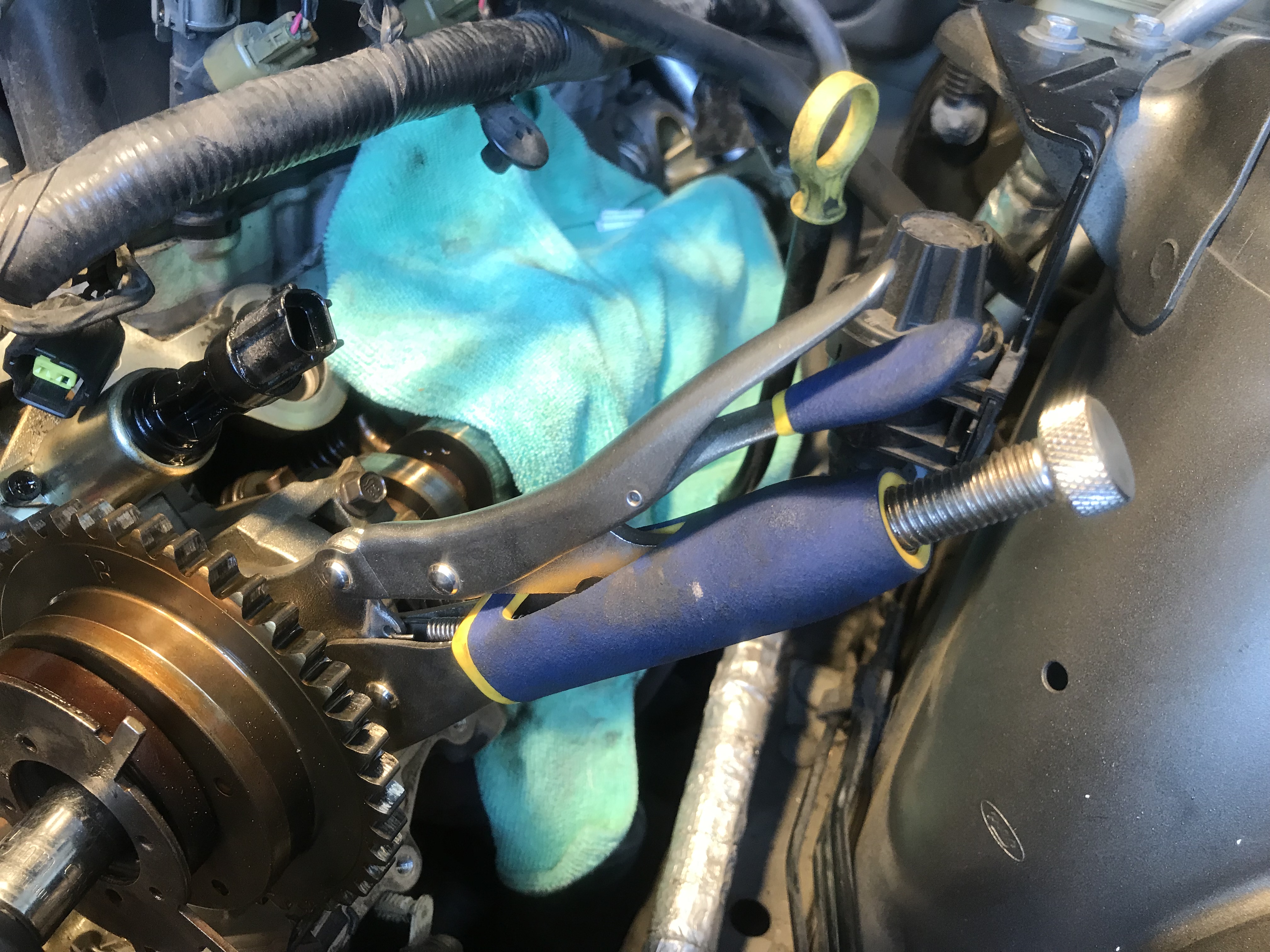
Since we’re not removing the springs & followers, the cams lobes are under pressure and will move to the closest equilibrium, meaning it will throw off your carefully synched timing. There are a couple of ways to tackle this. One, is to lock a pair of vise grips on the cam just behind the phaser. Make sure to brace the vise grips properly against the head and on the side the cam wants to rotate. (ignore that our chain is already off here, we forgot to take a pic beforehand. Yours should still be on.)
You might be wondering why we didn’t use a tool like this convenient OTC cam lock (PN: OTC6477). While these are great for 2V engines, and there is a versions for 4V, we’re not aware of one that fits the larger diameter cam used in a 3V. By the way, this is not our engine, so don’t @us about the grime.
So how do you know which way the cam is wanting to rotate? Well, the easiest way is once you have the cams and crank timed, just remove the tensioners. With the chain still in place, the cams will rotate slightly from the slack created, but not far. Remove the tensioner slowly, but keep pressure against the chain guide and note which way the cam wants to move and then lock the vise grips behind the phaser to prevent further movement. If you want to be extra careful, use two vise grips opposing each other.
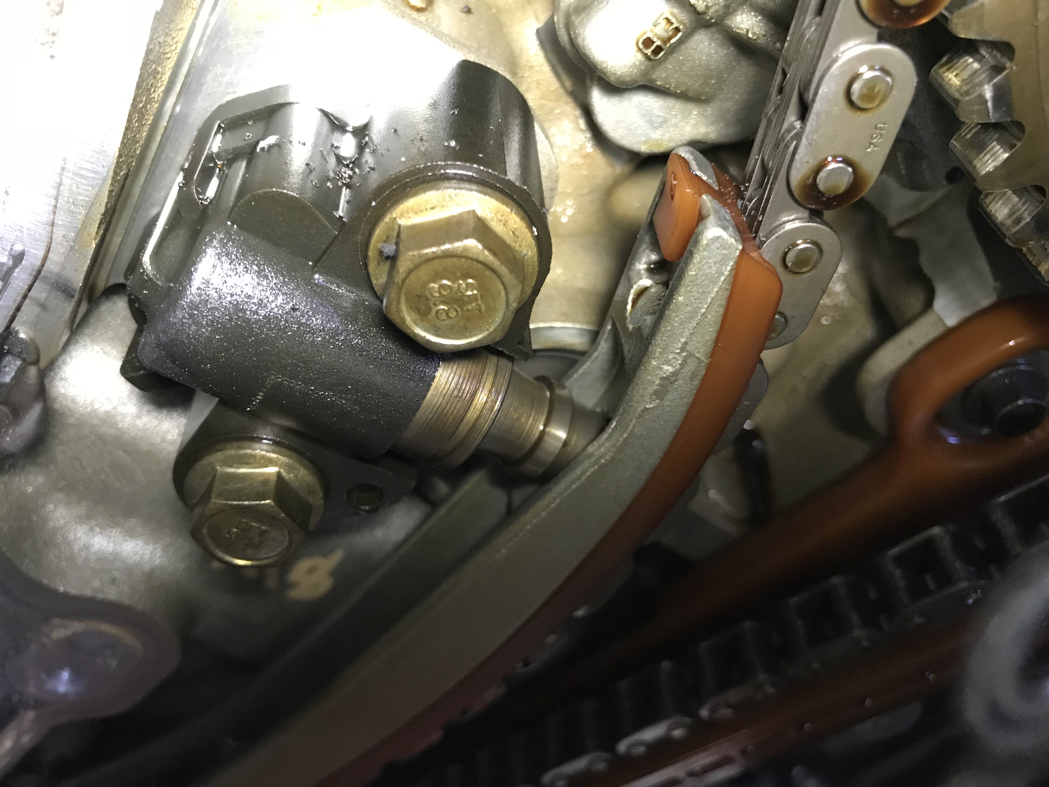
When we unbolted and removed the chain guides we found a surprise- not only had one of the guides worn through the plastic and down to the metal, but the tensioner had actually broken through the guide!
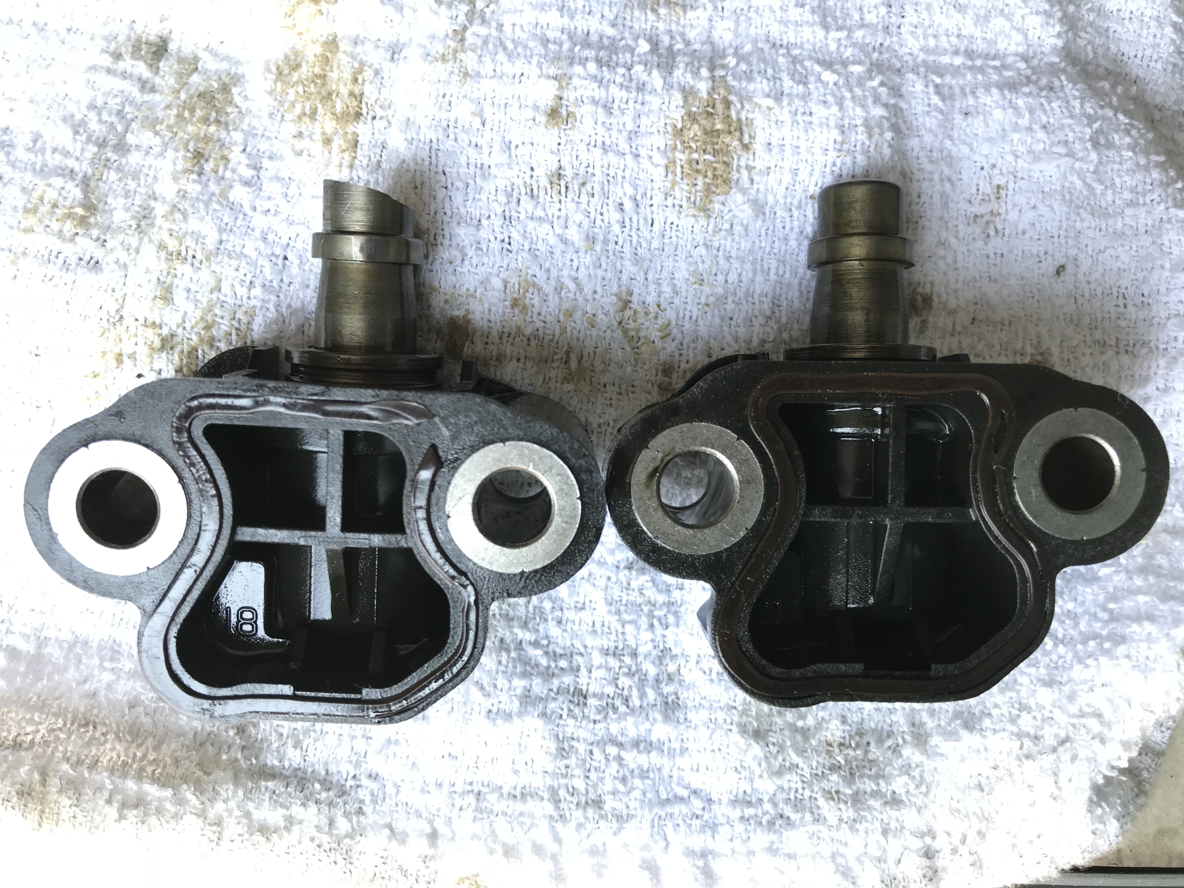
Two things to note here. One, the tensioner on the left was the one that broke through the guide and is missing a considerable amount of the head from the timing chain grinding it off. Less than ideal. Also note the gasket on the same tensioner vs. the one on the right. See that break up on the top right? That’s a common blowout and the cause of most chain rattles when cranking since these do not have a ratcheting mechanism and the loss of oil pressure allows the tensioner to bleed down.
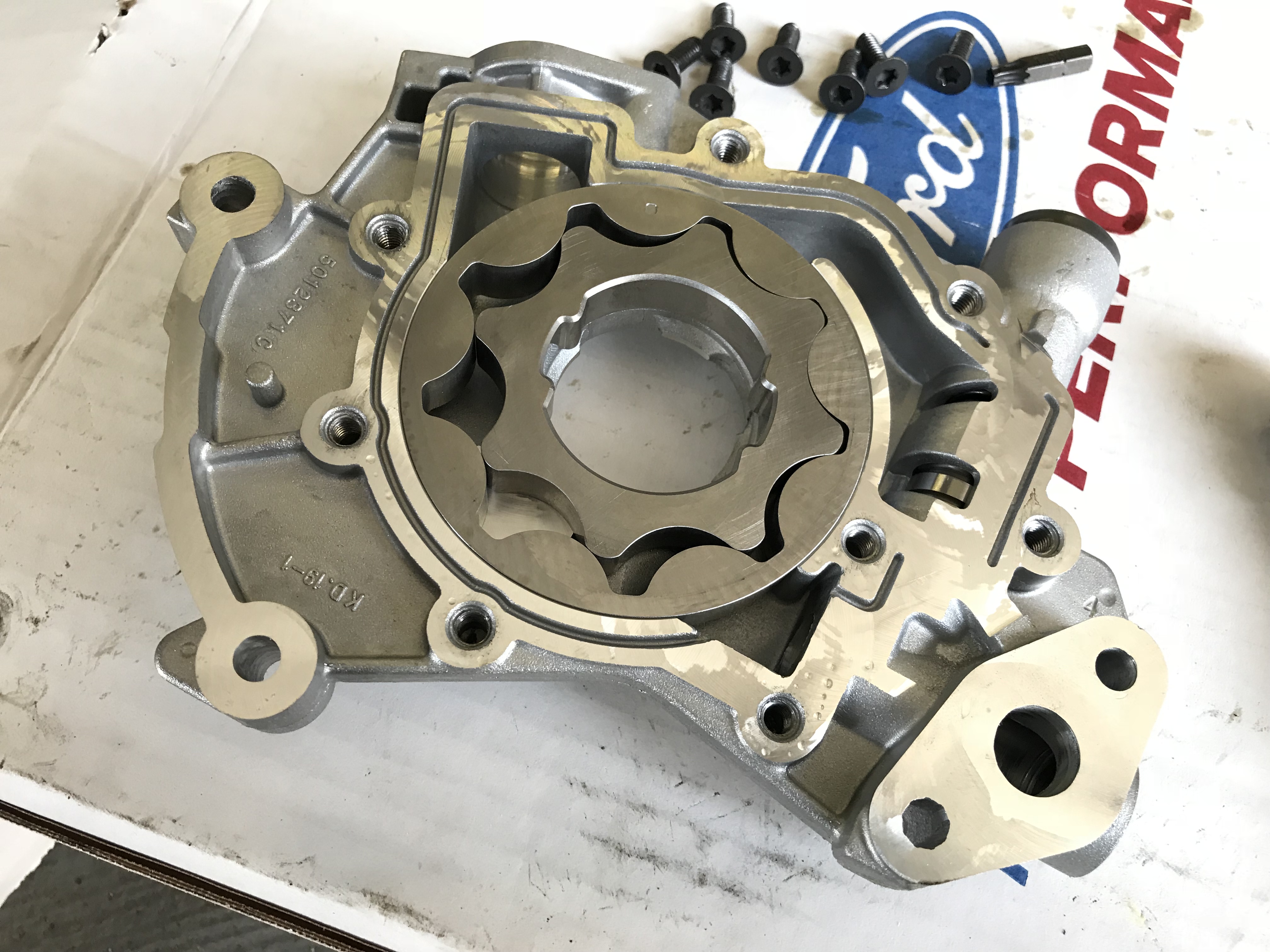
While we’re in here, we’re going to swap out the oil pump for a high volume unit from Ford Performance (PN M-6600-F46) since it’s a fairly simple and straight forward job.
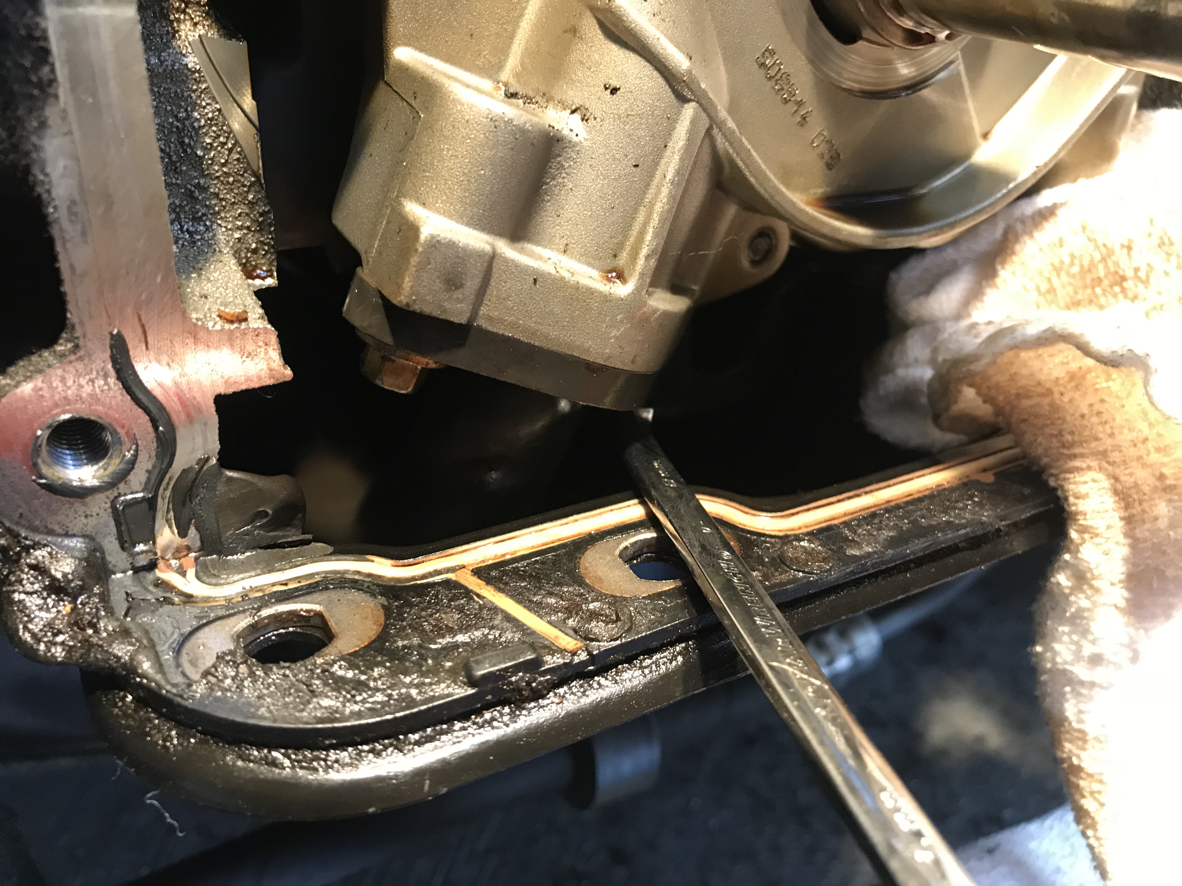
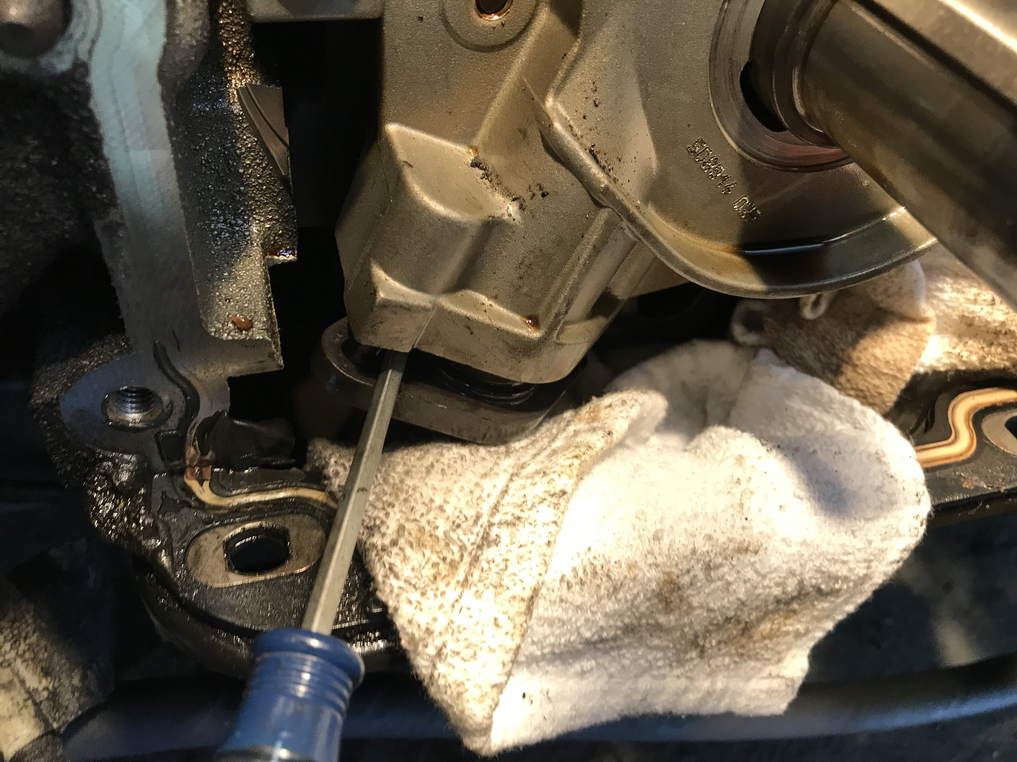
Since we are leaving the oil pan in place, the trickiest part of this is getting the pick-up bolts loose. An 8mm ratchet wrench is a must for this job. Also, keep your finger on the bolt or you’ll be fishing in the pan with a magnet.
With the mounting and pick-up bolts removed, use a screw driver to gently push the pick-up tube downward to remove it from the pump. The mounting bracket in the pan will hold it in place.
The Ford Performance pump is ready to go out of the box, but we popped the backing plate off to add a bit of oil to the gears to prime it.
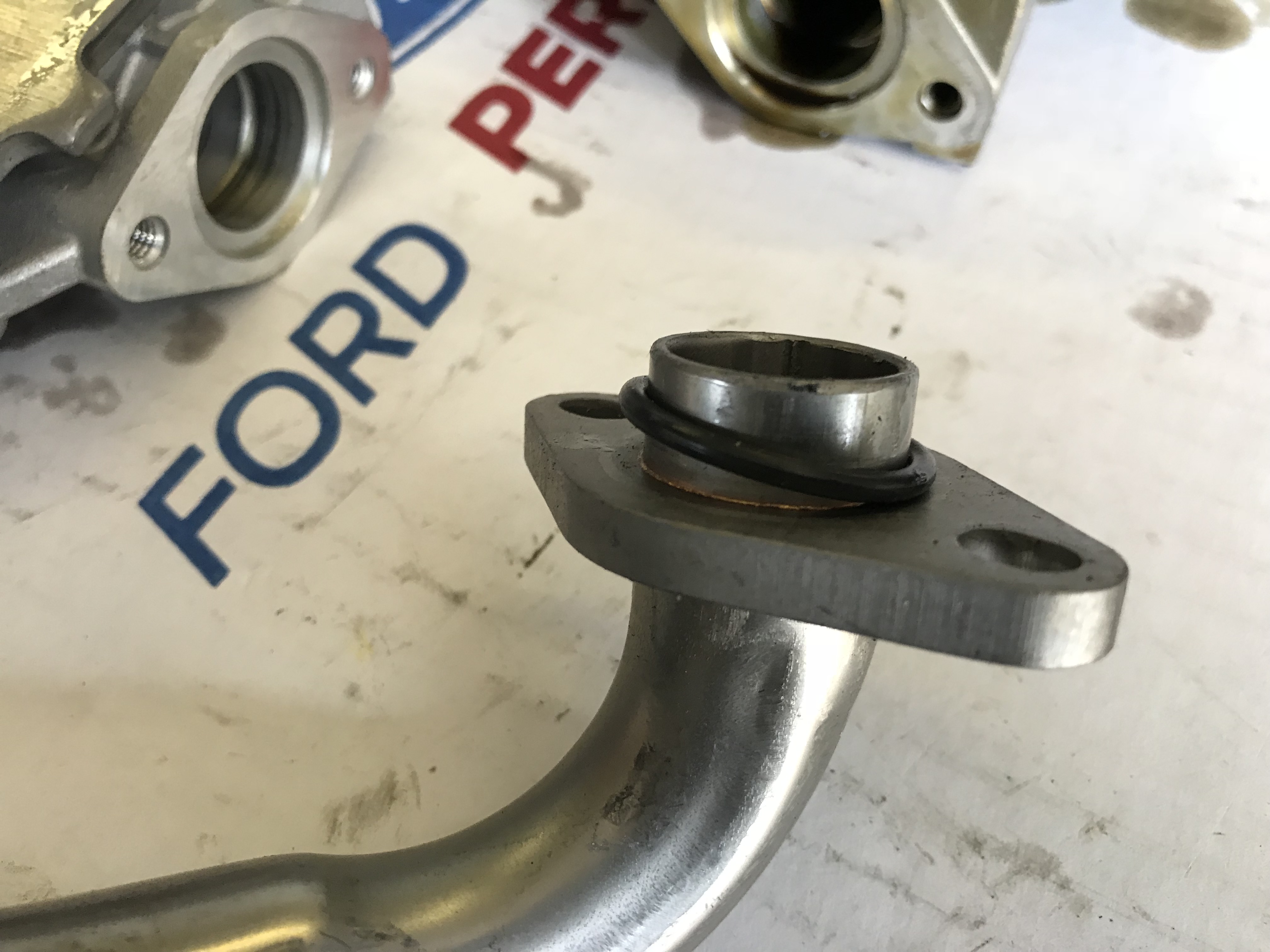
We won’t be using the new pick-up tube since that would require dropping the oil pan, but we will steal the new o-ring to swap onto the tube still in our pan.
It only takes a slight amount of wiggling to get the pump to slide right into place. Torque the mounting bolts to the correct spec and just get the pick-up tube bolts good and snug.
Now it’s time to pop off the cam phasers. This is another place where an impact will come in handy. To prevent cam movement, grab the phaser with a rag before you hit it with the impact. It’s not torqued tightly, so it should not put up any fight coming out.
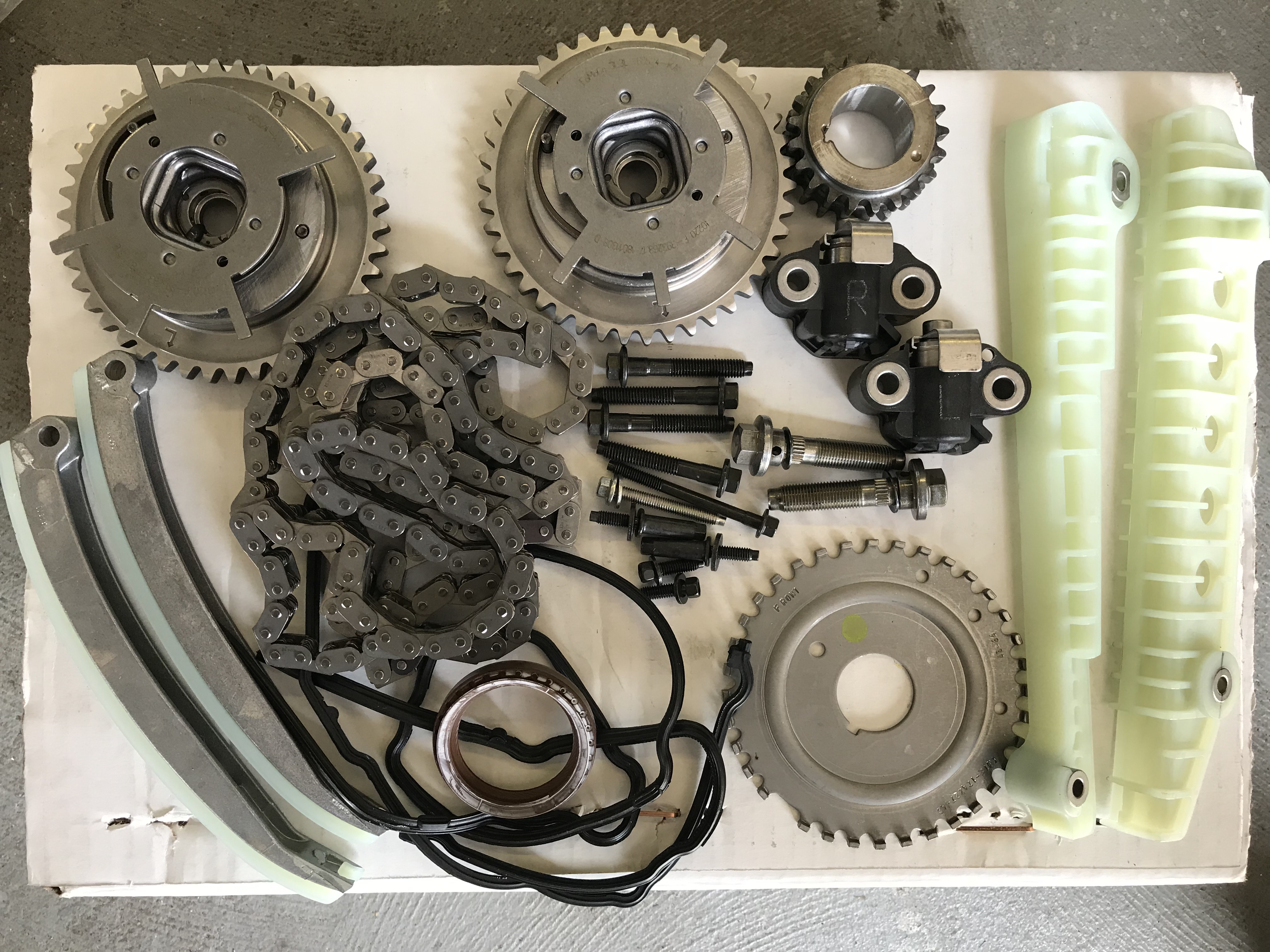
This is the savior of your 3V, the full timing replacement kit from FRPP (PN M-6004-463V). Not only do you get the critical timing components like the chains, guides, phasers, and tensioners, you also get all new gaskets, sprockets, seals, bolts, and even a reluctor wheel. This is by far the best kit on the market and Summit Racing features it for the best price we have found.
The chain guides are uniquely shaped and only fit one way, so there is little chance of installing them incorrectly. Also worth noting, you need a torque wrench that can convert to in-lb for proper torque spec on these bolts.
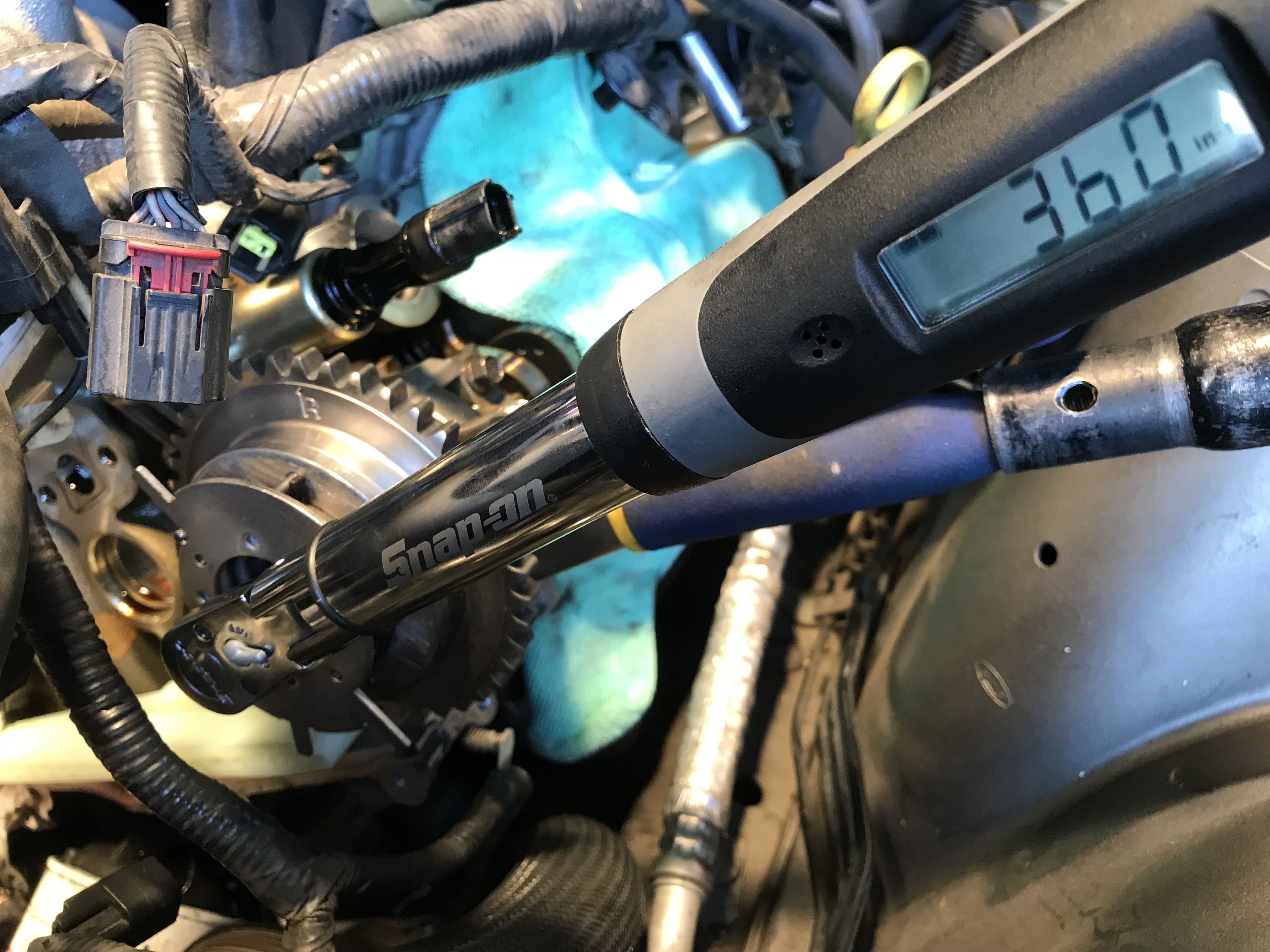
Unlike earlier kits, the FRPP cam phasers are identical, so there is no L & R. They slide onto a keyway on the cam, so there are also no worries about improper installation since we timed the engine before removing the stock stuff. These torque in two stages (Stage 1- torque to 30 ft.-lbs., Stage 2- tighten an additional 90 degrees) but just get them snug for now; we’ll torque them once the chain is holding them securely in place. Some are tempted to lock the phasers out, but trust us, on a mild, natural aspirated street car you’ll lose a lot in the midrange without them.
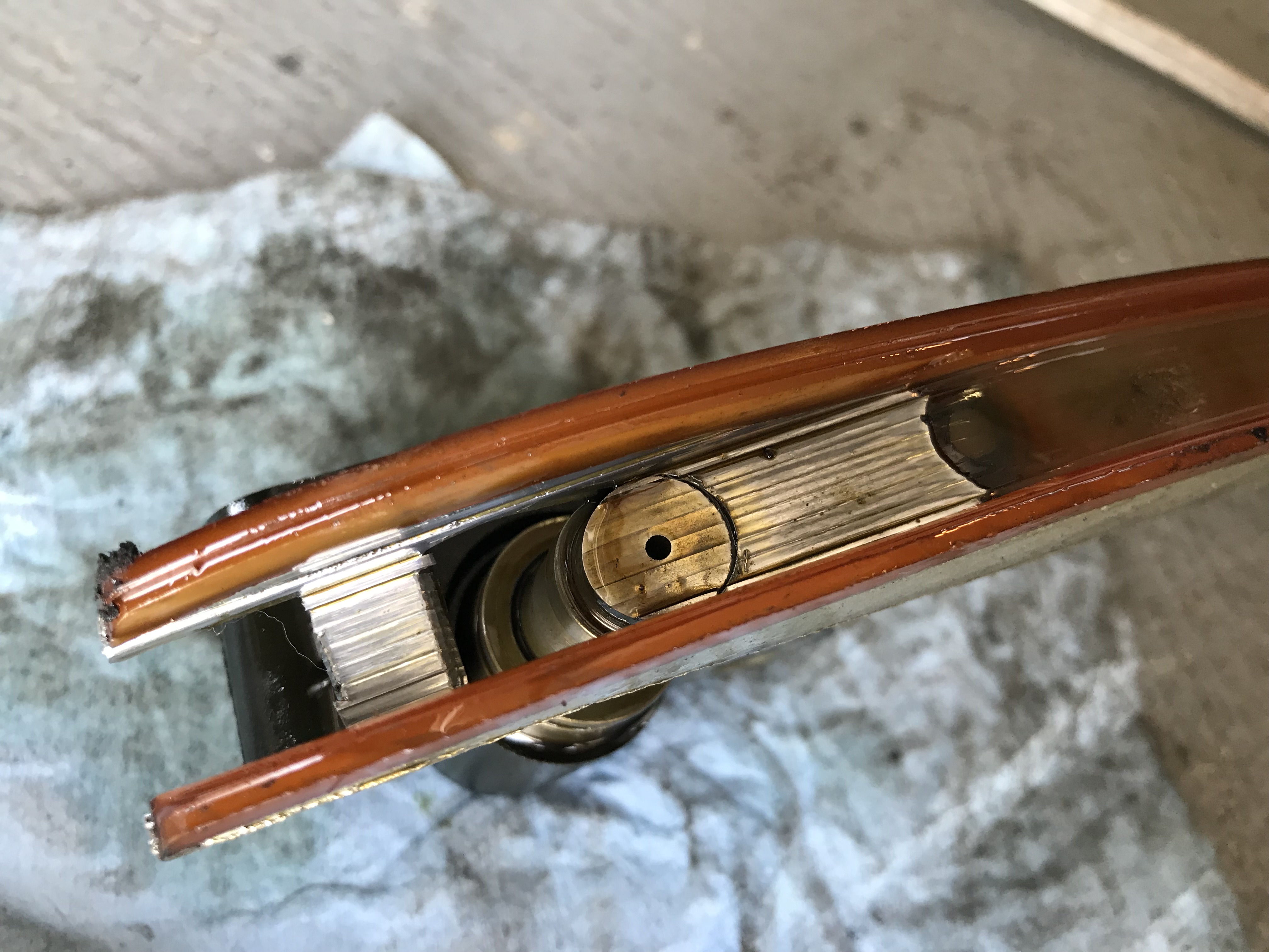
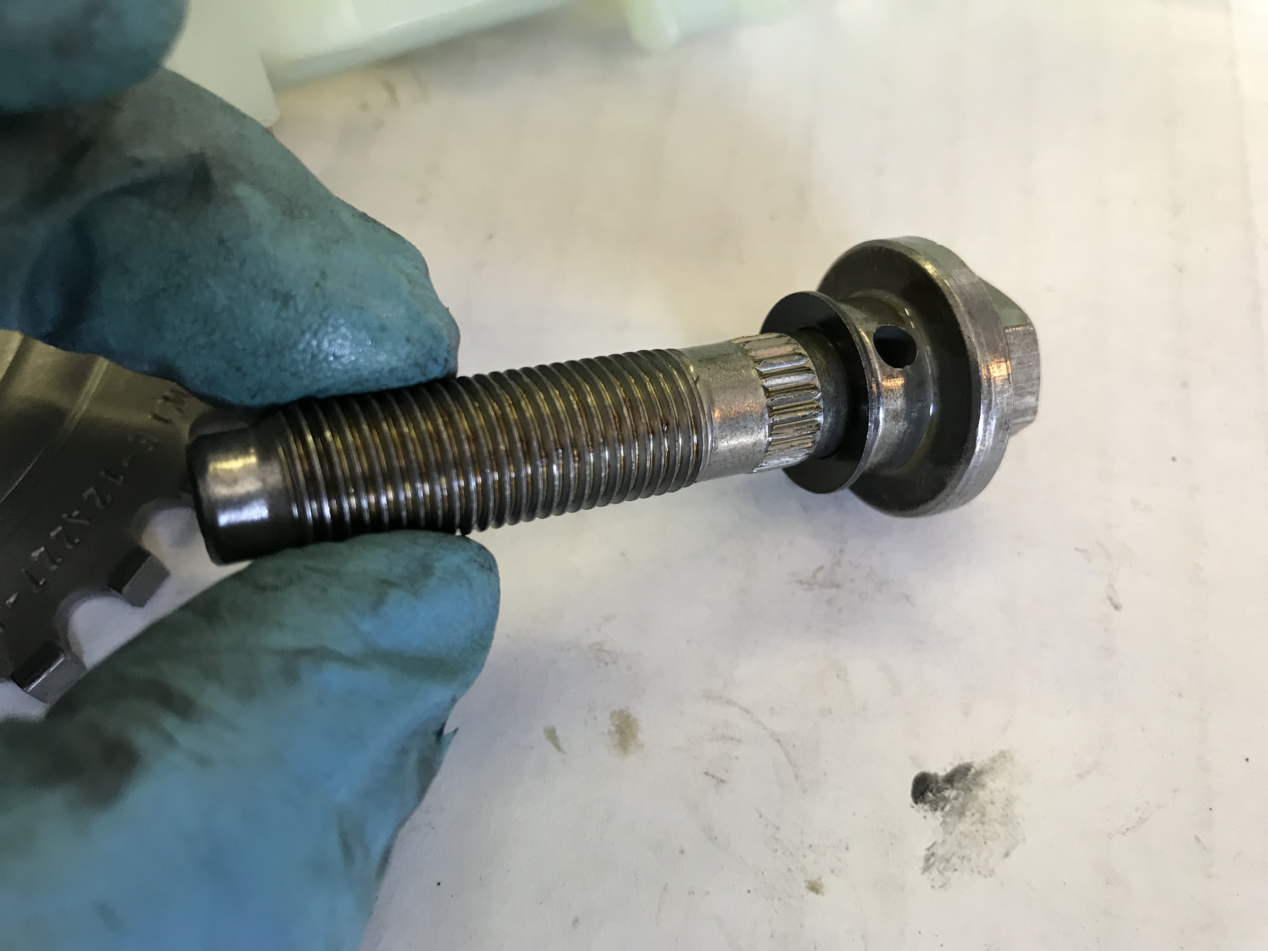
If you’ve ever wondered how those phasers get the pressurized oil to advance & retard the cams, take a look at the bolt, which happens to be hollow. That hole near the head is where it is directed into the phaser.
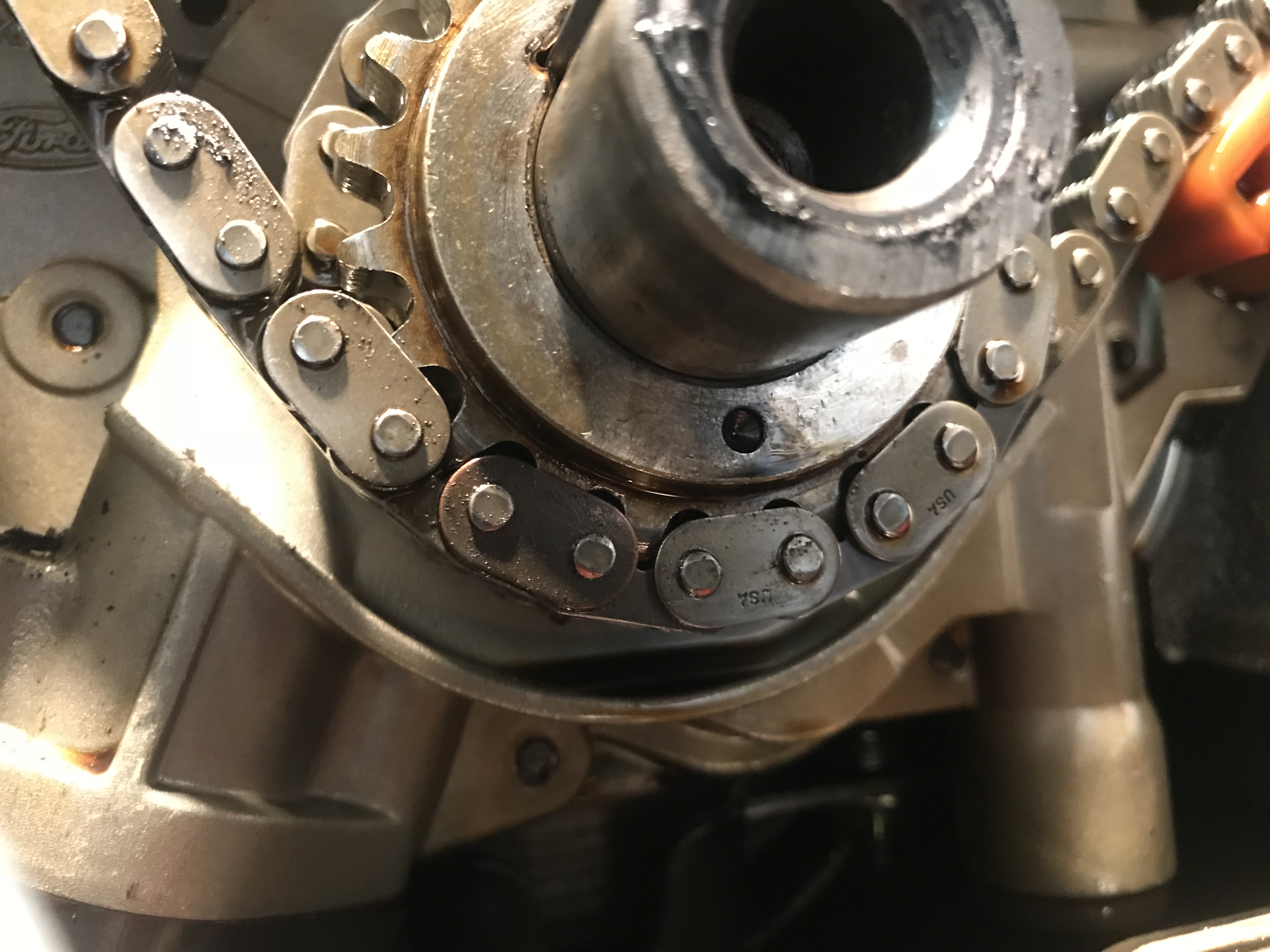
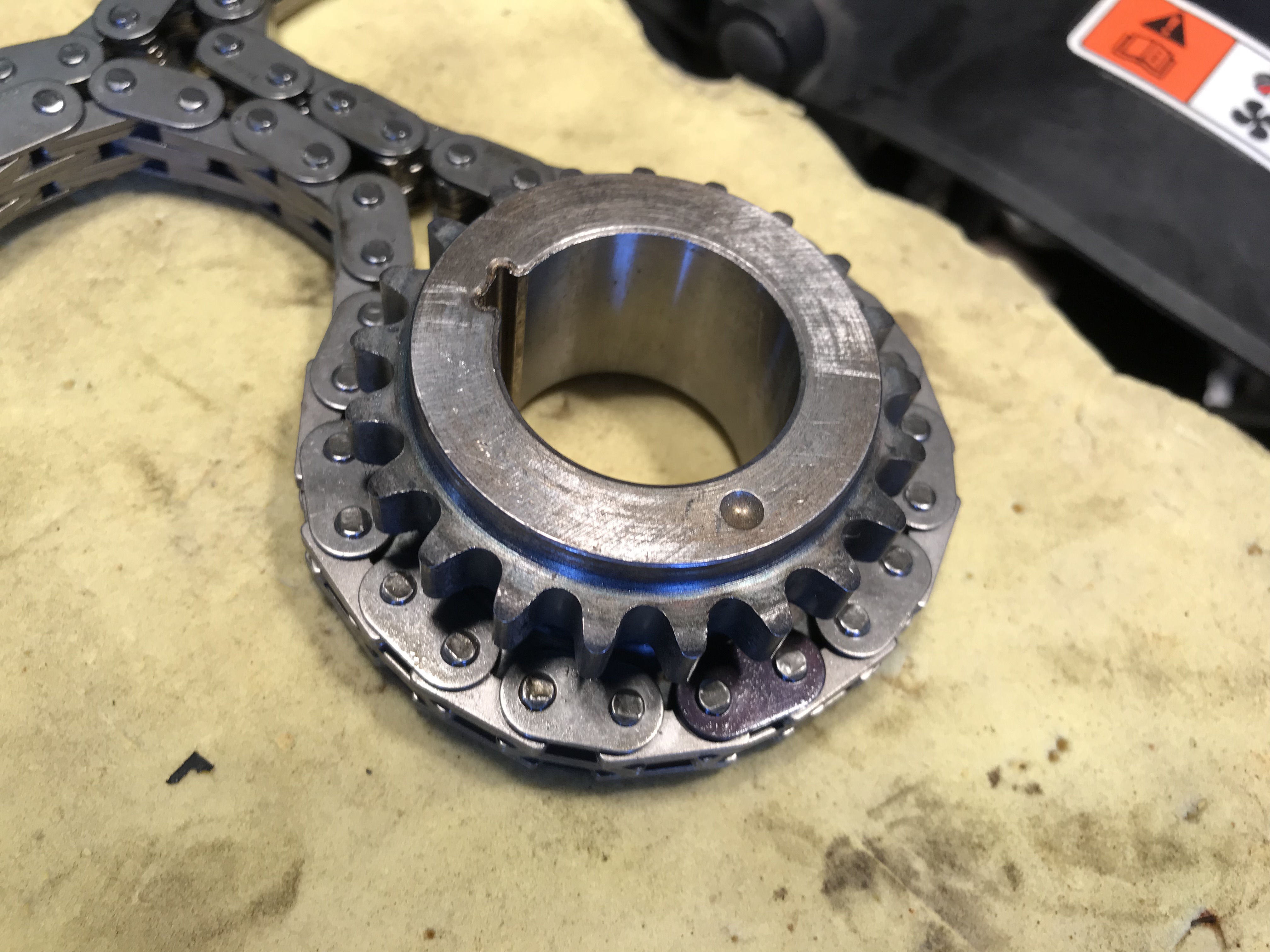
Chain time! Before anything goes on the engine, line up one of the dark links with the dot on the crank sprocket. The rear teeth will line up with the driver’s side bank of the engine.
Once you’ve slid the crank sprocket on the engine and looped the driver’s side chain around the phaser (there should be plenty of slack), add the passenger side chain. It’s good practice to visually verify that you see the dark links lined up on the dot for both chains with both chains installed on the phasers before moving forward. As long as the crank has not moved and the dot on the sprocket is pointing downward in the 6-o’clock position, we’re good on this end.
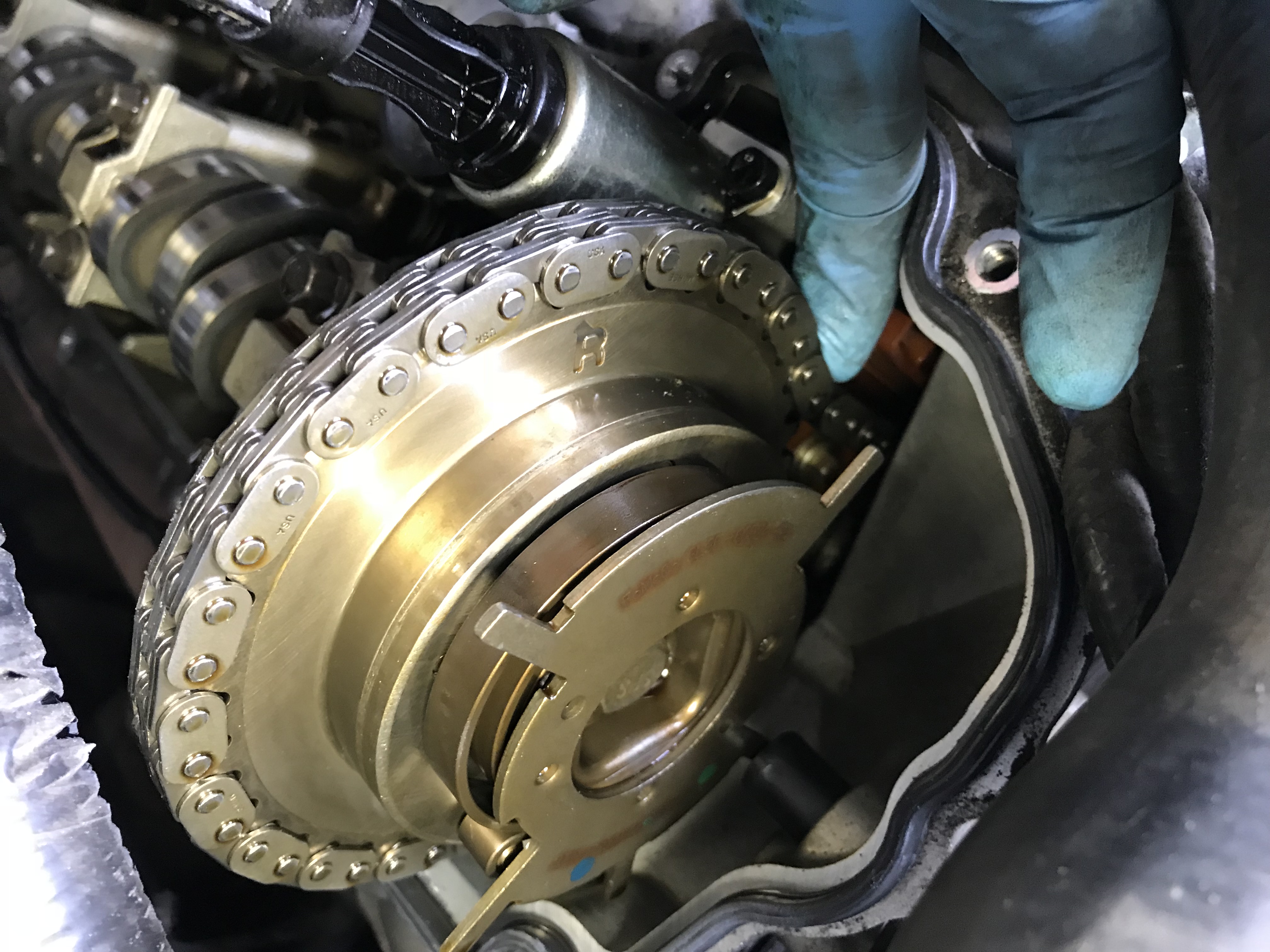
Remember what we said about the FRPP phasers being identical? That means they feature both the L & R marks, so it is critical to verify that your timing matches up to the right one. On the driver’s bank (L from the sitting in the driver’s seat), the second dark link should straddle the L mark.
Conversely, on the passenger bank, verify that the dark link straddles the R. If you see this alignment on both banks, and you have dark chain links straddling the dot on the crank sprocket (with the dot pointing downward at the 6’oclock position), and of course assuming nothing has rotated since removing the old timing chain, this is confirmation that your engine is timed correctly.
With cam timing finished, it’s time for the floating guides that the tensioners use to press against the chain. At this point, you may need to release the locking method of choice on the cams to allow some rotation to create the necessary slack.
These guides also only fit one way, but it’s a little less obvious. The floating guide on the passenger bank has this offset to space it out a bit since this bank has the forward mounted chain. The tensioners are also marked L & R in the kit to make sure the they are properly installed. Leave the lock in place until everything is torqued down properly (guides, cam phasers, etc).
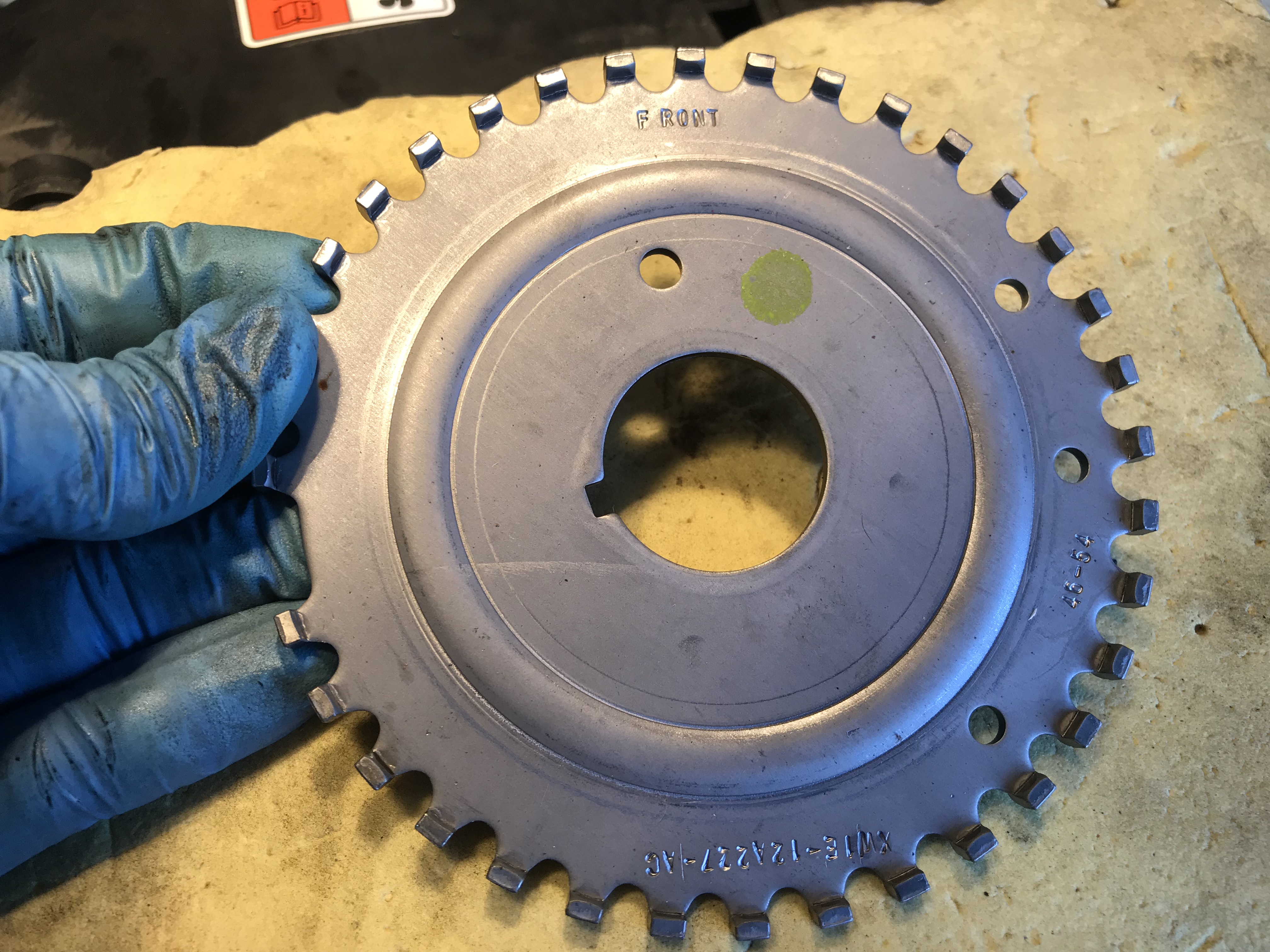
Reluctors don’t really wear out, but it is a good idea to install a fresh one with new and tight tolerances. The only thing to note here is make sure you slide it onto the crank with “Front” facing outward. It will not register on the crank sensor if it’s backwards.
Here we are with everything installed and torqued and the tensioners released. Now it’s time to prep the front cover to be reinstalled.
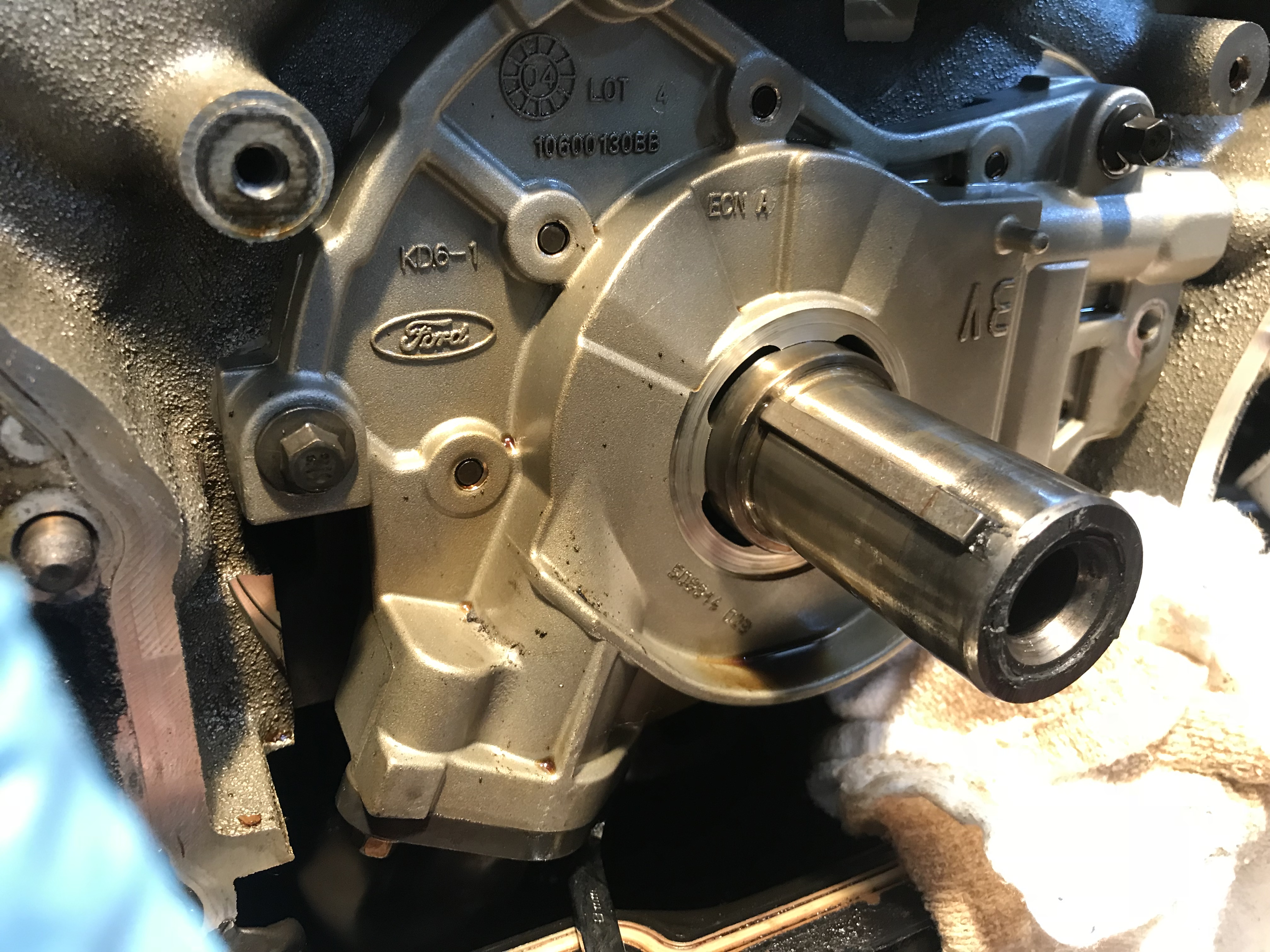
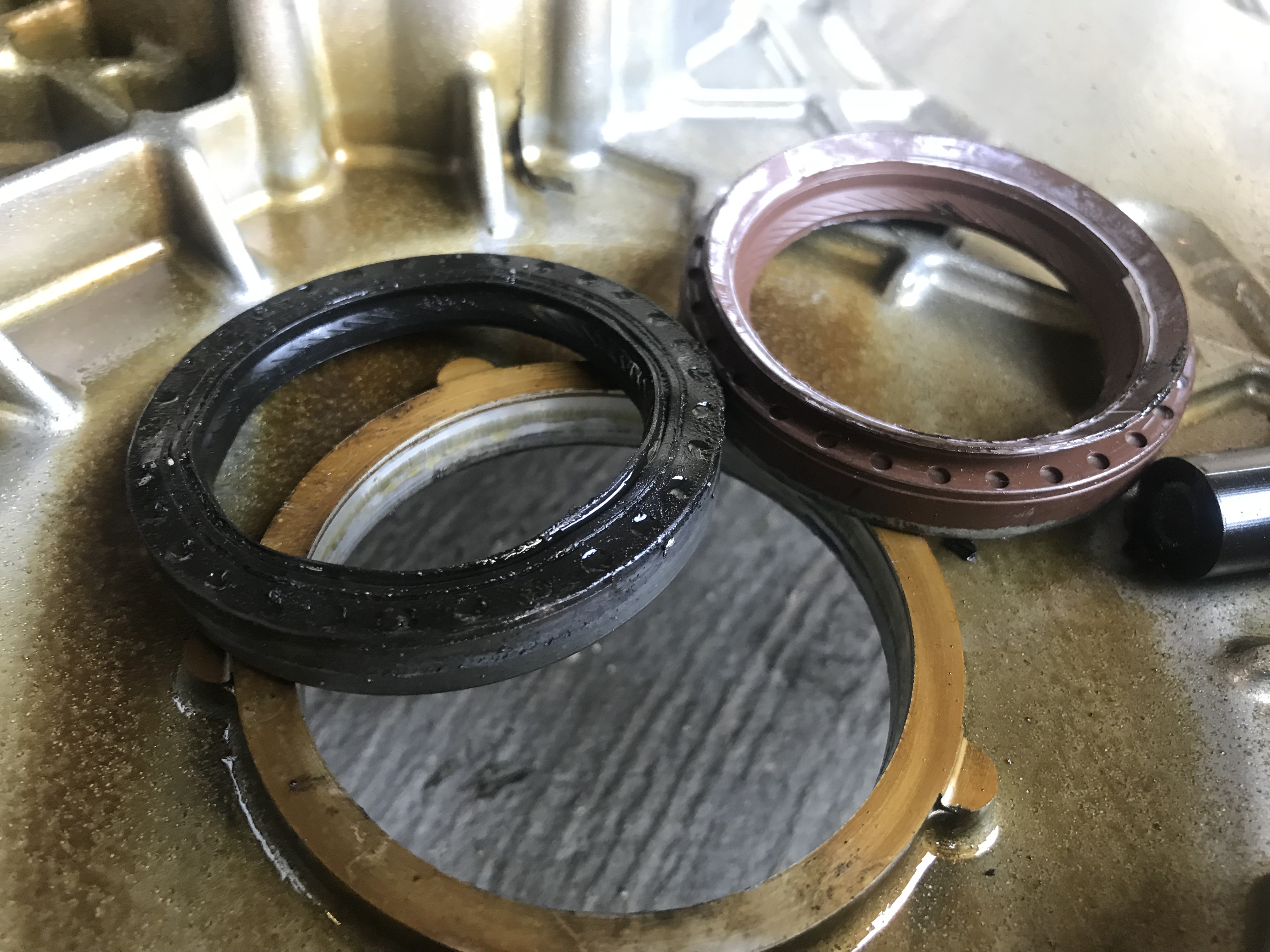
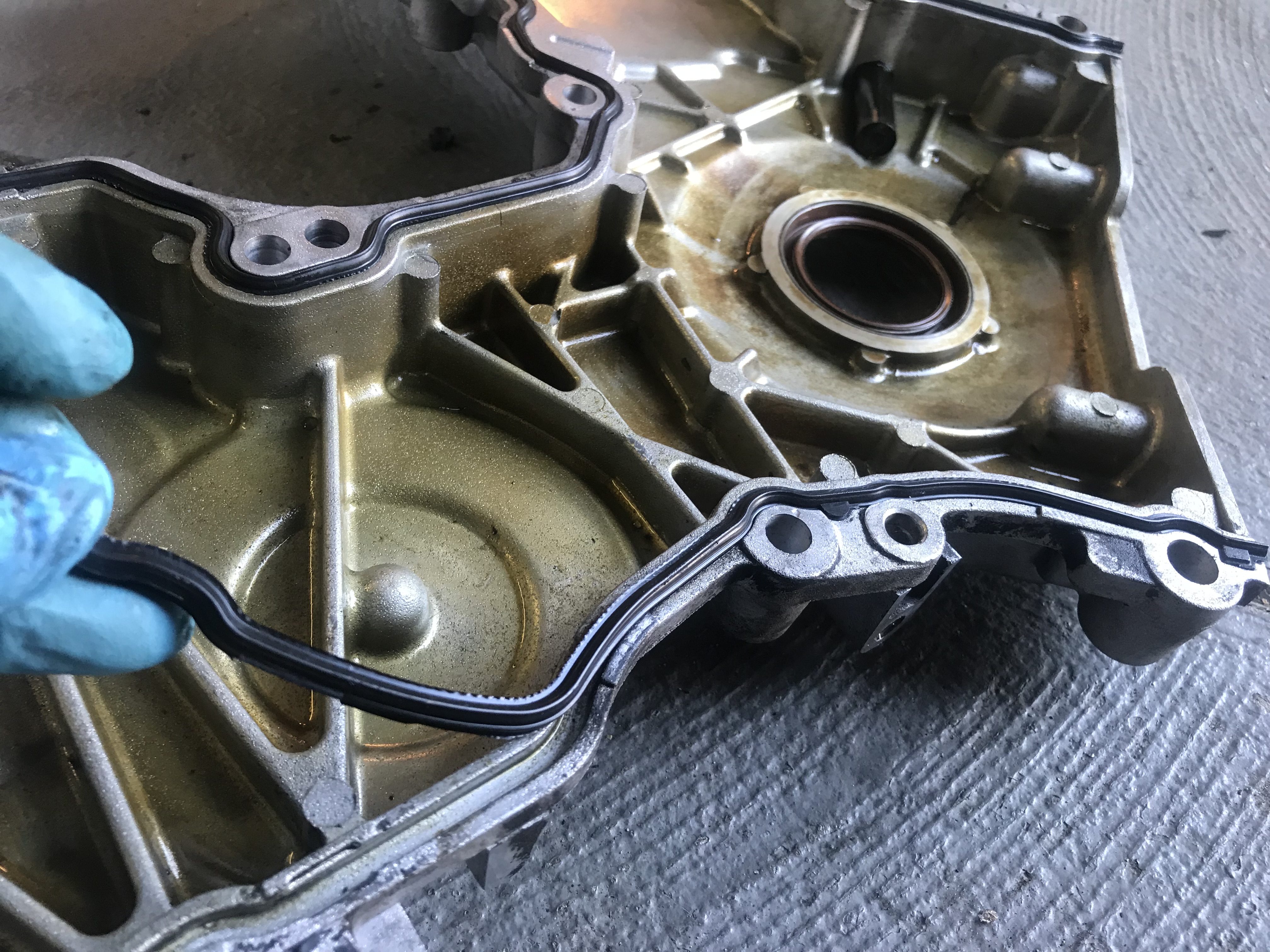
Remember that godawful mess behind our balancer on the front cover? That was from this guy; the front seal. These notoriously start leaking on 4.6’s around 75-100k. They’re a pain to remove with the cover still installed, but quite easy to tap out with a large socket or seal press with it removed. As you can see here, the oil lip on ours was gone. The new seal will tap in with a rubber mallet.
The FRPP kit also includes new front cover seals to keep everything nice and sealed up. There are three unique pieces and they are specific to their side. Use the square tabs at the ends to easily determine which seal is which. All the cover bolts torque to 19 ft-lb, but there is specific sequence recommended by Ford available in the document linked in the text body.
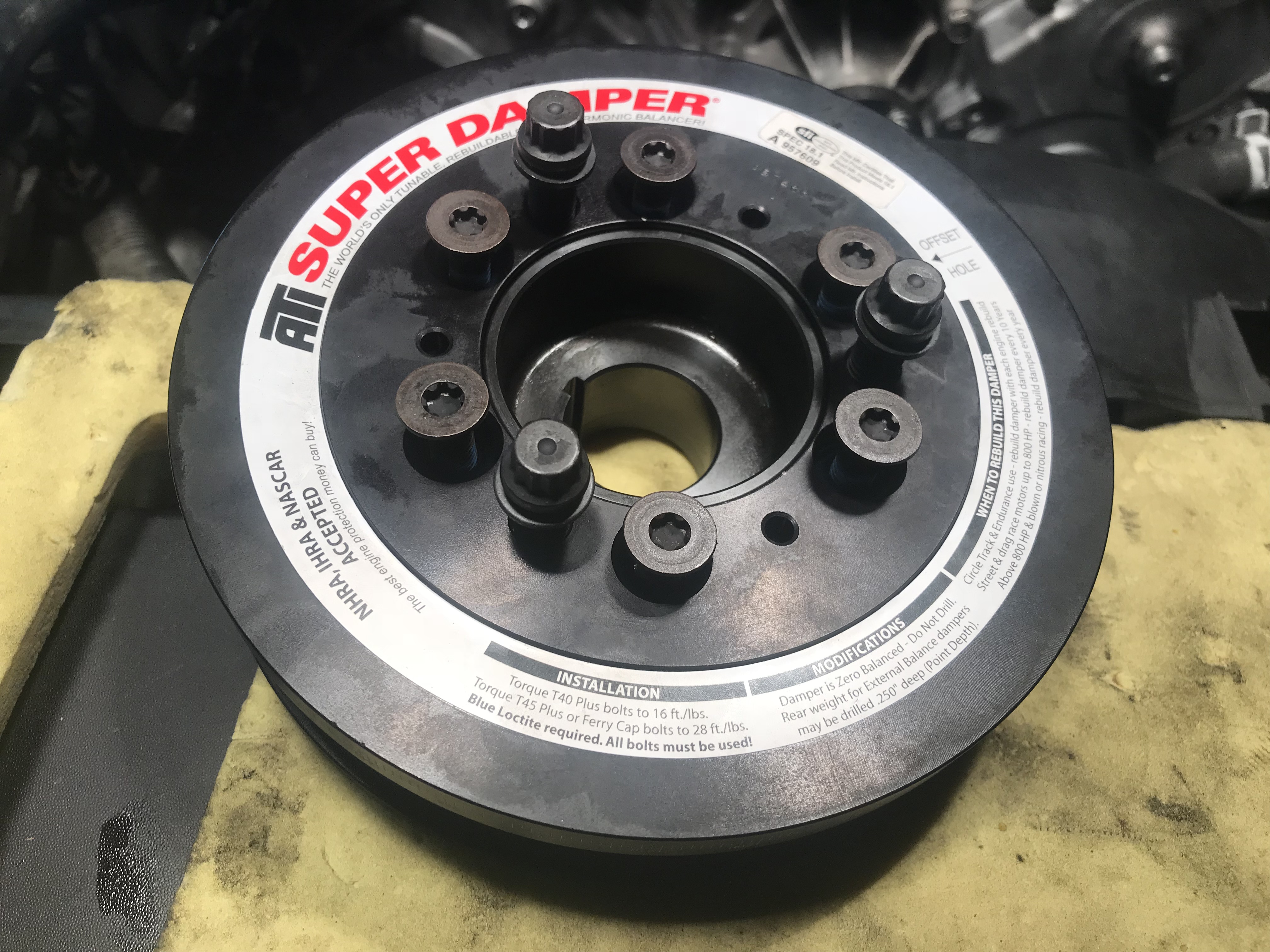
Since our project gets tracked occasionally, and since our factory balancer was high mileage, we splurged a bit and treated our 3V to an ATI Super Balancer. These come with a little assembly required. All of these bolts require a touch of blue thread locker and must be torqued to the specs on the balancer itself.
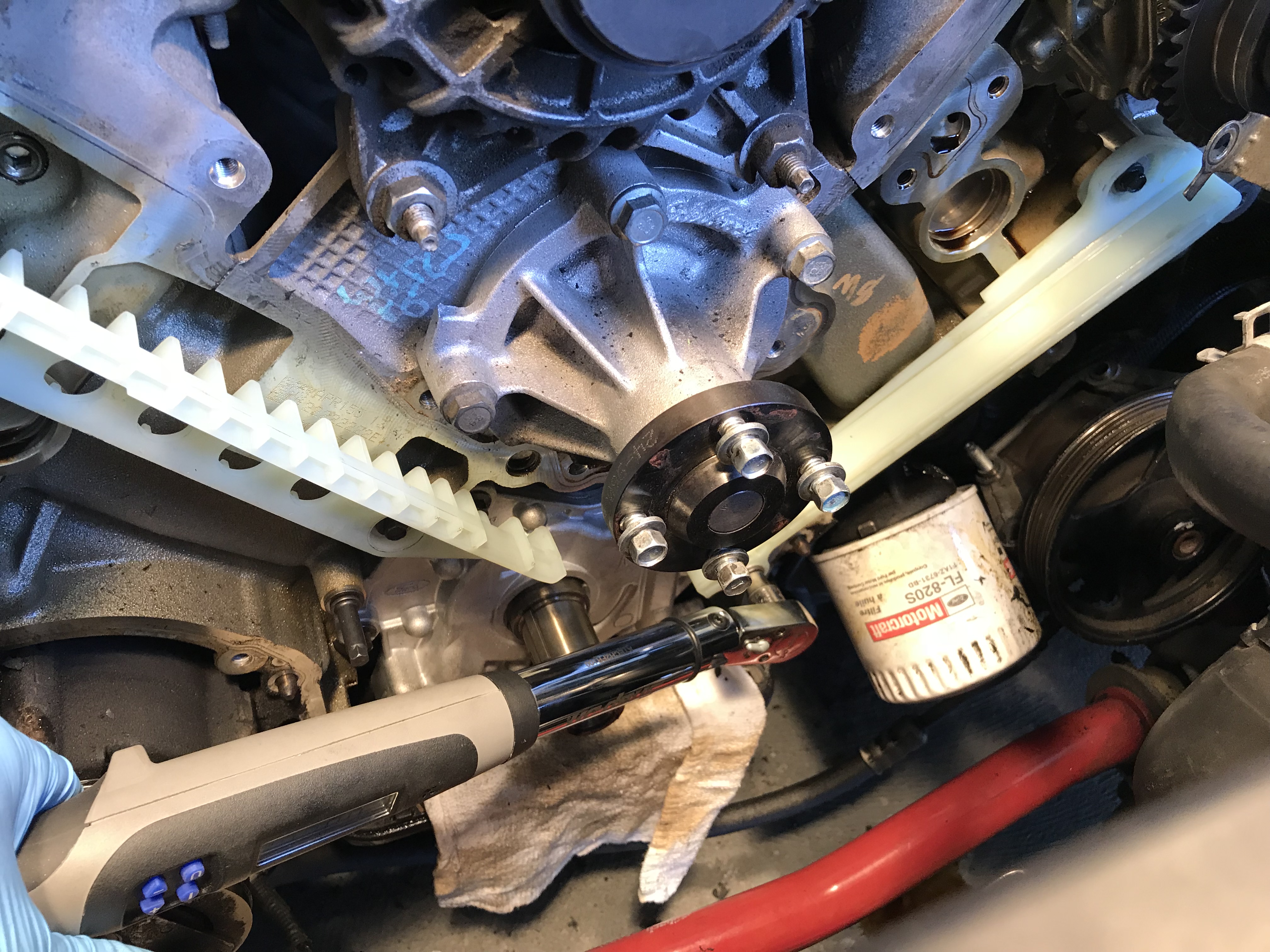
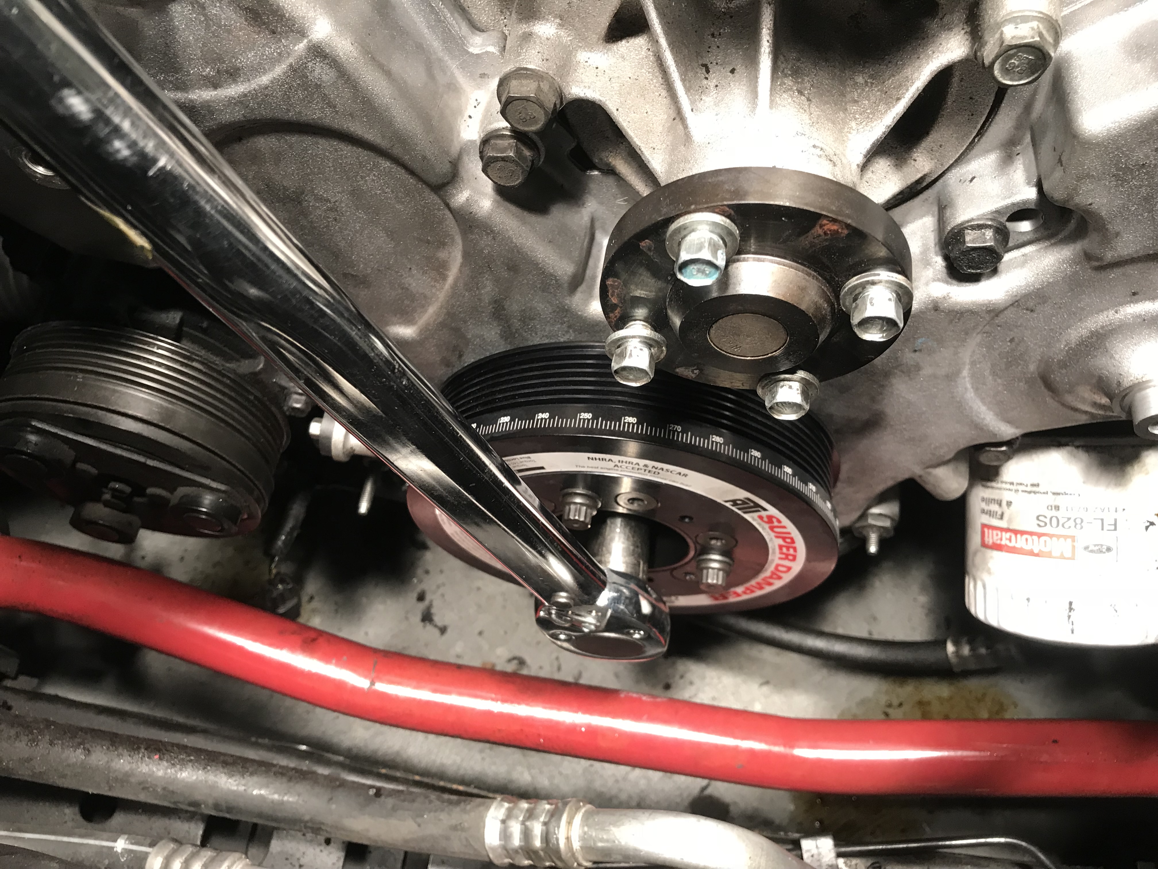
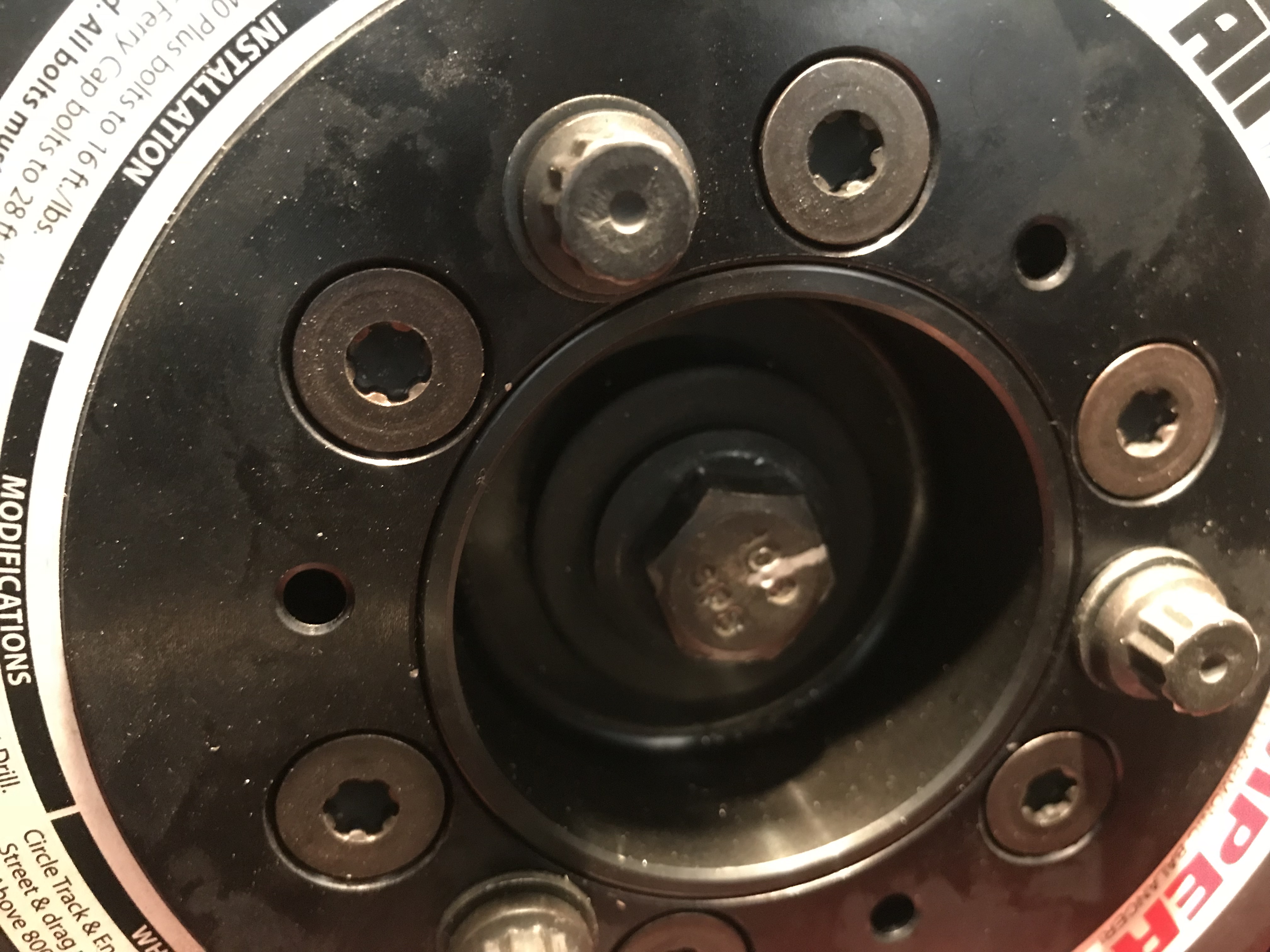
For 4.6 engines, there is a washer that must be slid on the crank prior to installing the balancer for correct offset. Don’t forget this, or you’ll be pulling the balancer back off- and buying a new bolt since they are single use torque-to-yield. The torque sequence for the crank bolt is tighten to 66 ft-lb, loosen 360 degrees. Then tighten to 36 ft-lb and then and then additional 90 degrees.
That last part of the torque sequence is critical, and it can be difficult to determine if you got a true 90 degrees with the engine in the car. The easiest way to monitor the progress is to mark the bolt head and the balancer with the starting point and also mark the balancer with the end point you need to hit. We’re not sure how much torque this requires, but you may need a goo long breaker bar.
That last part of the torque sequence is critical, and it can be difficult to determine if you got a true 90 degrees with the engine in the car. The easiest way to monitor the progress is to mark the bolt head and the balancer with the starting point and also mark the balancer with the end point you need to hit. We’re not sure how much torque this requires, but you may need a goo long breaker bar.
Though not always necessary, we did find in our case that the VCT solenoids (PN 917-200) were getting weak and needed to be replaced. Since the valve covers are a bit of pain to remove, it’s not a bad idea to replace these while you’re in there. Just one Allen head screw holds them in place. We also recommend replacing the valve cover gaskets (PN VS50372) while they’re off, and they do have a recommended torque sequence that is available in the doc linked in the text body.
Once you’ve got the accessories and air intake back on, you’re ready for a first crank! Our engine was immediately much quieter and smoother sounding and no more crank rattle. Assuming everything was done correctly, you shouldn’t have to think about any of this stuff for another 100k or more.
Christopher Campbell has been heavily involved in the automotive world since he began building his first car, a 1967 Ford Ranchero, with his dad at the age of 14. That started a lifelong passion with custom hot rods and muscle cars. After graduating from Cal State Long Beach, he went to work for HOT ROD magazine as Associate Editor. From there he became Technical Editor at Popular Hot Rodding magazine. Currently he creates freelance content for OnAllCylinders as well as many diverse enthusiast magazine titles such as HOT ROD, Muscle Mustangs and Fast Fords, Mopar Muscle, Super Chevy, Mustang Monthly, and 8-Lug.
Comments
44 responses to “How to Change the Timing Assembly on a Ford 4.6L 3V”
When we replace the chain tensioners on the dohc Australian falcon 5.4lt engine we upgrade the plastic body type with genuine Ford cast iron units. They don’t warp and blow the seal out. Maybe just a thought.
Hi Jason,
This method works fine as well, but the new design tensioners included in the 3V timing kit from Ford Racing will not suffer the same failures as the original design. If you need to update everything, this kit will get you in good shape without spending extra.
Thanks for the write up! I have a P0012 cam timing bank 1 over retarded code. (after hot rod install) Im assuming it skipped a tooth or something. I pulled valve cover off and found slack in passenger side timing chain only when crank was rotated counter clockwise. It was tight when rotating clockwise. Is that normal? I noticed some slack on the picture you took when timing chain was put back together. I ordered the whole timing chain kit and plan on installing that but i want to see if that was normal or not. Thank you.
Hi Andrew,
Slack in the timing chain is a not a normal condition on these engines (or really any engine) if all components are in good condition. It should remain tight no matter which way you rotate it. It sounds like you likely have a failed tensioner, possibly with some additional wear or damage to the guides. This kit should fix you right up. Just be patient with the process, mind your cam timing, and you should be fine.
Nice write-up! This beats all the YouTube videos I’ve watched, as well as the shop manual I just purchased. I’m getting ready to do the timing set and oil pump as maintenance items on my ’06 GT with 125k and this will help immensely. Thank You!
Ive having a issue timing my engine. how should the cam lobes be facing when in time.I took the old chains and tensioners off before verfying tdc like an idiot. now Im chasing my tail and want to be sure its at tdc. also so im clear, standing in front of the car looking at the engine my right side uses the L mark on cam phaser and my left hand uses the R mark correct? also the cam phasers can not be installed on the cams in anyway backwards Im assuming. just verifying its my first 3 valve engine
Thank you much for these great instructions. Followed these, along with the oil priming advice from YouTube videos, for a successful first-time job on a 2008 Mustang GT;ordered the entire parts kit from Summit. I did choose to remove the fan for a bit more working room. No more P0016. Due to a previous crack, did manage to break a boss off of the timing cover, so now I have a new cover too.
Hi sir in april 2008 you wrote an article about a 2v 4.6 that you carburated and put the mod 6 on I myself built a similar motor a 96 non pi block with 03 heads .30 over with stage 2 comp cams springs and retainers and adjustable cam phasers shorty heads also like yall had done im also running edlebrock intake 650 double pumper with 67 and 77 jets and I seen you had 32 degrees of timing at 3000 rpm what was the initial timing and advanced map curve if you dont mind me asking only difference in our motors is you had ur heads cnc ported and mine are not seems nobody has this information and to run so many test on the dyno is just so expensive
Hi i have an 05 mustang gt 4.6 200,000 miles on it. i have the timing cover off and ready for phaser lockouts but the phasers do not have an R on them i did find an L on both of them and also a short line on both of them as well. is this short line representing the R?
I have an 09 F150 with a 4.6. I wonder if there is any reason to increase the performance. I have a 36’ camper that I tow regularly. I am going to do timing complete, however can I get a cam designed for towing?? The truck has pretty great power. But up hills with a 9300# camper can slow it down a bit. Thanks.
Hey Mark,
There aren’t any cams for the 3V that I am aware of that will dramatically increase your torque and low-end power over stock. A cold air kit and a tune are your best bets. Beyond that, supercharging is an option. If you tow a lot, you might also consider a higher gear ratio (4.10, etc)
Can the timing, (phasers and chain being bad) make my trick skip under load??? I am scared to death to do plugs. Since I know how they are to get out without wrecking the threads or breaking them off. Any info would be helpful. Thank you.
Hey Mark, apologies for the late reply. It could, but you would be getting codes thrown at by now.
Plugs are not as scary as they might seem. Follow the Ford tech procedure and you will probably be fine. Worst case, an extraction tool is available and works well (Lisle 65700).
So the timing chain tensioner gasket is slightly lifted on one corner on one of my new tensioners but not torn. Would that effect its operation in anyway? Would oil bleed out of that area?
Hi Rey, it’s probably fine it is not torn. You can be extra cautious and run a VERY THING smear of a product like Permetex Right Stuff gasket maker around it.
I have a 2005 Mustang GT with 125K miles and was experiencing the 2-3 second rattle at startup but about a week ago it starting rattling much longer but only after leaving the car sit overnight and in warmer temperatures. I guess it sounds like it’s time to perform this procedure. Since it just started doing this, about how much time do I have before it gets to be really critical to get this done?
Hi Terrell,
I see you posted this in March, did you already handle the timing kit?
If not, I would recommend doing so soon. The 2-3 second rattle at start-up is your warning that there is a timing chain issue. When it starts going for longer, the issue has gotten significantly worse and it’s a ticking time bomb before a large failure. Good luck!
After putting the timing chain on a V8 three valve V8 engine is it a good idea to rotate the engine a few times and I noticed the timing marks don’t line up I don’t know how many times it has to be rotated
Alan,
Because the crank and cam sprockets are different diameters (for speed purposes), once you rotate the engine, it takes several revolutions to get everything back in sync. It will eventually line back up if everything was installed correctly.
hi everyone and sorry for the stupid question. When aligning the phasers before disassembling the old chains, is it necessary that the colored part of each chain is perfectly aligned or that it is close to the indicators as in the pictures?
Thanks in advance.
Hi Matteo,
Not a stupid question at all. Yes, you want to perfectly align all three timing marks (cam sprockets and crank) to the darker link on the chain before removing the original chain. It is possible to time the engine without doing so, but it is a much more involved process.
I couldn’t time my 4.6. one of my valves was bent on the number one cylinder. I took my heads and camshafts out together. I took the cams out and had the head’s redone. When I put my heads back on and then I put the cams back on, how do I know if I’m on the compression stroke so I don’t cause the combustion to go in wrong direction? With the heads off I can see my pistons and cylinder one is at TDC.
Hey Chris,
Apologies for the delay in response, this came through while I was on vacation and I missed it. You can use the same timing procedure as above once you have the cams aligned. Start with the crank in the position shown above, with the dot facing downward at 6 o’clock. From there, you just need to get the cams in the right position.
Just did the chain kit on 2007 explorer 4.6 3v and there was no washer behind the balancer. I see in your video it says there is a washer. Just thinking that the cover was removed before and they forgot the washer or if it is not required on this year.
Chris,
I have a 2010 Mustang GT, 4.6 obviously, and I about to redue my timing components but noticed that on both the right and left bank the dark link was one link off from the phaser markings. Is that a normal thing or did the factory install the timing components incorrectly? The car runs and drives, 192,000 miles and counting but I was hesitant to do the work with out first getting clarification. I need some insite on this!
Hi Ron,
Your engine just needs to be rotated over a few times all the dark links line up. Being one tooth off would result in constant misfire codes and limp mode under hard acceleration.
Before moving forward, both cam phaser marks should line up with the dark links, and the crank sprocket should also line up with two dark links when it is in the 6 o’clock position.
Hey, I have a 2006 mustang gt and I installed some hot rods cams about 2 months ago. About a week ago I notified a very faint rattle sound coming from the passenger side of the motor every 10 seconds or so. The car ran fine. Then all of a sudden a couple days ago, I got a P0011 code (“camshaft position timing over advanced bank one”). But the car still ran fine. I pulled the valve cover and it seems none of the timing marks line up at all even after spinning the motor multiple times to negate the diameter difference between the crank and cam, which makes no sense because the car was not misfiring at all… what do I do??? What could this be??

When we replace the chain tensioners on the dohc Australian falcon 5.4lt engine we upgrade the plastic body type with genuine Ford cast iron units. They don’t warp and blow the seal out. Maybe just a thought.
Hi Jason,
This method works fine as well, but the new design tensioners included in the 3V timing kit from Ford Racing will not suffer the same failures as the original design. If you need to update everything, this kit will get you in good shape without spending extra.
As a retired Ford mechanic this is well written and accurate. Good job
Hi Harlan, thanks very much, I appreciate hearing that from an experienced technician 🙂
Is this the same procedure for the 5.4 3v. Thanks
Hi Craig, yes, the procedure is identical.
Thanks for the write up! I have a P0012 cam timing bank 1 over retarded code. (after hot rod install) Im assuming it skipped a tooth or something. I pulled valve cover off and found slack in passenger side timing chain only when crank was rotated counter clockwise. It was tight when rotating clockwise. Is that normal? I noticed some slack on the picture you took when timing chain was put back together. I ordered the whole timing chain kit and plan on installing that but i want to see if that was normal or not. Thank you.
Hi Andrew,
Slack in the timing chain is a not a normal condition on these engines (or really any engine) if all components are in good condition. It should remain tight no matter which way you rotate it. It sounds like you likely have a failed tensioner, possibly with some additional wear or damage to the guides. This kit should fix you right up. Just be patient with the process, mind your cam timing, and you should be fine.
Oil has to pump up the tensioers to put pressure back on the timing chain!i went tho this with my cam install
Nice write-up! This beats all the YouTube videos I’ve watched, as well as the shop manual I just purchased. I’m getting ready to do the timing set and oil pump as maintenance items on my ’06 GT with 125k and this will help immensely. Thank You!
Don’t forget to put a dab of RTV black in the keyway on your factory crank balancer or you’ll have a leaky mess worse than a worn crank seal.
Hey Gary, absolutely correct
Ive having a issue timing my engine. how should the cam lobes be facing when in time.I took the old chains and tensioners off before verfying tdc like an idiot. now Im chasing my tail and want to be sure its at tdc. also so im clear, standing in front of the car looking at the engine my right side uses the L mark on cam phaser and my left hand uses the R mark correct? also the cam phasers can not be installed on the cams in anyway backwards Im assuming. just verifying its my first 3 valve engine
you get it figured out
If you are that unsure you may want to pay attention closer.
Thank you much for these great instructions. Followed these, along with the oil priming advice from YouTube videos, for a successful first-time job on a 2008 Mustang GT;ordered the entire parts kit from Summit. I did choose to remove the fan for a bit more working room. No more P0016. Due to a previous crack, did manage to break a boss off of the timing cover, so now I have a new cover too.
Hi sir in april 2008 you wrote an article about a 2v 4.6 that you carburated and put the mod 6 on I myself built a similar motor a 96 non pi block with 03 heads .30 over with stage 2 comp cams springs and retainers and adjustable cam phasers shorty heads also like yall had done im also running edlebrock intake 650 double pumper with 67 and 77 jets and I seen you had 32 degrees of timing at 3000 rpm what was the initial timing and advanced map curve if you dont mind me asking only difference in our motors is you had ur heads cnc ported and mine are not seems nobody has this information and to run so many test on the dyno is just so expensive
Hey Bradley, I no longer have the data for the tune on that engine. I hope this project worked out for you and it runs great by now
Hi i have an 05 mustang gt 4.6 200,000 miles on it. i have the timing cover off and ready for phaser lockouts but the phasers do not have an R on them i did find an L on both of them and also a short line on both of them as well. is this short line representing the R?
I have an 09 F150 with a 4.6. I wonder if there is any reason to increase the performance. I have a 36’ camper that I tow regularly. I am going to do timing complete, however can I get a cam designed for towing?? The truck has pretty great power. But up hills with a 9300# camper can slow it down a bit. Thanks.
Hey Mark,
There aren’t any cams for the 3V that I am aware of that will dramatically increase your torque and low-end power over stock. A cold air kit and a tune are your best bets. Beyond that, supercharging is an option. If you tow a lot, you might also consider a higher gear ratio (4.10, etc)
Can the timing, (phasers and chain being bad) make my trick skip under load??? I am scared to death to do plugs. Since I know how they are to get out without wrecking the threads or breaking them off. Any info would be helpful. Thank you.
Hey Mark, apologies for the late reply. It could, but you would be getting codes thrown at by now.
Plugs are not as scary as they might seem. Follow the Ford tech procedure and you will probably be fine. Worst case, an extraction tool is available and works well (Lisle 65700).
So the timing chain tensioner gasket is slightly lifted on one corner on one of my new tensioners but not torn. Would that effect its operation in anyway? Would oil bleed out of that area?
Hi Rey, it’s probably fine it is not torn. You can be extra cautious and run a VERY THING smear of a product like Permetex Right Stuff gasket maker around it.
He is right, that black permatex sealent is excellent when you have a slight defect in a gasket, good stuff!
Can I follow your timing procedure even if my current chains appear to have jumped (the color links aren’t lined up with phaser markers)
Thanks!
Do the new chain tensioners have a gaskets on the back? The ones I ordered from Ford are bare metal.
When I pulled out my crank gear, it had a spacer (roughly 1/4inch). Is this normal? The new FRPP timing kits dont come with spacers. Any ideas?
I have a 2005 Mustang GT with 125K miles and was experiencing the 2-3 second rattle at startup but about a week ago it starting rattling much longer but only after leaving the car sit overnight and in warmer temperatures. I guess it sounds like it’s time to perform this procedure. Since it just started doing this, about how much time do I have before it gets to be really critical to get this done?
Hi Terrell,
I see you posted this in March, did you already handle the timing kit?
If not, I would recommend doing so soon. The 2-3 second rattle at start-up is your warning that there is a timing chain issue. When it starts going for longer, the issue has gotten significantly worse and it’s a ticking time bomb before a large failure. Good luck!
After putting the timing chain on a V8 three valve V8 engine is it a good idea to rotate the engine a few times and I noticed the timing marks don’t line up I don’t know how many times it has to be rotated
Alan,
Because the crank and cam sprockets are different diameters (for speed purposes), once you rotate the engine, it takes several revolutions to get everything back in sync. It will eventually line back up if everything was installed correctly.
hi everyone and sorry for the stupid question. When aligning the phasers before disassembling the old chains, is it necessary that the colored part of each chain is perfectly aligned or that it is close to the indicators as in the pictures?
Thanks in advance.
Hi Matteo,
Not a stupid question at all. Yes, you want to perfectly align all three timing marks (cam sprockets and crank) to the darker link on the chain before removing the original chain. It is possible to time the engine without doing so, but it is a much more involved process.
I couldn’t time my 4.6. one of my valves was bent on the number one cylinder. I took my heads and camshafts out together. I took the cams out and had the head’s redone. When I put my heads back on and then I put the cams back on, how do I know if I’m on the compression stroke so I don’t cause the combustion to go in wrong direction? With the heads off I can see my pistons and cylinder one is at TDC.
Hey Chris,
Apologies for the delay in response, this came through while I was on vacation and I missed it. You can use the same timing procedure as above once you have the cams aligned. Start with the crank in the position shown above, with the dot facing downward at 6 o’clock. From there, you just need to get the cams in the right position.
For the cams, this thread has Ford head removal and cam timing instructions attached to it that you can download: https://www.allfordmustangs.com/threads/need-help-with-4-6l-3v-head-swap-2007-mustang-gt.151906/
Just did the chain kit on 2007 explorer 4.6 3v and there was no washer behind the balancer. I see in your video it says there is a washer. Just thinking that the cover was removed before and they forgot the washer or if it is not required on this year.
Chris,
I have a 2010 Mustang GT, 4.6 obviously, and I about to redue my timing components but noticed that on both the right and left bank the dark link was one link off from the phaser markings. Is that a normal thing or did the factory install the timing components incorrectly? The car runs and drives, 192,000 miles and counting but I was hesitant to do the work with out first getting clarification. I need some insite on this!
Thanks in advance
Ron Corbin
Hi Ron,
Your engine just needs to be rotated over a few times all the dark links line up. Being one tooth off would result in constant misfire codes and limp mode under hard acceleration.
Before moving forward, both cam phaser marks should line up with the dark links, and the crank sprocket should also line up with two dark links when it is in the 6 o’clock position.
Mine showed the exact same and I had the same thought! Rotated assembly clockwise another 4-5 revolutions and they all lined up.
How do I know what side of the head to place the Vice Grips. Thanks.
Hey, I have a 2006 mustang gt and I installed some hot rods cams about 2 months ago. About a week ago I notified a very faint rattle sound coming from the passenger side of the motor every 10 seconds or so. The car ran fine. Then all of a sudden a couple days ago, I got a P0011 code (“camshaft position timing over advanced bank one”). But the car still ran fine. I pulled the valve cover and it seems none of the timing marks line up at all even after spinning the motor multiple times to negate the diameter difference between the crank and cam, which makes no sense because the car was not misfiring at all… what do I do??? What could this be??
Does it have to be at top dead center or it doesn’t matter?