I’m building an LS engine to put into an early Chevy pickup and I’ve got a fuel delivery system question. I’m running one of those new Holley Sniper aluminum fabricated manifolds and we’re not sure how to use the fuel pressure regulator. The regulator has a small nipple on the top that’s for a vacuum line but I’ve read that’s only used on engines with supercharger or turbochargers that make boost. Is that true? Do I just leave it open? I’ve seen guys running regulators where this nipple is not hooked up and others where it is plugged into manifold vacuum. It’s confusing.
E.R.
This is a great question because many tuners are puzzled by how to properly plumb a bypass fuel pressure regulator for EFI.
The short answer was succinctly put by our friend David Page at Fuel Air Spark Technology (FAST). If the injectors are below the throttle blades (as in a multi-point EFI system), then you should connect the vacuum/pressure port in the regulator to reference manifold vacuum (or pressure). If the injectors are located above the throttle blades, as with those self-learning throttle body style fuel injection units like FAST’s EZ-EFI 2.0, then the small port on the regulator should be left open to the atmosphere.
That’s the accurate yet abbreviated answer. Because we prefer longer answers we’re going to expand the information to explain why this is done. I’ve always felt that if you understand how a system works, then it’s much easier to remember the proper way to perform a given task. So rather than just memorize the answer, we’ll go over why and how this works.
Let’s start this by reviewing intake manifold pressure.
Street engines operate 99 percent of the time at part throttle. This generates manifold vacuum that is often expressed in inches of Mercury (inHg). But manifold pressure (positive or negative) can also be expressed in pounds per square inch (psi), kilopascals (kPa), atmospheric pressure (BAR or millibars), and even as inches of water (inH2O) as with flow bench test depressions. Manifold pressure is most commonly expressed in inHg for negative pressure or vacuum, but in psi for positive pressure.
If that sounds confusing–it’s only because it is.
To help simplify things, it’s easy to convert inHg to psi because 2.036 inches of mercury (inHg) equals 1 psi. So 20 inches of mercury is equal to roughly 10 psi.
With a multi-point EFI system on your LS, the injectors are placed in the intake manifold just above the intake ports and below the throttle blades. This means they are subjected to manifold pressure–either negative or positive.
If this street engine makes 15 inches of manifold vacuum at idle, that would equal a negative or -7.5 psi in the manifold. If the fuel pump generates 58 psi of line pressure on the top of the injectors, then the bottom of the injectors are experiencing a negative pressure of -7.5 psi. This negative pressure acts like a siphon and the effective or actual pressure equates to 58 + (-7.5) psi = 65.5 psi.
This effectively makes the injector 13 percent larger (7.5 / 58 = 0.129 or 13 percent).
So by connecting a manifold vacuum reference line to the little nipple at the top of the pressure regulator, this balances the fuel pressure by reducing the line pressure in a 1:1 fashion so that the fuel pressure at idle would be 58 – 7.5 = 50.5 psi, but it’s effectively added right back because of the negative pressure below the injectors.
The net result is that the effective fuel pressure does not change. The reason this is important is that this maintains a common fuel pressure throughout the engine’s entire load range from high vacuum/low load to zero vacuum/high load–or wide-open-throttle (WOT).
You could run the multi-point injection system without a manifold vacuum reference and then tune the engine by reducing the injector pulse width to compensate for the additional effective pressure, but it seems like a much more effective way to tune is to use the pressure regulator to reduce fuel flow at idle by balancing the pressures.
This is especially helpful when using very large injectors on street engines as this is a convenient way to reduce fuel flow at idle. Plus, this reduces the load on the fuel pump at idle and part throttle which makes the fuel pump last longer.
The more often discussed reason for connecting the vacuum/pressure port to the pressure regulator has to do with boost pressure referencing. This is a technique used in conjunction with superchargers or turbochargers that produce positive manifold pressure. This process adds fuel pressure to compensate for the injectors having to work against pressure in the manifold.
Let’s use an example of an engine with 100 lb./hr. injectors using 58 psi of fuel pressure and a supercharger making 20 psi of boost. If the fuel pressure is not boost referenced, the injectors will be looking at 58 psi of fuel pressure on the top of the injector, but 20 psi of positive pressure below.
That effectively reduces the fuel pressure to 38 psi.
This is a near 20 percent reduction in fuel flow which effectively reduces 100 lb./hr. injectors to 80 lb./hr. This can be overcome by applying boost pressure to the top of the fuel pressure regulator. This will produce the desired pressure, with 78 psi on top of the injector and 20 psi below, for an effective pressure of 58 psi.
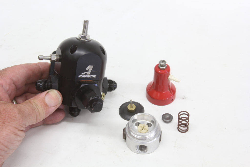
All of this magic is achieved by simply balancing pressures inside the regulator.
Underneath the dome of a typical fuel pressure regulator is a spring that sits on top of a rubber or Viton diaphragm. If we apply boost pressure to the top of the diaphragm, this increases fuel pressure. If we apply vacuum to the top of the diaphragm, it reduces fuel pressure. All this balances out the pressure experienced by the injectors.
Once again, we’ve taken a relatively simple question and applied a somewhat longer answer but hopefully this explains why the regulator is connected differently for different applications.
can i put a blower on my blue print balanced and blueprinted 383 c i stocker motor it has 10 : 1 compression i just want it for looks not to race and where do i find it thank you Gerald Hendon
My ls swap has a Corvette filter regulator at 58 psi,
I want to run a carburetor so I need to reduce psi down to 6- 7 psi so what regulator should I use ?
I have a 1995 Chevrolet 1500 I pulled the 4.3 engine out and put a 400 small block in,my question is how much horsepower do I have now it’s bored 40 over has 11:1 kieth black piston closed chamber heads with 202 valves and a LUNATI bare bone cam