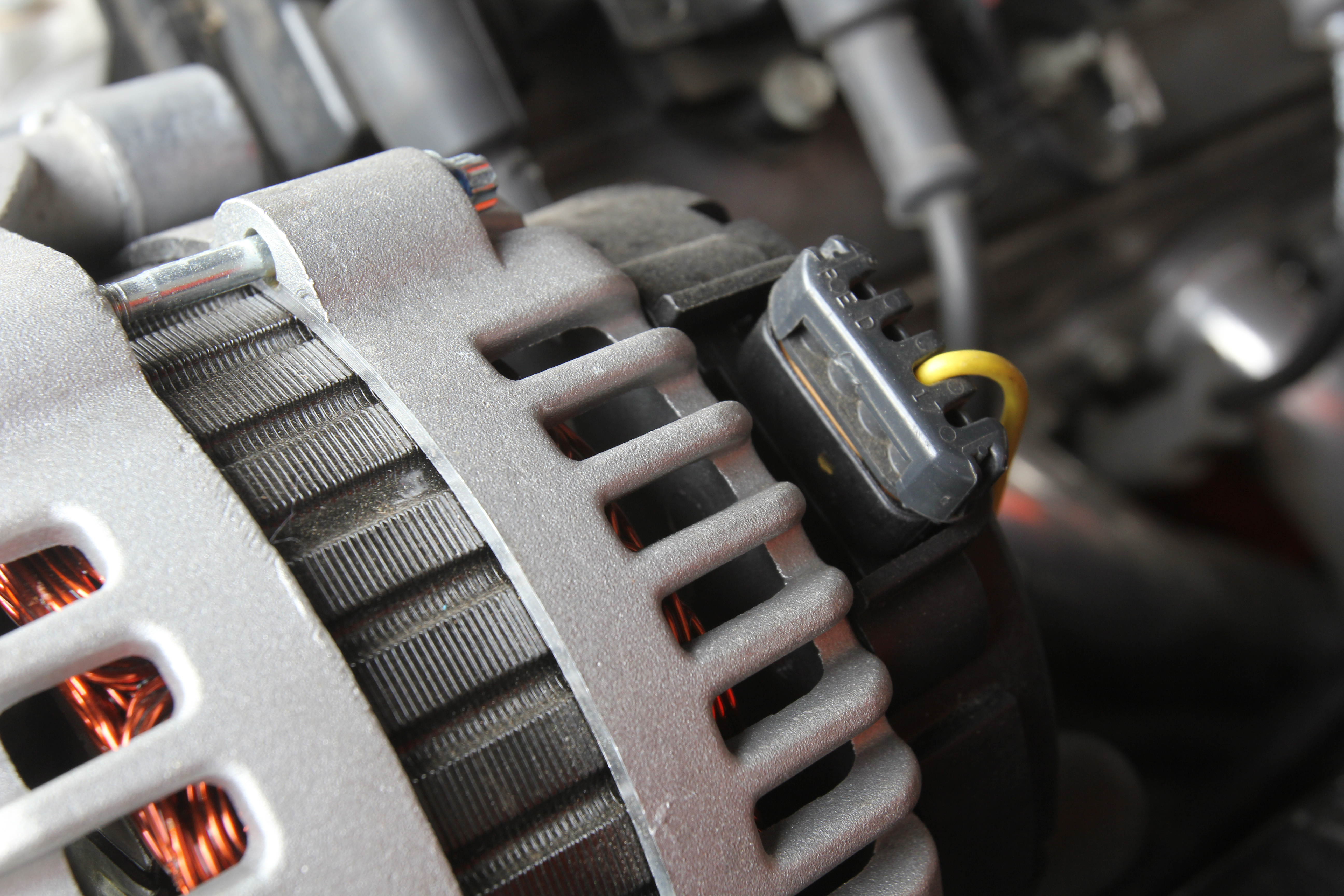
This is the plug-in wire lead to a late model LS truck alternator. The only wire that needs to be connected is the “L” wire, but it requires either a warning light bulb in the circuit or a resistor. Otherwise, damage will result to the alternator. (Image/Jeff Smith)
I did a LS2 swap in my ‘54 Belair. The engine came from an ‘05 GTO. It has a modest stereo system operating on a 10-amp fuse. It has a 16-inch cooling fan that operates on a 30-amp fuse and it will blow a 20-amp fuse if I try one. It also has Vintage Air A/C and all the normal stuff including power door locks and cruise control. The alternator that came with the engine died soon after I got if running. It keeps blowing the diodes in the rectifier. I went through three of the alternators that were supposed to be for the GTO. I then switched to a one-wire 120-amp alternator. It worked fine for about 6 months but now it seems to have killed the diodes in it too, or at least it has the same symptoms. The voltage drops as additional load is added until it decreases to 12 volts or down to 10.5 volts at idle with all accessories operating.
Do I need to go with a 180-amp alternator? Thanks, D.H.
…
This question originated from an earlier question posted here.
My first thought after I read your question is that it’s possible you need to add a resistor into the “L” or light circuit connector on the CS130D alternator. In the case of the GTO, this appears to be a different version alternator, perhaps a GM AD style.
On most late model alternators, if the warning light circuit is not employed, running without that resistance in the circuit will cause the alternator to fail. On the plug-in connector, there are four connections labeled P-L-I/F-S. The connector labeled “L” is the only terminal (of these four) you will need to connect to the vehicle.
If you choose to not connect a warning light in line (in series) with the wire terminated at switched (12v) power, then you must include a resistor. Our friends at Powermaster recommend an 82 ohm, 5-watt resistor. You can find these at an electronics store or online through a company called Mouser Electronics for less than $1.
Of course, the simpler route is just to hook it up to a warning light that’s already in your dash. Just make sure that power for the light is connected to switched power and you’re all set.
From your description, it appears the alternators have not really failed. They likely appear bad because the indicated voltage at idle is very low at 10.5 volts.
The issue is probably that the alternator is functioning but it doesn’t have the output capacity needed. In other words, the amperage demand at idle is higher than its capacity to generate. When this happens, the voltage begins to drop. We created this chart to list what you’ve described as already running on your car. These current draws are estimates.
| Component | Estimated Amp Draw |
|---|---|
| Fuel Pump | 12 |
| Radiator Cooling Fan | 25 |
| Stereo | 8 |
| A/C with Fan On High | 20 |
| Headlights | 10 |
| Taillights | 4 |
| Total | 79 Amps (Continuous) |
All alternators are rated at their maximum amperage.
This occurs at somewhere around 1,500 to 2,000 engine rpm. Assuming a 120-amp alternator, it is probably capable of closer to 100 amps at idle. This is also the cold rating—in other words rated at its highest efficiency at idle with the alternator at ambient temperature.
Once the alternator heats up under load, efficiency drops by 15 to 25 percent. So now your alternator is barely putting out 80 amps at operating temperature at idle. This brings the output at idle down to almost exactly what we have listed as your amp draw. This would create the situation where with the engine at idle, the voltage drops well below 12 volts. This is because the alternator cannot keep up with demand, not because the alternator failed.
But before we deep-six your current alternator, let’s see if we can help it run more efficiently.
The first thing test is to run the engine at idle and engage all of the high amperage draw components to put a load on the alternator. Now place the positive lead from your voltmeter on the power output terminal of the alternator and ground the other lead to the alternator case.
Let’s assume the voltage is around 11.5 volts. Now connect the voltmeter to the battery. Let’s say that it reads 10.5 volts. This means that the charging wire between the alternator and the battery has lost a full volt (1.0 volt) to resistance. An acceptable number is closer to 0.4 to 0.5 volts. A 1-volt drop indicates the need for a larger main charge wire.
You might need something as hefty as an 8 or even a 6-gauge wire.
Powermaster recommends that if the charging wire is 4 feet in length or shorter for an alternator output between 105 and 125 amps should use a 6-gauge charging wire. If the battery is in the trunk and the charging wire is 20-feet long, this will necessitate a 2-gauge wire. That is almost the size of a small battery cable.
So we’d recommend making sure there is minimal resistance in the charging wire circuit to the battery. Then re-check the charging system voltage at idle. If the system voltage at idle is still too low, then it’s likely you will need a higher output alternator to feed the electrical demand at idle.
Jeff – I just read another article about pulley ratios. Keeping in mind this guy has done an engine swap,run multiple alternators etc, is it possible that his pulley ratios are wrong causing the alternator to spin too low at idle meaning output at idle is too low?
Excellent read; Thanks!
I would recommend performing a voltage drop on the alternator ground side as well.