I have a ’66 Chevelle with a small-block and a TKO five-speed that’s been recently upgraded with better synchros. With the trans back in the car, I’ve noticed a bad vibration in the driveline at speeds above 60 mph. What’s weird is that when I have someone else in the car, the vibration is reduced. This tells me that the driveshaft probably isn’t out of balance but that it’s something else. Do you have any suggestions?
BI
Jeff Smith: If you’ve been reading this column for any length of time, then you probably already know that there is a short answer that most tech writers will offer and then there’s my much longer answer that attempts (sometimes successfully) to explain why this occurs.
My belief is that if we offer up the basics surrounding the question, you will be in a better place to understand what’s happening and figure out the solution to the next question on your own.
It’s a little like the ancient parable. The one about giving a man a fish will feed him for one day, but teaching him how to catch his own fish offers him a way to feed himself and his family for a lifetime.
So here goes.
The short answer is: It appears you need to change the existing pinion angle.
The best way to do that is probably with a set of adjustable upper control arms. This will allow you to change the pinion angle which should reduce or eliminate the existing vibration. In your case, it appears that the pinion is operating at an intersecting angle to the driveshaft. This will cause a vibration at speed. The reason adding weight with a passenger affects the vibration is that the intersecting angle has improved, but not eliminated, the problem.
I had a similar problem with my Chevelle many years ago on the Hot Rod Power Tour. With my Chevelle loaded with gear in the trunk, the car experienced a bad vibration on deceleration. The weird aspect was that it only occurred on Power Tour. That was the only time we put a lot of weight in the trunk. That weight changed the pinion angle and created a vibration. Our quick fix on the road (because we couldn’t change the pinion angle) was to raise the trans level by ¾-inch. Eventually, we determined the real problem stemmed from a sagging crossmember, causing the engine/transmission angle to achieve a 5 degree tail-down attitude.
But why did the vibration occur in the first place?
Imagine that you are Superman with X-ray vision, and by looking at the driver side of the car, you can see the engine and transmission, rear axle assembly and all of the suspension components.
The Chevelle’s rear suspension is what’s called a non-parallel four-link. This is also nearly the exact same rear suspension used in Fox-body Mustangs.
The lower control arms are essentially parallel with the frame and ground, but the upper arms are not only shorter, but also splayed out to form a rough triangle. This upper triangulation positions the rear axle assembly in the car so that it doesn’t need a separate link to position the rear laterally.
Also, the upper control arms are significantly shorter than the lower arms.
Now, imagine changing the ride height and moving the rear suspension through its travel.
You’ll notice that the pinion flange on the rear axle travels in an arc. At stock ride height, the suspension is designed so that the rear axle is at the furthest distance transcribed by that arc. For this example, let’s call this parallel to the ground, or 0 degrees.
As the ride height is lowered (suspension is compressed, or in bump, as shock tuners call it), the pinion angle will change. This occurs because the upper arms are shorter. So when the suspension is compressed, the shorter upper arms will tend to pull the top of the rear axle forward because they’re travelling in a shorter arc than the lower arms. This tends to push the pinion angle down (when looking at it from the driver side of the car).
In your description of the car, you didn’t mention whether the ride height has been changed.
But since we’re car guys, lowering or raising the rear ride height is possible. Let’s say that the car has been lowered one inch. We can also assume that the factory designed the upper control arms to position the pinion angle at its proper angle at the original ride height.
So when the ride height is changed, this will automatically pull the pinion angle into an increased downward angle. Now that we’ve established that the pinion angle changes with suspension movement, we can look at what effect this has on the entire driveline angle.
To further this discussion, we must look at the driveshaft operating angles.
In almost all production car cases, the engine and transmission are installed with the back of the transmission slightly lower than the front of the engine, giving this package a slight tail-down attitude. Now, let’s slip the driveshaft in place and bolt it to the pinion with the car at ride height.
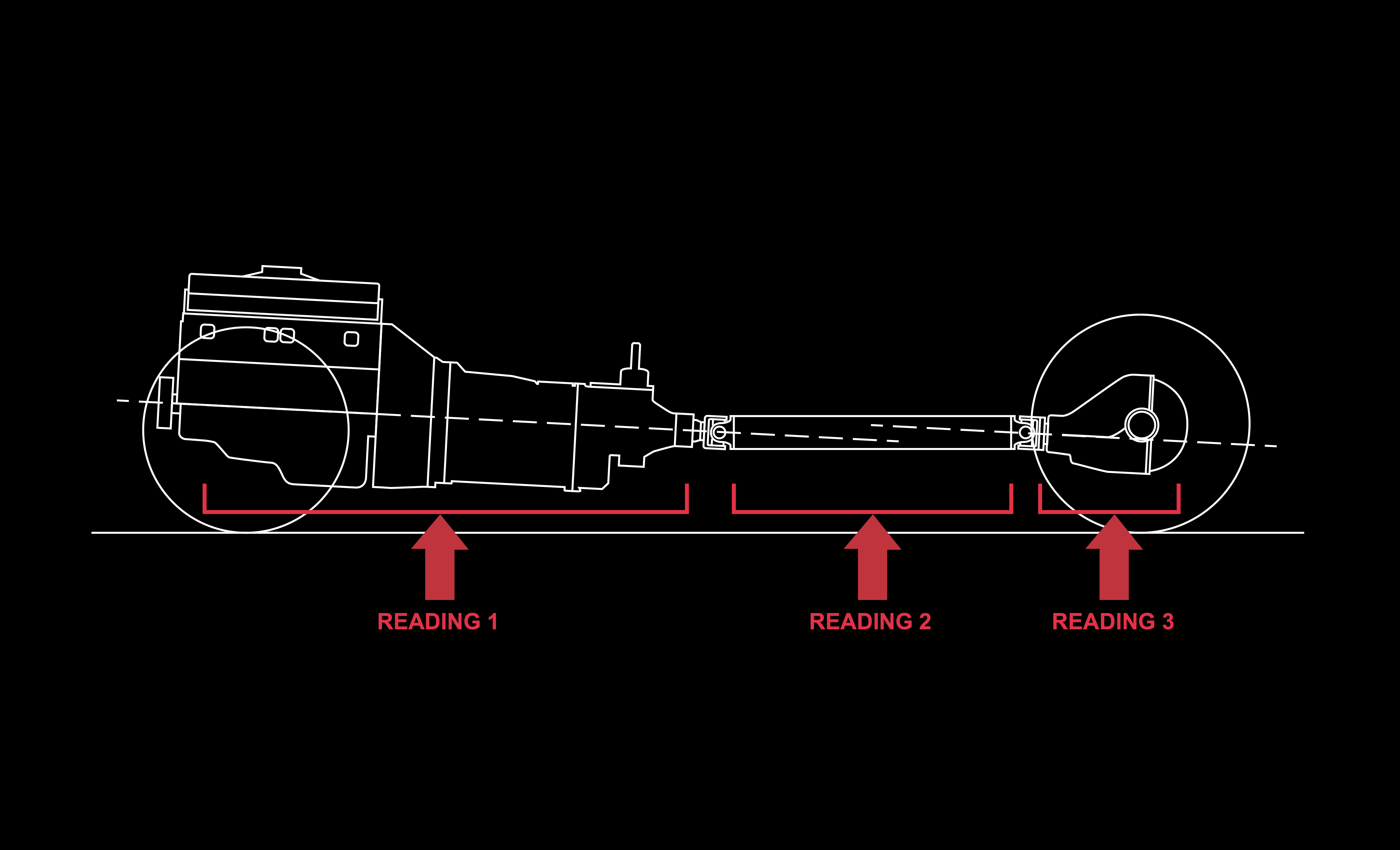
This creates three distinct operating angles.
The first is the front U-joint operating angle which is the angle created between the transmission output shaft and the front U-joint on the driveshaft. The second angle is between the rear U-joint and the pinion flange. The third angle is the combination of the first and second operating angles.
For a driveshaft to operate properly, it needs to spin within a given set of angles that allow both of the U-joints to spin, creating perfect circles. If the U-joints are not at the proper angles, they will make oblong or oval operating circles while spinning.
There’s a cool video created by Spicer Drivetrain Products that illustrates this idea perfectly:
When the driveshaft operates at intersecting angles, the U-joints spin in oval circles, and that creates vibration because the driveshaft isn’t operating at a constant speed. You eliminate the problematic intersecting angle by creating the proper driveshaft operating angle.
Now let’s go back to our Superman X-ray vision.
If the engine/trans angle is tail-down, then the pinion angle needs to be parallel, or close to parallel, with the engine/trans angle.
We’ll use specific numbers to illustrate this.
Let’s say the engine/trans is angled downward at three degrees and the pinion is angled upward two degrees. If we were to extend the operating angles of the engine/trans and the pinion, you can see that these lines will be within one degree of parallel. This arrangement is very close to an ideal overall driveline operating angle because the two angles are within one degree of parallel.
Now, let’s change the pinion so that its operating angle is two degrees downward. The extended line from the pinion angle will now intersect the engine/trans angle, creating an intersecting overall operating angle that generates the vibration you’re experiencing.
So the solution is to change the overall operating angle.
There are two ways to do this: One is simple. The other is far more difficult.
The difficult way: If we decide to leave the pinion operating angle at two degrees nose-down, the engine/trans angle would need to be raised to a minimum of a one-degree tail-up attitude. And this will probably be difficult since that TKO trans is already somewhat tight to the floor pan. We’ll assume you currently have the typical tail-down angle. Placing a ½- or ¾-inch shim between the trans mount and the crossmember will help, but probably not enough. In our experience, it may take 1½ to two inches of spacers to move the trans angle more than a degree.
The simple way: The second option is to change the pinion angle. Frankly, this is far easier.
With adjustable upper control arms, this gives you the ability to lengthen the upper arm which will raise the pinion angle from a nose-down to a more appropriate nose-up angle. Again using our original three-degree engine/trans tail-down angle, adjusting the pinion to a two-degree nose-up angle will put the overall driveshaft operating angle within one degree of being parallel.
(To address a question you might have: A nose-up pinion angle between two and four degrees would also be acceptable since it would still be within a degree of the engine/trans angle of three degrees.)
The adjustable upper control arms for your Chevelle will cost you about $230. Pay attention to whether the arms allow for adjustment after installation. Not all adjustable arms do. Some can only be adjusted by removing one end of the arm from the car. Other arms employ left- and right-hand threads that allow for in-car adjustment.
I have personal experience with the control arms from Global West Suspension which feature a spherical bearing in the front and offer left- and right-hand adjusting, but these are also a little more expensive than other adjustable control arm options.
Also make sure that each arm is adjusted to the same length as its partner. If not, the suspension will bind.
I recommend placing a long bolt through both holes of a stock upper arm and setting the adjustable arms at this length, and then lengthening them by one turn. This is usually a good starting point.
Ideally, you want to check the pinion angle of your existing driveline before making the change to ensure that your combination is as we’ve described. To do this, the angles must be checked at ride height. This is accomplished easily on a drive-on hoist. If you’re using a lift that contacts the frame, this will take some extra effort.
First, measure the rear ride height.
I do this by measuring the distance from the fender lip to the centerline of the rear wheel/axle.
Then raise the car, remove the rear springs, and use a trans jack to push the rear axle up until the rear wheels are positioned at ride height. For here, measure the engine/trans angle and the pinion angle.
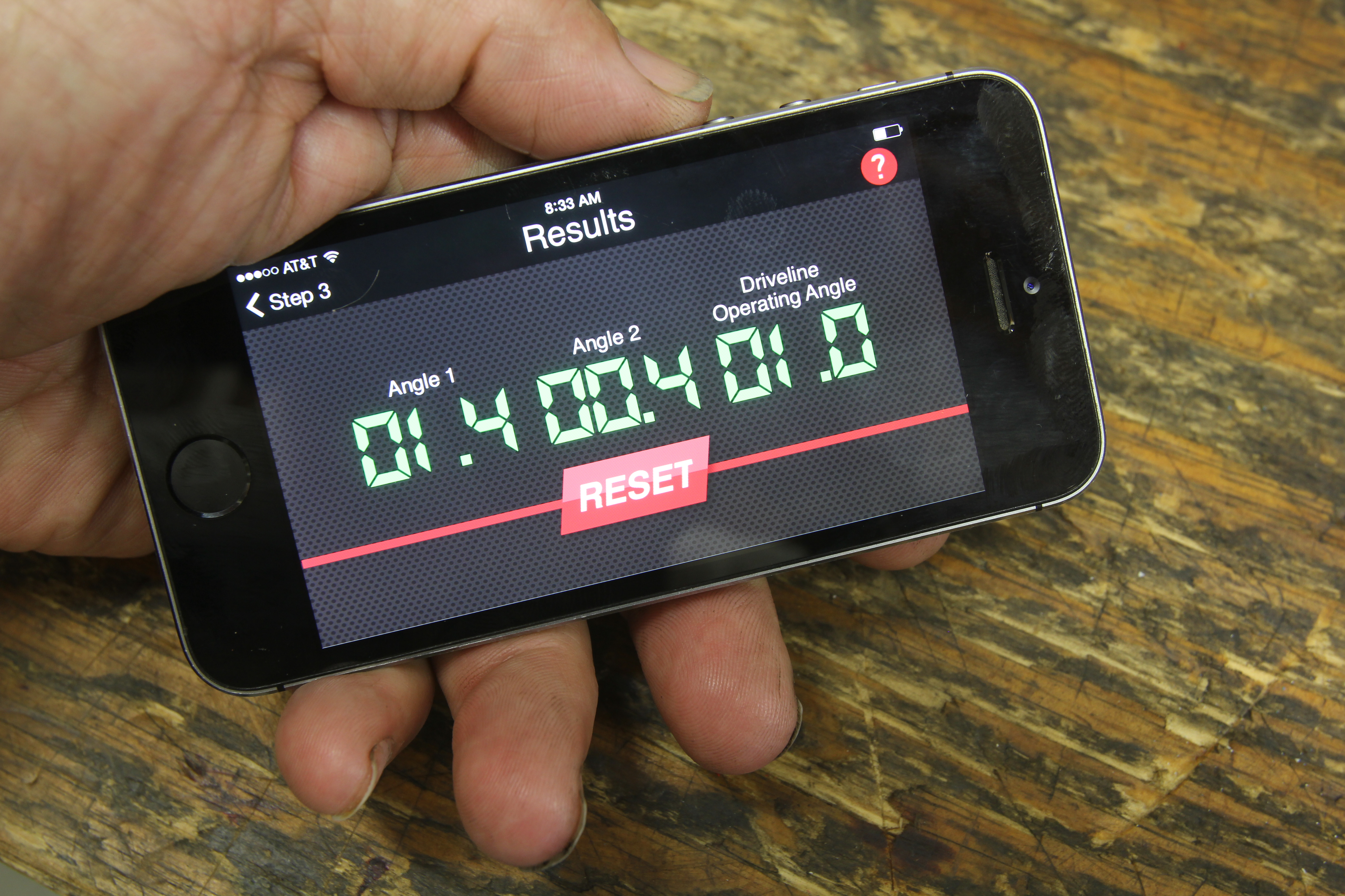
This is what the Tremec app final calculation screen looks like. If your operating angles are good, they will all display green. If not, they will display red. The app is free to download on your mobile device.
If you have a smartphone, you can download a free app from Tremec that uses the angle-finder in your phone to measure the engine/trans, driveshaft, and pinion angles. The app calculates the overall operating angle and gives you the results. It works well, but it’s critical that you measure the angles accurately. Don’t use the engine or trans oil pan as they’re notoriously inaccurate. Better to use the trans pan rail, if possible. You can find instructions for using Tremec’s angle finder app here.
I think a CV joint would cure the problem.
[…] Also: Ask Away! with Jeff Smith: How to Fix Driveline Vibrations by Adjusting Pinion Angle Monday Mailbag: Solving Recurring Driveline […]
Excellent article! Always knew the cause/effect, but had never seen it explained so well. the video from Spicer is a real eye-opener in this case. I use a magnetic pinion angle gauge along with some modified yokes that allow me to get front and rear readings then just “do the math”. One tip… always use the exact same pinion angle gauge at both ends. I’ve seen gauges by different manufacturers be off from each other by as much as a whole degree.
Definitely the best explanation of the physics and mechanical advantages and disadvantage that I have ever had explained to me. Thanks so much for your help and I so grateful because I am out of money on my 1996 grand Cherokee Laredo it is lifted .if it wasn’t for you I would be parking for a while.
Seem’s to me that if you increase length of upper arm the pinion will go down. What am I missing?
If you look at the rear axle assembly from the side – let’s choose the passenger side – we have a lower link and an upper link. Our pivot point will be the rear connection of the lower arm. If we lengthen the upper arm, that forces the pinion to go up because it is pivoting off the lower rear. If we shorten the upper arm, this will force the pinion angle to move downward. All of this is predicated on ride height. The moment we change the ride height in the rear, this alters the relationship of the upper and lower control arms. It is interesting that companies that make air bags don’t discuss how much a simple change in ride height affects not only front end alignment but also rear pinion angle. Hope this helps you understand this better. Another way to visualize this is to place two pencils – one short and one longer on a piece of paper. Place a dot for the two rear pivot points and then move the sharp end of the pencils same distance up and down and watch what happens to the angles. The shorter pencil transcribes a tighter arc which affects the pinion angle. It’s interesting how all this works. Hope this helps!
[…] Ask Away! with Jeff Smith: How to Fix Driveline Vibrations by Adjusting Pinion Angle […]
I have a 1969 chevelle 396 4 speed 355 ratio rear F 41 chevy suspension on air shocks. When i do a burn out i have bad wheel hop. I tried letting the air out of the shocks, it still hops. I changed all the bushings upper and lower to poly bushings, still have wheel hop. Will it stop if i put the QA-1 traction bars on it? Im trying to keep it original looking as possible and also not throw away alot of money either. Everybodys saying there product will stop wheel hop but nothing so far.
Replace rear wheel bearings and gears and now it only want to turn one way
I have a 67 firebird that I replaced the leafs on. The new leafs had around 1.5 inches more arc. Since then I get a cyclical vibration over 65 mph and a clunking upon deceleration under 30 mph. The clunking only happens for a very short time after a long trip, 45 miles or so. Since I had just purchased the car I assumed the clunking was u-joints but after replacing them the problem has persisted. Could the new leafs have changed pinion angle enough to cause this?
Hi Jeff. Checked my driveline trans is 4 drug low pinion 0 deg. Can you recommend a good set of adjustable upper control arms without breaking the bank. Thanks Tom
Hello Jeff, I have a 2016 Mustang automatic V-6 that has a drive line vibration. Driveshaft has been replaced 4 times and the Dff once. Vibration decreases for about 1500-2000 miles then returns at 50 mph and higher. Do you have any insight as to what the problem is with these models. Thank for your response.
Hey Jeff. I hope youre still answering questions about this driveline angle blog. I have a ’65 Chevelle. I just installed a new Currie 9″ rear end with Wilwood brakes, new contol adjustable lower and upper control arms and new 3.5″ balanced driveshaft. The engine was sloping 5* down, which I thought was excessive, so I shimmed the transmission and now the slope is 3.7* down. The driveshaft is at 1.6* down, and the pinion is parallel to the trans yoke at 3.7* down. I have tried several different pinion angles all the way down to 1.2* down, but cannot get rid of my low speed fairly severe vibration. The axle is centered and the bearings are good. Do you have any suggestions for me to check out?
I know it’s been a couple years, but I do. Take your driveshaft to a shop that can balance them on a machine that INCLUDES the yokes. In my case, I had a severe vibration that turned out not to be due to a balance issue. The D/S was perfectly balanced, but the runout measured by a dial caliper indicated that the D/S was not true (not perfectly straight). So, it was actually moving the yokes on both ends as it rotated. I suspect your issue is somewhere in this neighborhood, but before I paid the shop to look at mine, I:
– Balanced my wheels/tires & set my alignment
– Checked my suspension bushings, transmission crossmember bushings, the trans mount, and engine mounts
– swapped u-joints
– set pinion angle in accordance with this article
– replaced axle bearings
– ensured my pinion flange nut wasn’t loose
I also am experiencing a driveline vibration in my 19 63 1/2 Ford galaxy. The starts about 65 mile an hour on up to higher speed. I am having a 3 inch driveshaft made for it as it is a long drive shaft and had to start someplace. Can you tell me what the pinion angle should be on the differential. Thank you for your time I appreciate it
I want to get on your mailing list
Hi jeff,
I own a 1980 chevy c10 stepside. I have added a 6 inch flip kit in the rear and lowered the front 4.5 inches with lowering springs and spindles. Around 40 mph I get the vibration in the driveshaft that’s very annoying. My stepfather had a driveshaft input yoke that was too long and cut it down some. What should I do to help stop this vibration? Get the driveshaft looked at for it being possible bent? Get a new input yoke? I have heard people lowering their trucks and never having a vibration problem.
I know this is an old thread but I have to try.
I have a 64 Nova, stock rear springs and CPP front clip.
LT1 350 5 speed standard.
Motor and transmission 3 degrees down drive shaft 3deg down, pinion angle 4° down. What would you recommend for a pinion angle adjustment, the car seems to get vibration at cruising speed 6570 but under load it doesn’t seem to be there.
Thank you in advance for your help Jeff Taylor
Should there be any in and out movement in the pinion? Example: grab the pinion flange and pull towards the front of the truck and push to the back and it moves in and out a bit
Alright, old thread but I’m hoping you’ll help a girl out anyway 😉 As much as I’d love to be building a hot rod, I’m broke and new to the car build game (be nice lol.) Learned AFTER lowering my 2008 Scion tC 4″ that it literally changes EVERYTHING in steering, handling and operation as a whole… Shit. So, here we are!! I’ve yet to find roll center adjusters, adjustable lower ball joints, lower control arms, performance cv axles, cv spacers or basically anything to help me correct the situation!! Engine/trans shims/risers sound great other than the thickness on them would probably have to be pretty intense, mount bolts aren’t long enough lol. I’m on coilovers (really don’t want to raise it if I don’t have to… dropped it that low because I want it that low…) Any suggestions?? 4 zipper-torn, brand new tires, vibration regardless of shifting gears, wheels feel like they’re gonna fall off!! Thank you in advance!!
Help me out here. The problem is, is that my driveline is at the same angle as the output shaft on the transmission and the pinion. I don’t have enough movement in the transmission or the pinion to make enough angle on the driveshaft to trans/rearend to keep from vibrating.
Awesome info and expertly described! You nailed my problem down for me. Stock length uppers and lowers with a lowering kit and with a change in the mounting point for the lowers that changes instant center. I finally got mine up on a rack today and measured out the angles. it’s about 3* down (front to back) for the engine and trans, 1.7-2* down for the D/S, and 1.3-1.6* up (front to back) for the rear flange, which is what you call ‘nose down’. This means your vibration scenario almost exactly matches my measurements, and I was guessing that adjustable uppers would be my solution. Now, thanks to you, I know it is! I need to extend them out and achieve a nose-up attitude of somewhere near parallel with the engine/trans angle. Thanks so much!
This turned out NOT to be my only issue, but I firmly believe that I improved my vibration problem by matching the pinion & trans angles. The other issue turned out to be that my D/S wasn’t true. The D/S shop that checked it for me informed me that it was about .030″ out. They used a heat and cooling technique to bring it closer to true and it drastically reduced the vibration, but ultimately, replacing the D/S was necessary to fix the vibration I was experiencing.
Hi all so I built a 1950 Chevy on s10 frame air rid have a vibration at 55 to 60 new driveshaft trans done new axle new pinon bearings new wheels trier it all I have build lots of equipment hot rods and so this is driving me crazy tried all trans is 4.5 down diff 4.5 up driveshaft is 0 to the frame change it Angeles up down string lined front to back dump air while driving razed it up driving razed trans up had driveshaft chq love some input
Who knows about 2-piece crankshaft like on my 1960 cadillac deVille ?
For a two-piece driveshaft you only need to be concerned with the andle of the rearmost portion of the driveshaft. The front portion – is essentially an extention of the engine and transmission.
I have a 1967 Chevelle 396 with a severe vibration upon taking off from a stop. My transmission angle is 5.6 degrees down (front to rear) my driveshaft angle is 1.5 degrees down (front to rear) and my pinion yoke is 2.7 degrees UP (front to rear). My transmission is up as much as possible and almost hitting the floor. I added UMI adjustable upper control arms. Am I correct in thinking that I should raise the pinion yoke UP approximately 5+degrees so it’s angle cancels the angle at the transmission?
Yes – raise the pinion angle to within one degree of the engine angle so they are roughly parallel and this should improve. The engine angle is pretty severe but raising the pinion will certain help.