In the United States, OEMs are turning to turbocharging as a method to downsize engine displacement and increase fuel economy. At the other end of the spectrum, those in charge of developing high performance and racing engines are targeting turbocharging for substantial power gains.
The OEM’s regard GDI (Gasoline Direct Injection) as a key enabler for utilizing turbochargers to downsize the engine displacement. With modern direct injection coupled to variable cam timing, added power output generated by turbo boost is now exploited more fully than before without risk of detonation, yet with significant benefits in fuel economy when running under light load.
As a result, OEM’s are shrinking the displacement of the engine, leading to weight and fuel economy savings. However, when power is required, the turbo kicks in to provide the boost, adopting the feel of a larger displacement engine. Turbos for OEM applications are sized to provide the best combination of low-end torque and peak power.
In the aftermarket, turbocharging is a relatively easy way to significantly increase the power density of an engine. In simplest terms, adding more air and more fuel to an engine will create more power. Of course one must take care to assure engine and vehicle systems are adequately prepared to handle this additional power. Most systems will add an intercooler to reduce intake manifold temperatures and aftermarket ECU to control fueling and ignition. Depending on boost level, consideration for upgrades include (but not limited to): head gasket, head bolts, clutch, pistons, connecting rods, crankshafts, transmissions and differentials. All components will be exposed to the rigors of additional power.
Compressor Stage
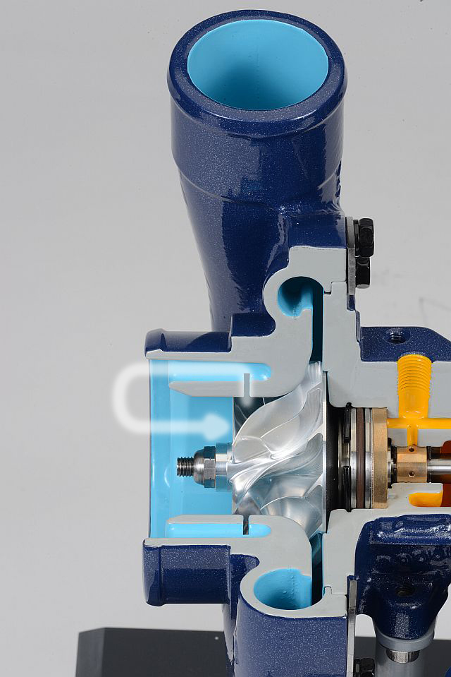
After determining realistic power level, selecting the proper compressor stage is the first step in turbocharging an engine. Turbocharger compressors are in simplest terms a centrifugal pump, which draws in ambient air though an air filter and compresses it prior to directing it to the intake.
The compressor housing is cast in aluminum and the compressor wheel itself is also made from aluminum, either cast or milled on a five-axis machining center. Some compressor wheels feature splitter blades which increase the flow capability of the wheel. If flow range is important for the application, the compressor can feature a re-circulation groove. This groove allows low-speed air to re-circulate back into the inlet and thereby extends the turbo’s operating range.
The re-circulating groove allows an excess of air accumulating between the compressor blades to escape, preventing the phenomenon known as surge. This measure doesn’t increase efficiency, but does improve the turbo’s map width.
Through the compression process, density and air temperature is increased. Feeding the engine with hot air that can reach temperatures of 300 degrees F can lead to detonation, and common practice is to run this hot charge of air through an intercooler prior to introducing it to the engine.
Turbine Stage
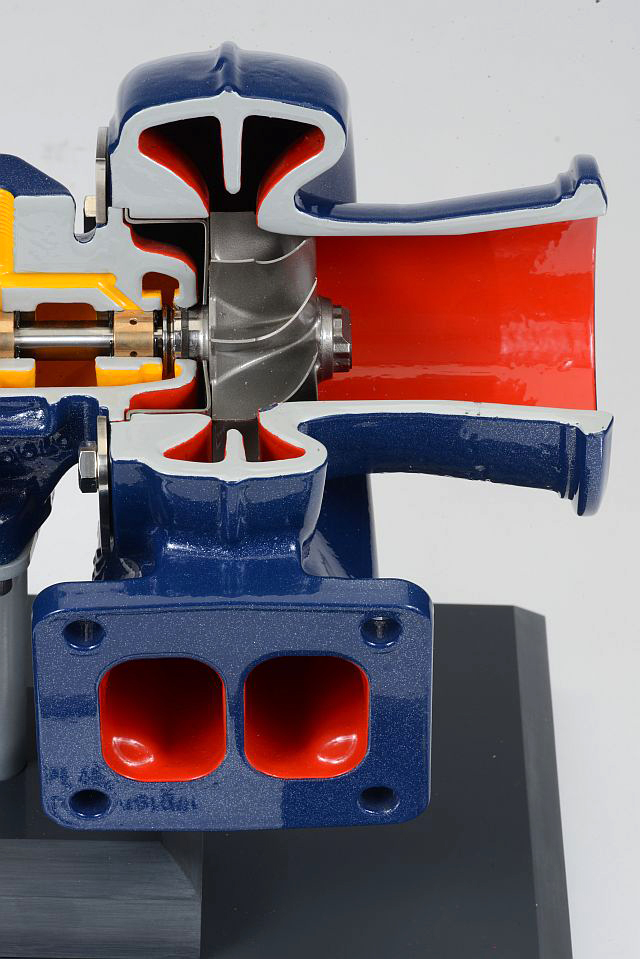
Turbocharging, by simplest definition, is a turbine-driven forced induction device that increases an internal combustion engine’s efficiency and power output by forcing extra air into the combustion chamber. This is achieved by utilization of exhaust energy to spin a turbine wheel, which is connected to the compressor wheel via a shaft. A naturally aspirated engine will allow exhaust energy to pass directly to the catalytic converter and muffler. However, inserting a turbocharger will harness this exhaust energy to produce the work required to spin the compressor to provide boost to the engine. Typical turbine wheels are formed from investment castings using high-nickel material called Inconel.
Rotating Assembly
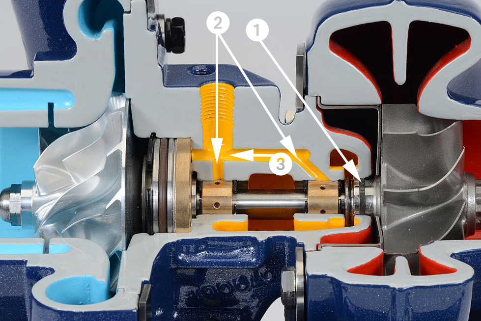
The compressor wheel and turbine wheel are connected via a steel shaft. In a traditional turbocharger, this shaft rides in a bearing system within a cast-iron housing. The bearing system consists of journal bearings to control radial movement and a thrust bearing to control axial movement. Radial clearances are specified in ten-thousandths of an inch.
Smaller turbochargers can easily exceed 200,000 rpm. Lubrication is critical and oil provides a thin boundary layer in which the bearings and shaft rotate. Oil also plays an important role in removing heat from the system. Piston rings are used on either end of the shaft to contain the oil and prevent exhaust/boost pressure from entering the center section. Due to the high exhaust temperatures in gasoline applications, water cooling is typically applied to reduce temperatures in the bearing housing and prevent oil coking during heat soak conditions.
Wastegate Assembly
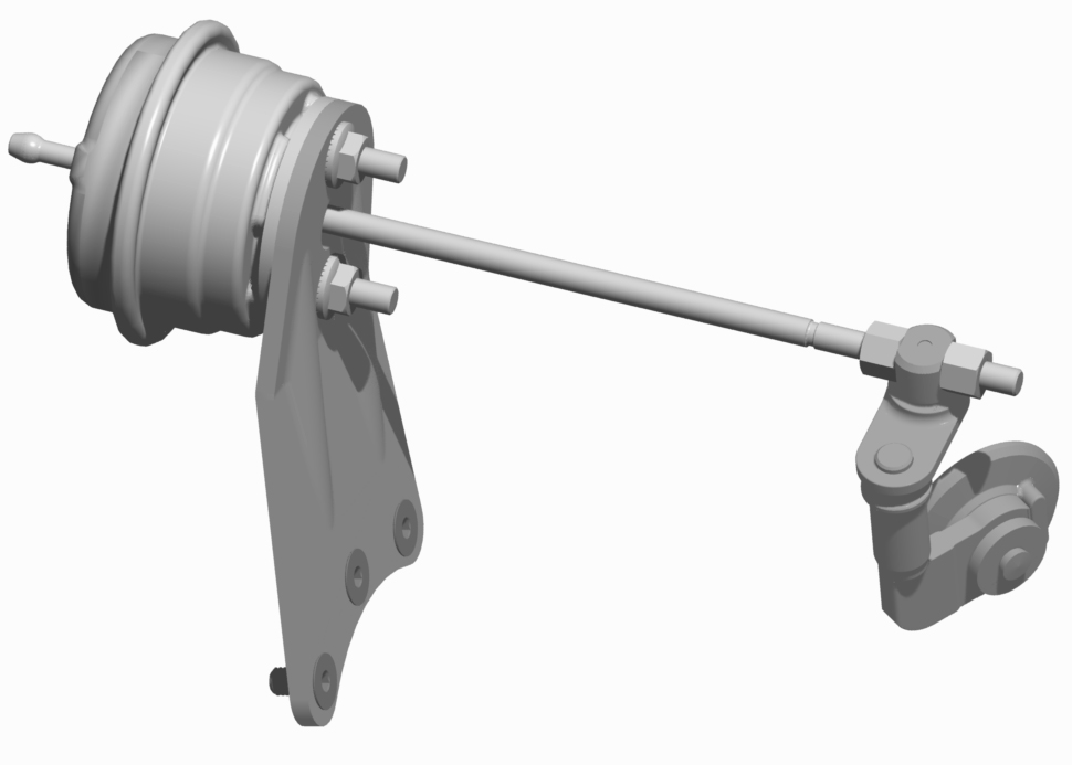
The wastegate is the control device for the turbocharger. A wastegate valve can either be internal (built into the turbocharger) or external (plumbed into the exhaust separate from the turbocharger). Internal wastegates typically comprise a flap-style valve while external wastegates used in the aftermarket are typically a poppet style. Either way, the principle function is the same in bypassing excess exhaust energy away from the turbine wheel and back into the exhaust stream after the turbocharger. This bypassing action limits the energy introduced to the turbine wheel and controls the overall speed and boost pressure of the turbo.
The wastegate valve is controlled by an actuator. Most turbochargers feature a pressure-controlled pneumatic actuator which will actuate based on the amount of boost pressure being produced.
Compressor Bypass (Blow-Off Valve)
Compressor Bypass Valves (CBV) or Blow-Off Valves (BOV) are devices incorporated into an engine system to prevent compressor surge and to keep the compressor wheel operating at high rotational speeds for transient operation. The CBV is part of the turbo and integrated into the compressor. The BOV is usually incorporated in the plumbing.
When the driver lifts his foot off the throttle pedal, the intake throttle plate on the engine closes. At this point the turbocharger is still spinning and creating boost. Since the throttle valve is closed, the boost has nowhere to escape except back into the compressor leading to a moment of instability known as surge.
Surge can be damaging to turbochargers as this rapid oscillation in pressure can quickly threaten bearing systems. To prevent this, a CBV or BOV is inserted into the system. When the user lifts his foot off the throttle pedal, the vacuum in the intake manifold actuates a valve which re-routes the post turbo compressor air back into the intake (as in a CBV system) or vents the pressurized air to atmosphere (as in a BOV system).
Due to lack of vacuum in a diesel system, CBV/BOV’s are not typically applied. However, there are now companies in the aftermarket offering electronic CBV/BOV which picks up a signal from the throttle-position sensor.
One missed factoid, Turbochargers are but one of many ways to SUPERCHARGE an OTTO Cycle engine. Supercharging being the practice of introducing air or air/fuel charge into an OTTO cycle engine at a pressure above atmospheric.
Thanks for the info on turbos I will be able to play with my 93 4.3 vortec in a couple of years I’m hoping for sooner than later so thanks for the info on turbos
Thanks for the 101, as I am entering the Turbo world with my 83, 944, NA. I am being coached by a trained Porsche Tech, but sometimes you need that A B C method.
At what milage is a engine to old to take a turbo ?
L Hamilton, You’ll need to consult or do plenty of research. Even a fresh naturally aspirated will only endure the high compression numbers a turbo produces after a rebuild with specific upgrades. There are kits for popular engines available to simplify resourcing. A shortlist would be low compression pistons, upgrade gaskets, preferably heavy duty head studs (ARP or APE, etc.), a turbocharger specifically flow-matched/sized to the engine, a purpose-built exhaust, high pressure fueling (fuel Injection is most tunable), intake boost feed piping, a surge chamber, a pressure relief or BOV (blow-off valve), a fuel pressure regulator, tunable computerized fuel management, an oxygen/fuel monitor with precise O2 sensor exhaust placement and operator-viewable gauge, a surge chamber, an intercooler (with custom plumbing), among other things. Then an aficionado will dynomometer tuning for correct fueling with maximize horsepower and torque. It may sound complex, but isn’t all that bad. The rewards can priceless, or result in catastrophic failure due to mistakes. Good luck!
[…] Again, this is a really, really simplified explanation. If you’re looking to get in the weeds here, we recommend this article written by automotive engineer and friend of OnAllCylinders, Doug Erber: Turbos 101: Examining the Fundamentals of Turbocharging […]