Most of you guys with manual transmissions probably know if you have a cable-operated or hydraulic clutch release bearing. But how many with a hydraulic setup know what type you have, and if it’s the right one?

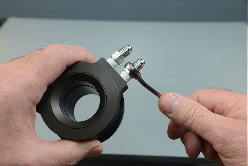
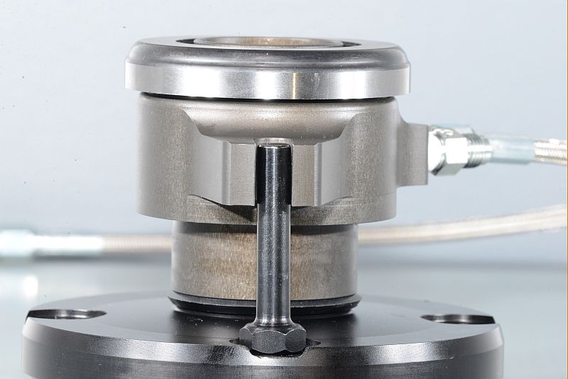
We spent a little time talking with Ram Clutches about hydraulic clutch release bearings. There are two basic styles: constant-contact (bearing always touching the clutch fingers) and intermittent (operates only when the clutch pedal is depressed) According to Ram, the intermittent style hydraulic bearing is better for high performance use. It has a greater adjustment range and is quieter than the constant-contact type.

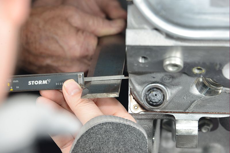
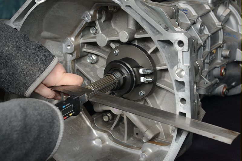
High performance, intermittent style release bearings need to be properly gapped at rest. Excessive gap between the contact face of the release bearing and the clutch fingers causes improper release. Too little gap can cause the bearing to over-travel and collide with the snap ring, or cause slippage as the clutch wears and the fingers move back, making contact with the bearing.

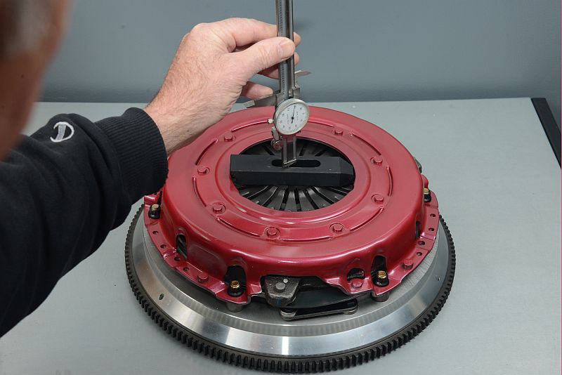
Ram recommends single disc clutches have a 0.150-inch gap between the bearing and clutch fingers, while dual-disc sets require a gap of around 0.200-inch. The extra 0.050-inch gap for the dual disc clutch prevents the clutch fingers from hitting the bearing as the clutch discs’ friction material wears.

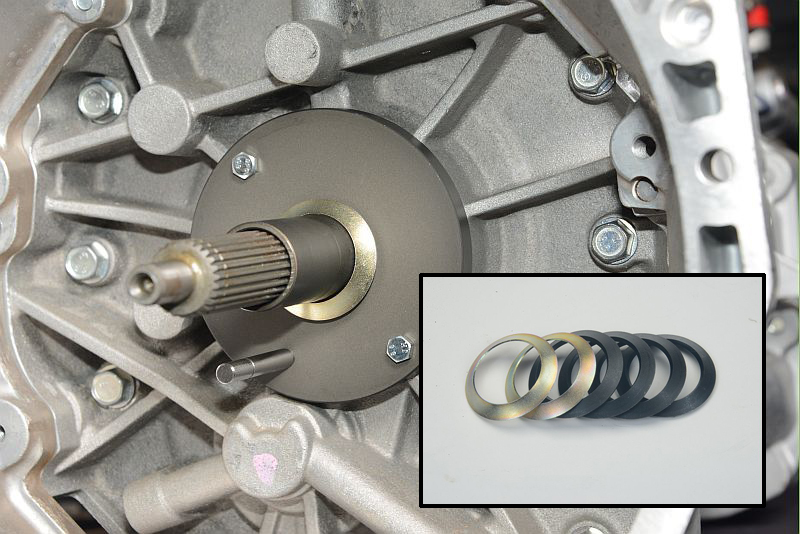
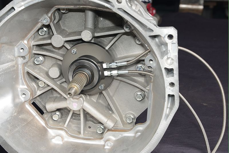
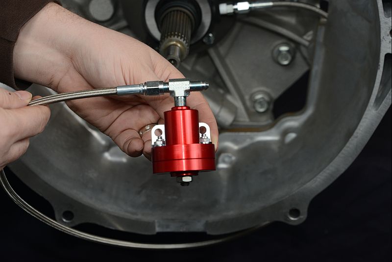
Follow along in the slideshow below to learn how to install and properly gap a Ram hydraulic release bearing on a single disc clutch.

installing fittings into a hydraulic throwout bearing
fitting a nipple onto a hydraulic fluid bleeder line
measuring for a transmission input shaft
checking clutch height with a dial caliper
installing a throwout bearing onto a transmission output shaft
spacers and a transmission output shaft
hydraulic throwout bearing fitted onto a transmission output shaft
hydraulic throwout bearing

The first task is to install the hydraulic fittings in the bearing housing. The best way to seal the fittings is by applying Teflon tape to the male threads. Do not use liquid sealants as the fittings will leak. Tighten the fittings with a

The bleeder line, which is the shorter of the two lines fitted to the bearing housing, goes in the upper port of the housing to ensure efficient bleeding. Use Teflon tape on the two-piece fitting.

Three measurements are required to establish the correct longitudinal position of the release bearing on the input shaft. Using a straight steel bar measure the distance between the crankshaft flange and the machined face of the engine block. Subtract the thickness of the straight bar from the measurement and record the resulting dimension in the ‘Dimension A’ box on the bearing instruction sheet’s diagram. In our case, the measurement is 0.300 inch.

Next, measure the height of the clutch. Bolt the clutch to the flywheel, lay a straight bar across the clutch fingers, and measure down through the fingers and center hub of the disc to the back flange of the flywheel. If the back flange of the flywheel is recessed, set it on a pedestal to obtain a true measurement. Deduct the thickness of the straight bar and record the dimension in the ‘Dimension C’ box on the setup diagram. Ours was 3.050 inches.

Install the stud on the bearing guide collar and secure the collar to the bellhousing. The stud prevents the bearing from rotating. Slide the bearing over the collar and measure from the face of the bearing to the bellhousing mounting flange. Remember to deduct the thickness of the straight bar and record the amount. Our measurement was 3.650 inches. To calculate the third measurement, add Dimensions A (0.300 inch) and C (3.050 inches), then subtract this sum from Dimension B (3.650 inches) The result is .0300 inch, which is the gap between the bearing and the clutch fingers when the bearing is fully retracted.

Ram aims for a 0.200 inch gap on dual-disc and 0.150 inch on single-disc clutches. To reduce the gap, remove the bearing and place the appropriate amount of cone-shape shims behind it. Some shims provided with the bearing measure approximately 0.100 inch, others measure 0.045 inch.

Place a straight bar across the bellhousing flange and recheck the gap. If the gap is acceptable install the hydraulic lines. The upper line is the bleeder, the lower line goes to the master cylinder.

Check the length of the drive stud with the bearing fully extended. The stud must not come in contact with the clutch cover. If the stud protrudes through the bearing housing and threatens contact with clutch cover, shorten the drive stud.

Hydraulic bearings often engage high on the travel stroke of the clutch pedal, which can be uncomfortable. Placing a Ram pedal adjuster in the hydraulic line just before the master cylinder lets you place the pedal at any clutch engagement position you prefer. The pedal adjuster mounts on the firewall or fenderwell.

Share this Article