I want to install an electric fan in my ‘67 Mustang and I’ve been told that I have to use a relay to wire it properly. I hate to admit this, but I really don’t understand how relays work and why I need one. I know that I can’t just hook the fans to a big mechanical switch because then I have to remember to watch the temperature gauge. Can you explain how these switches work in terms that anybody can understand? Thanks.
JR, Albany, NY
Relays are really pretty simple but can be somewhat intimidating until you understand how they work. Relays are basically like a heavy-duty electrical version of a large mechanical switch for components that demand high current loads. A large, clunky switch in your dash would also need a large, heavy wire running from the battery to the switch and then another from the switch to the electric fan. This is the 21st century and we can do better than that.
Let’s remove that big switch and replace it with a tiny little relay that does the same thing. The relay uses a tiny amount of current to trigger the larger switch in the relay, which is far more efficient and actually safer. Imagine running fat 8-gauge wires all the way from the battery to under your dash. Not only is this impractical, but with 30 to 40 amps of current running through the wires and the switch, this borders on hazardous. The beauty of the relay is that you can mount it in between the alternator and the electric fan in the engine compartment with a short, big lead running from the alternator to the relay and then from the relay to the fan. The longest lead is from the relay to your under-dash switch and it can be a tiny 18- to 20-gauge wire because the relay does not require high amperage to make it operate. In fact, all late model cars use relays controlled by the computer to trigger all sorts of high-load items like a fuel pump, electric fans, air pump for the suspension, and other similar components. Computers generally operate on 5-volt circuits and that’s all it takes to trigger the relay.
Another excellent reason for using a relay is voltage drop. Using our original mechanical switch idea, long wires create resistance. The longer the wires, the more voltage is lost to even a tiny amount of resistance. So by mounting the relay near the battery and the load (the fan), we reduce the length of the large diameter wires necessary to route the electrical power to the fan. By doing this, more voltage and current arrives at the fan and less is lost to resistance. This is important because electrical devices are intended to run at their designed voltage. When only 12 volts arrives at the fan instead of 14 volts, for example, the fan will not run as fast because its electrical power source has lost a bit of its power. By using a relay mounted close between the alternator and the fan, the charging system can deliver all the power. This makes the fan not only work more efficiently and last longer, too. Reduced voltage to the electric motor means it runs slower and hotter. This is like running a high performance engine with a dirty, clogged air cleaner—the engine runs but it’s not happy and far less efficient.
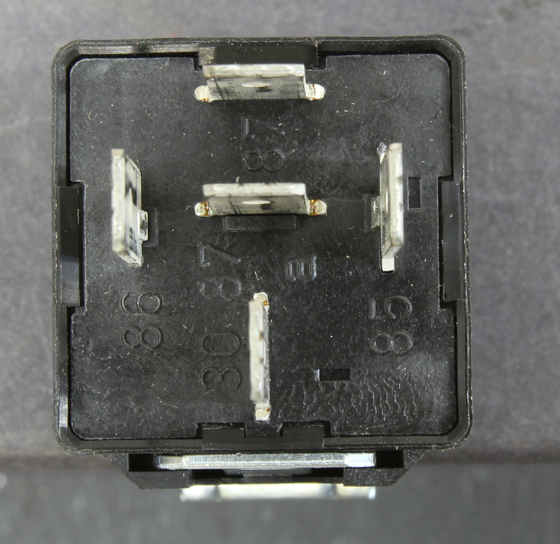 So now that we know why a relay is a good idea, let’s dive into how to wire one of these babies. The photo at right shows the bottom of a typical five-pin Bosch 30-amp relay. If you look closely, each pin is numbered. We’ll take each one separately. The bottom pin is marked “30”—this pin connects directly to a 12-volt positive (+) terminal that is live all the time. Opposite from the 30 pin is the 87 pin. Connect that one to the component you want to power—in your case the electric fan’s 12-bolt positive connection. This leaves two other connections—we will ignore the center pin (87a) for the sake of this discussion .
Next is the 86 pin (on the left). You might have guessed that we need a trigger, which is a switched 12-volt signal coming from the ignition switch. This leaves the far-right pin—number 85. The usual schematic will tell you that this is a ground, which is correct except that as soon as we ground this, the fan will run with the ignition switch in the on position. You probably don’t want that fan to run constantly. That’s why most electric fan companies supply a slick water temperature switch that is set up to complete to ground when the coolant temperature exceeds a given temperature like 195 degrees. For example, Summit Racing sells a complete electric fan relay kit that includes a relay, the harness, a circuit breaker to protect the system from accidental overload and a thermal switch. This switch is great because it triggers the fan at 185 degrees and then turns the fan off when the temperature drops below 170 degrees. Cheaper switches merely toggle around the trigger point, which means the fan is constantly turning on and off—very aggravating.
This kit also includes a circuit breaker. These are handy devices designed to disconnect the circuit should the current exceed its rating. Generally, the circuit breaker should be rated higher than the fan’s constant load.
 There are a couple of things you should know when installing this kit, especially the thermal switch. If we look at the diagram of the relay at left, it’s clear that the system can only be switched on when the ignition key is on and the 85 pin—the ground—completes the circuit. Most installers like to use PTFE tape when installing the trigger into the cylinder head. Can you see the problem? If the tape really does its job, it will insulate the ground circuit and even though the switch works just fine, it won’t find a ground because of the tape. The correct way is to use a small amount of pipe thread paste to seal but still allow a solid ground circuit. Often, the installer will blame the relay or the switch as bad when in fact everything works just fine if there’s a good-enough ground.
Another issue that often crops up is that end-users blame the temperature switch because it triggers at improper temperatures. Often, complaints are that the fan triggers “too soon” as viewed on their temperature gauge. This can happen because the temperature switch is located in the cylinder head near the exhaust ports where coolant temperature can be 10 to 15 degrees hotter than coolant located near the top of the engine at or near the thermostat where the cockpit temperature gauge is located. Plus, there is always the issue of how accurate your temperature gauge is relative to the coolant switch. All of these variables can add up to differences in when the fan switches on and off.
Finally, we mentioned earlier that electric motors tend to run more efficiently when supplied with sufficient voltage. One way to ensure that your electric fan delivers all the cooling power it is capable of producing is to check the power source. I would suggest locating the power source for the relay and fan at or near the battery. On many older muscle cars, you can use the horn relay buss bar as a convenient source for the power. You can also perform a quick check of how much power is present at this location by starting the car and use a multimeter to check voltage at the back of the alternator. Generally, this will be around 14.0 to 14.5 volts at idle. Now check the voltage at the buss bar or wherever you are sourcing the power for the fan relay. Let’s say our alternator checks at 14.5 volts. If the horn relay checks at only 13.5 volts, this is a voltage drop of one volt and there is excessive resistance in the wiring harness. Often, this is due to a corroded connection, undersized wiring, or both. The best thing to do is to upgrade the charging wire and/or connection to produce nearly the same voltage as found at the back of the alternator. This will produce maximum voltage to the fan, which will both allow it to work more efficiently and also last longer.
this is an excellently written article, very clear, understandable instructions.
Any one needing to install, or troubleshoot a relay or electrical accessory should
have no problem at all following these instructions.
Thank you for this wonderful article. Im a DIY kind of guy and always depend on experts like yourself. With out guys such as tourself would need to spend thousands at the shop.
Been a fan of Jeff’s work for decades. But this article is perhaps the most informative piece from him I’ve ever read. Thanks Jeff!!
Hi Professor Jeff,
I have an interesting problem that so far no one has been able to answer. I have almost completed a recumbent trike (3 wheeled bicycle, 2 in front, on wheel in back). I’ve got the motor and all the mechanical things done and now I’m trying to complete the thing that most eBike builders don’t so, and that’s wire in an kill/off on switch. Because of space considerations, wiring a large automobile or marine kill switch is next to impossible.
But, unplugging and plugging in a pack is both impractical and can be dangerous. and also since we are literally sitting on or in front of a huge energy pack of lithium Ion (LiPo) batteries, the idea of a cut off in case of a fire or run away is not just necessary but life saving essential.
My years of building and fixing cars gave me the idea of using a relay and putting a switch right in front of me in case of emergency, (I’m sitting 4″ above my 52v, 70ah battery, right uner my left thigh, and some anatomical parts I came into the world with, and like to keep for sentimental reasons). I have even put Nomex under my nylon mesh seat which, if it caught on fire would have be quite a problem.
So the idea of a relay to do the nasty work of managing the high voltage, high amp battery seemed a natural one. But there are some problems that don’t come in play when you’re talking using internal combustion engine on a boat, truck, car, snow mobile or anything that is self powered. Unlike these aforementioned items, the bike just “takes’ power and gives nothing back, so a relay would be draining the power needed to power the bike.
Which leads me to this question, and no one, and I mean I’ve looked everywhere and asked every place and even manufactures and vendors the same question. how much power does it take to operate a relay that would work to isolate the battery (turn off and on) with a switch or key? How many amps, how much drain per hour for instance? Are there any relays that would be able to switch a battery on and off (I think the batteries wire gauge is about 10 gauge) while being miserly in current draw to keep the relay circuit closed (on).
Anyone who could offer help in figuring this out, especially with specificity as far as what parts would be good to try. No one in the DIY ebike (and specifically the recumbent old timers like me) have an answer (and I’d like to be able to spread the word. I can’t stress how many lives and accidents this might prevent. One thing that happens sometimes with an energized bike is if someone who is not sitting on the bike accidently hits the throttle, they can have the bike run away and possibly hit a child or someone. So this would be such a great thing to solve.
Any renaissance men out there like me? I challenge the scientific minds of the world to come together in the idea of peace and solve this mystery (Ok, I stole that line from Ronald Reagan’s Star Wars speech, but heck it sounded good huh?)
Thanks very much.
Victor
Look at someone like “Curtis Albright” for what is called a “Line contactor”. It’s a large relay used to do exactly what you’re talking about in battery powered industrial equipment such as forklifts.
This is indeed a fantastic article. I remember how long it took me to use relays properly back at mechanics school haha. If I only had it explained this way… doh…
Thanks..
That’s an article helpfull. Realy hope more article in future !
[…] a coil) is used to pull a set of contacts, or pins, together. You can read our earlier post on How Relays Work for a more detail description of how relays […]
[…] remote-controlled switches, actuated by an electromagnet. You can learn how they work in this Jeff Smith Ask Away! article and read where to use them […]
Damn, I remember how long it took me to use relays properly back at mechanics school. If I only had it explained this way… lol
So you don’t have to tap into the battery post and from what I read I can tap into the alternator charging wire… this correct?