Working around automotive electronics tends to make a lot of gearheads really nervous. But the truth is, if you start with the basics, you will probably find that vehicle electrical systems are pretty straightforward—for the most part anyway.
To that end, we want to introduce you to the electrical multimeter.

Outside of maybe a simple electrical test light, a multimeter is the most essential automotive electric diagnostic tool you’ll ever use. But if this is your first foray into the electrical world, a multimeter can look quite intimidating. While model features may vary, it’s easy to be overwhelmed by all the numbers, symbols, and terminals on a typical multimeter.
But here’s the thing—for basic diagnostics on an ordinary car’s electrical system, you may only need to use a handful of a multimeter’s capabilities. That means, if you ignore some of those advanced features, a multimeter starts to get a lot more user-friendly.
In fact, we’ve whittled a multimeter down to three essential functions that’ll you’ll frequently use when working on a vehicle’s 12 volt electrical system. Get familiar with these three capabilites, and you’re well on your way to diagnosing and fixing your car, truck, or SUV’s electrical system.
In addition to a quality multimeter, a good set of electrical test leads comes in really handy for this sort of work, so we recommend grabbing a set of alligator “jumper” leads before you dive in here.
3 Essential Multimeter Functions Every Home Mechanic Should Know
***
1. Checking Electrical Continuity
The ability to check continuity on a multimeter is about as basic as it gets—yet it’s still an incredibly handy feature.
“Continuity” is fancy way of saying that there’s a solid electrical path through the electrical system. In other words, checking for continuity is checking for breaks in a wire, loose or missing electrical terminals, or damaged traces on a circuit board.
If you’ve ever used a test light probe, then you’ve been checking for continuity. Yet, a test light probe requires an external power source (your car’s battery) to work. A multimeter has its power source built into the unit itself, which means you don’t have to have power to the wire or circuit board you’re checking—which can eliminate a ton of hassles and headaches.
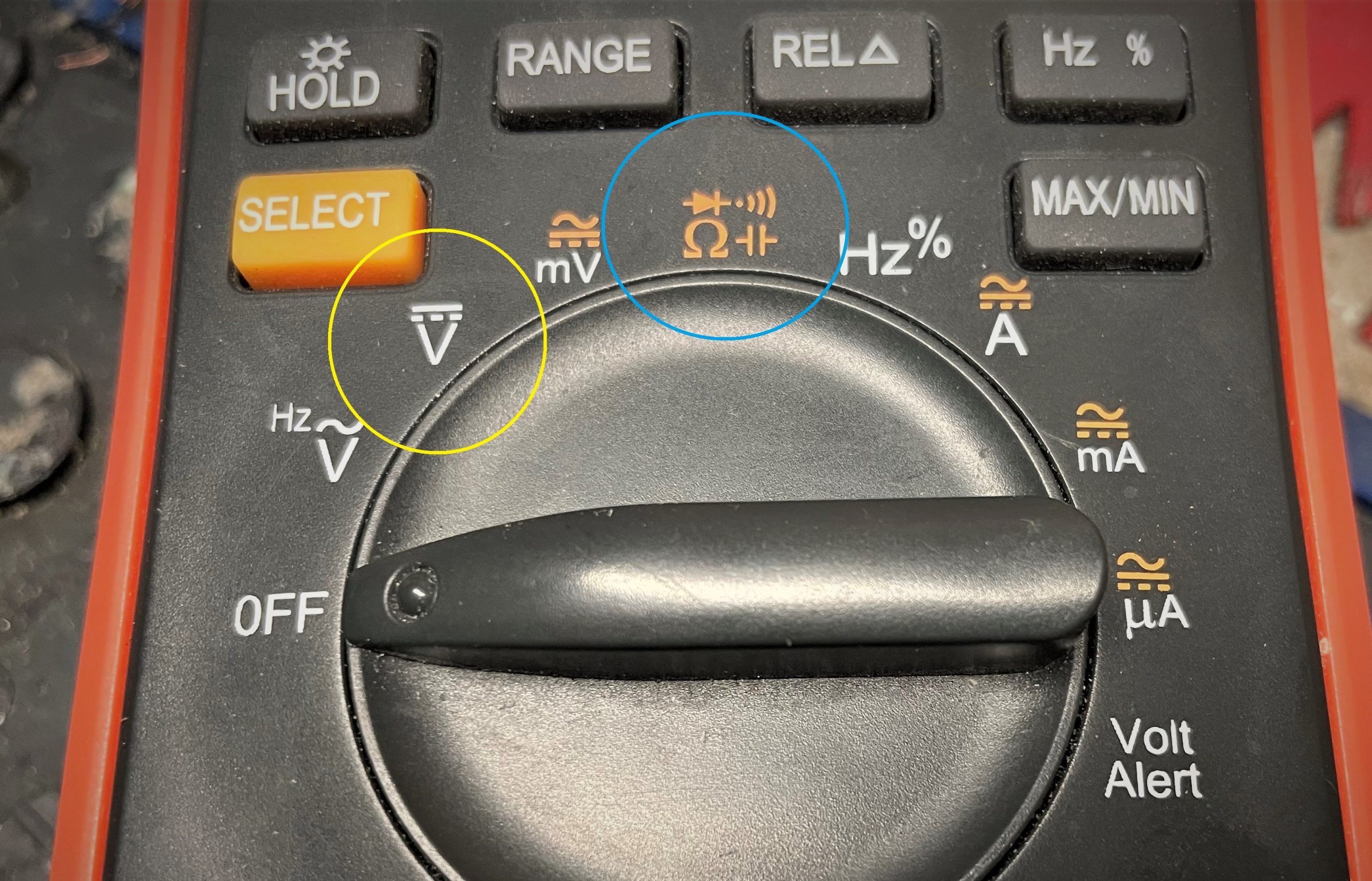
To check continuity, first move the multimeter’s big knob to the Ohms Omega (Ω) symbol—note that we said “Ohms Omega” and not “OLDS Omega” there.
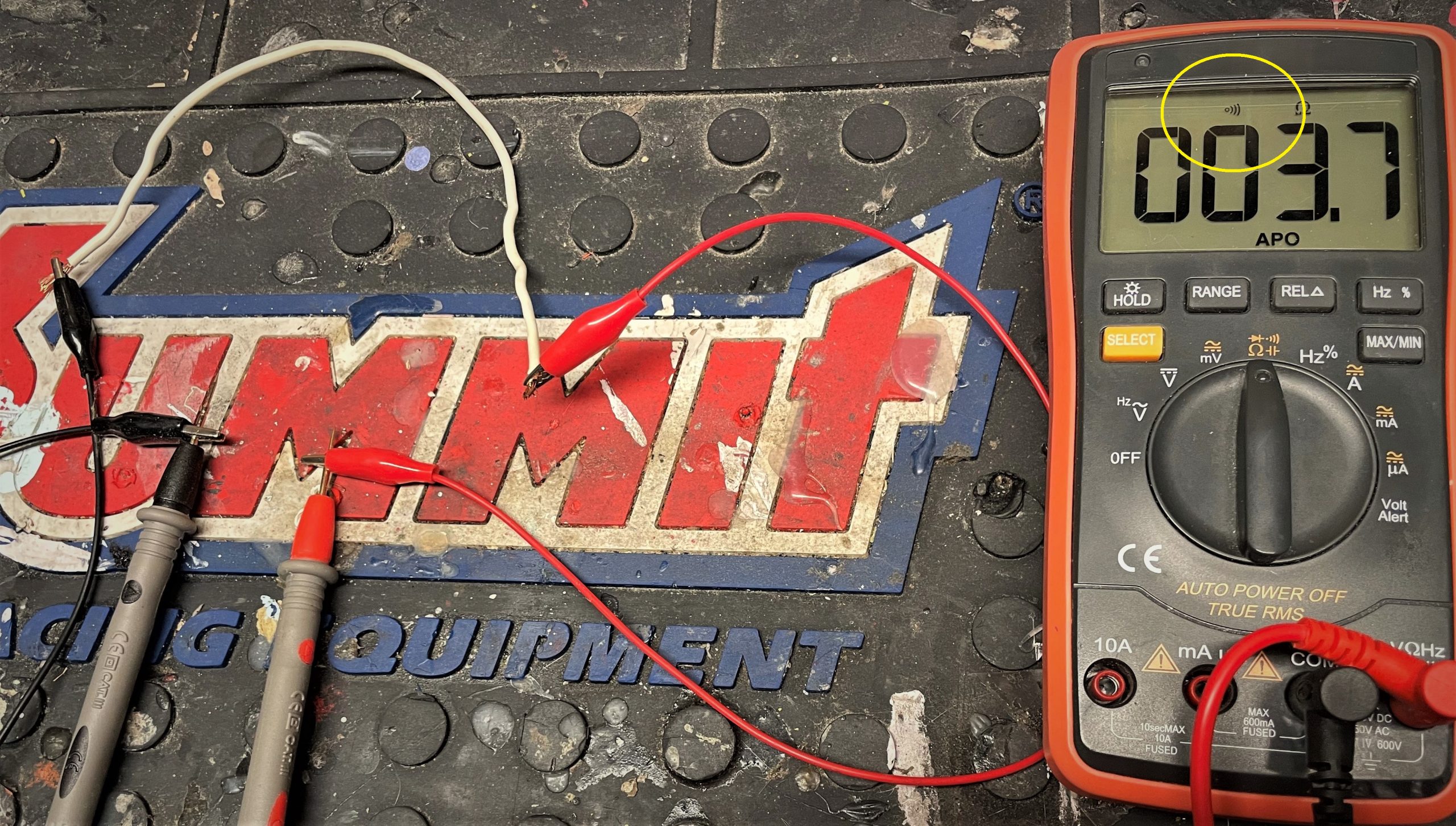
Now some (but not all) multimeters have a continuity setting that uses an audible beep tone to confirm that there’s continuity in your wire or circuit. Simply connect one probe clip to one end of the wire or terminal and then touch the probe to the other end. If you hear a beep, then that circuit is good and you have continuity. If you don’t, it’s time to examine the wire, circuit traces on a PCB, or the terminals and connectors along the way.
But! If your multimeter doesn’t have the audible continuity beep feature, no worries, because there’s still a way to check continuity using the multimeter’s resistance function. Read point three below and we’ll discuss that process in detail.
***
2. Checking & Measuring DC Voltage
This is the obvious one: You can use a multimeter to check DC voltage levels—it can tell you a lot about the health of your battery, charging system, and the overall condition of your wiring harness.
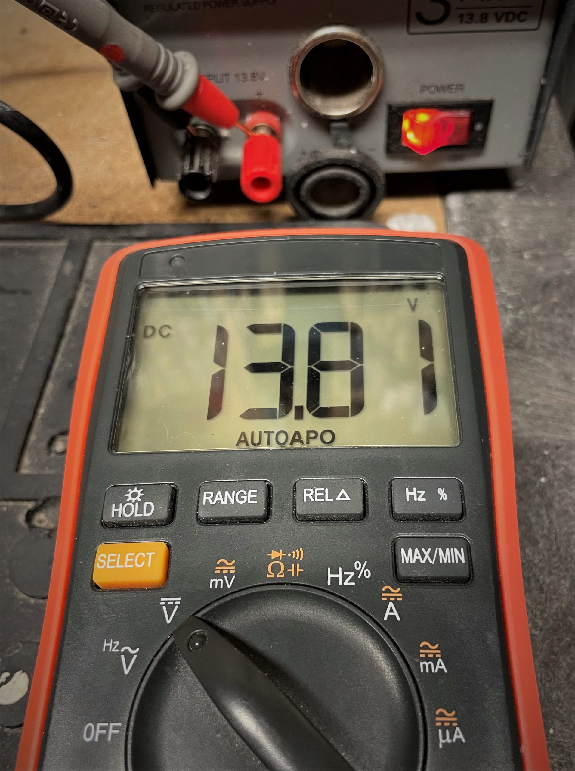
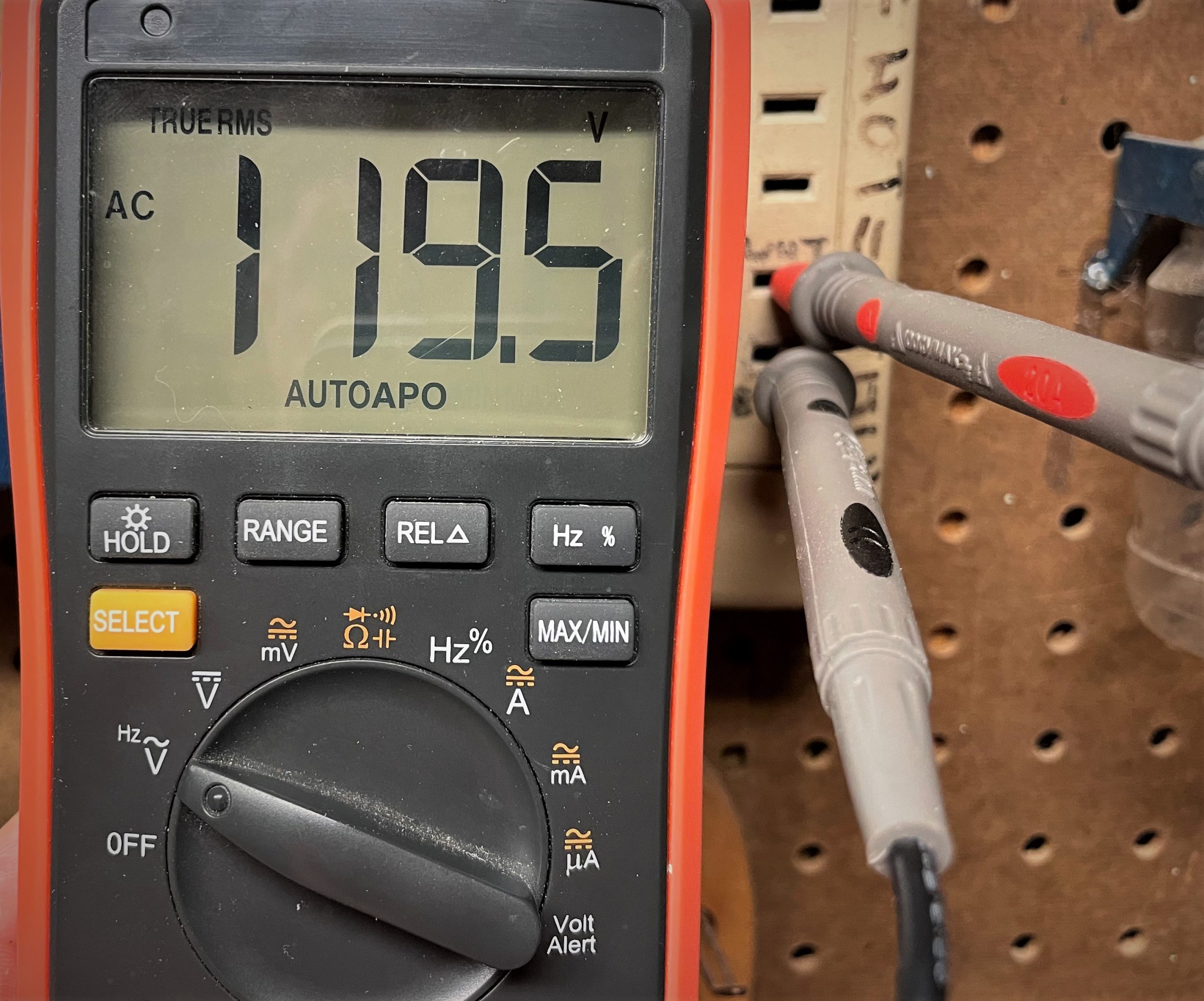
Generally speaking, a vehicle automotive system uses low-voltage DC power. (Fun fact, while most folks colloquially say 12 volts, when the vehicle is running, its charging voltage is actually closer to 13.8 volts DC.) Without going into a full-blown electronics lesson, DC stands for “direct current” and is what comes out of a battery. Conversely, your home uses what’s known as “alternating current” or AC.
While we could spend a few hundred words explaining the distinction, the basic difference between AC and DC is that DC power is polarized, which is a fancy way of saying it requires a positive (AKA: red, “hot,” or +) terminal and a negative (AKA: black, “ground,” or -) connection. On the other hand, for the alternating current in your home, there is no positive or negative polarity to worry about (again, generally speaking). In other words, you can flip around the plug on your kitchen’s waffle maker and it’ll still work fine.
For most automobiles you’ll come across nowadays, the negative connection occurs at the vehicle chassis, often called chassis ground. So, say, for a typical light socket, the negative connection comes via the way it physically bolts to the vehicle frame or body, and there’s a single wire entering the bulb socket itself to provide the positive side connection.
To check for DC voltage, click the big multimeter knob over to the DC Voltage symbol, which looks like a solid line with a dotted line underneath (⎓), though on some multimeters it may be simply abbreviated as something like VDC for “Volts DC.”

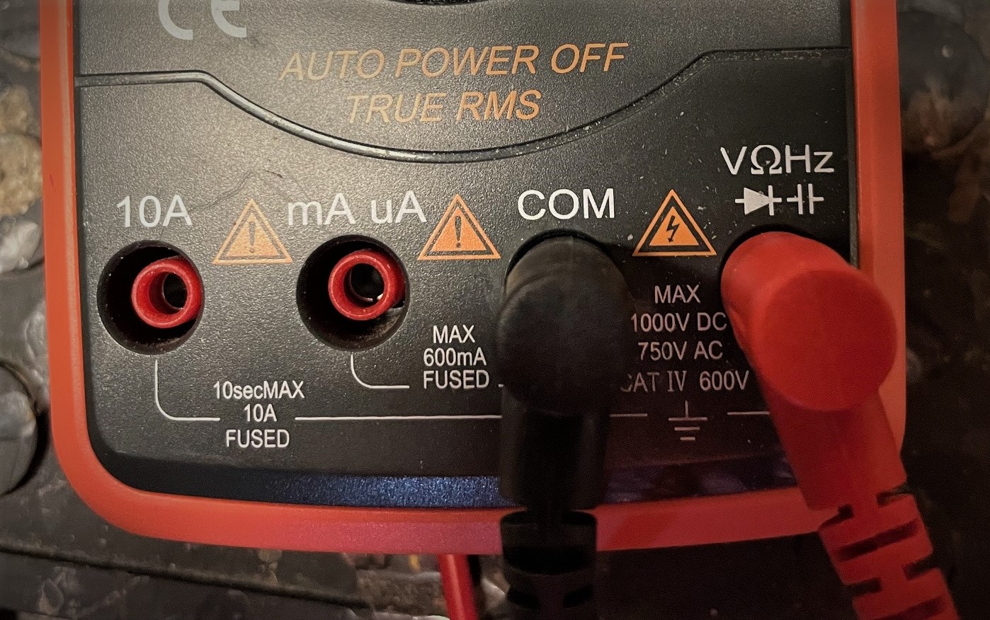
Then you place the black probe on the multimeter to wherever you expect the chassis ground, or the negative ( — ) connection, to be. (Here’s where an alligator clip or test lead is particularly helpful.) Then, attach the red probe to the positive (+) side of the circuit. If the circuit is energized, then you should see the voltage reading pop up on the digital multimeter display.
If you don’t get a reading, double check your connections on the probes. Then, check your battery/power supply. If you still don’t get a reading, then you could have a break in continuity, with either the positive or negative side of the battery. Switch over to your continuity setting we talked about in point one above, and start sniffing out where the break in your electrical power circuit is.
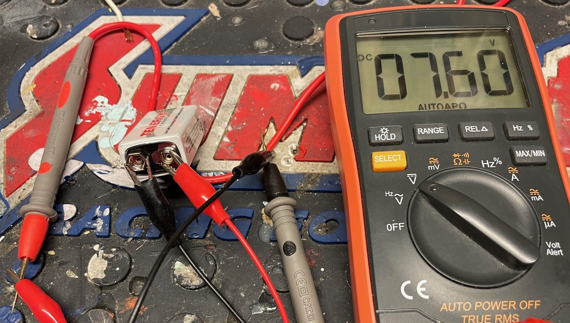
If you’re getting an abnormally low reading, say five volts instead of the expected 13.8, then it could point to a weak or discharged battery. Or it could be resistance in the circuit caused by a loose/weak connection, corrosion, torn wire, or some other damage.
For that, it’s good to know that a multimeter can help measure electrical resistance too…
***
3. Checking & Measuring Electrical Resistance
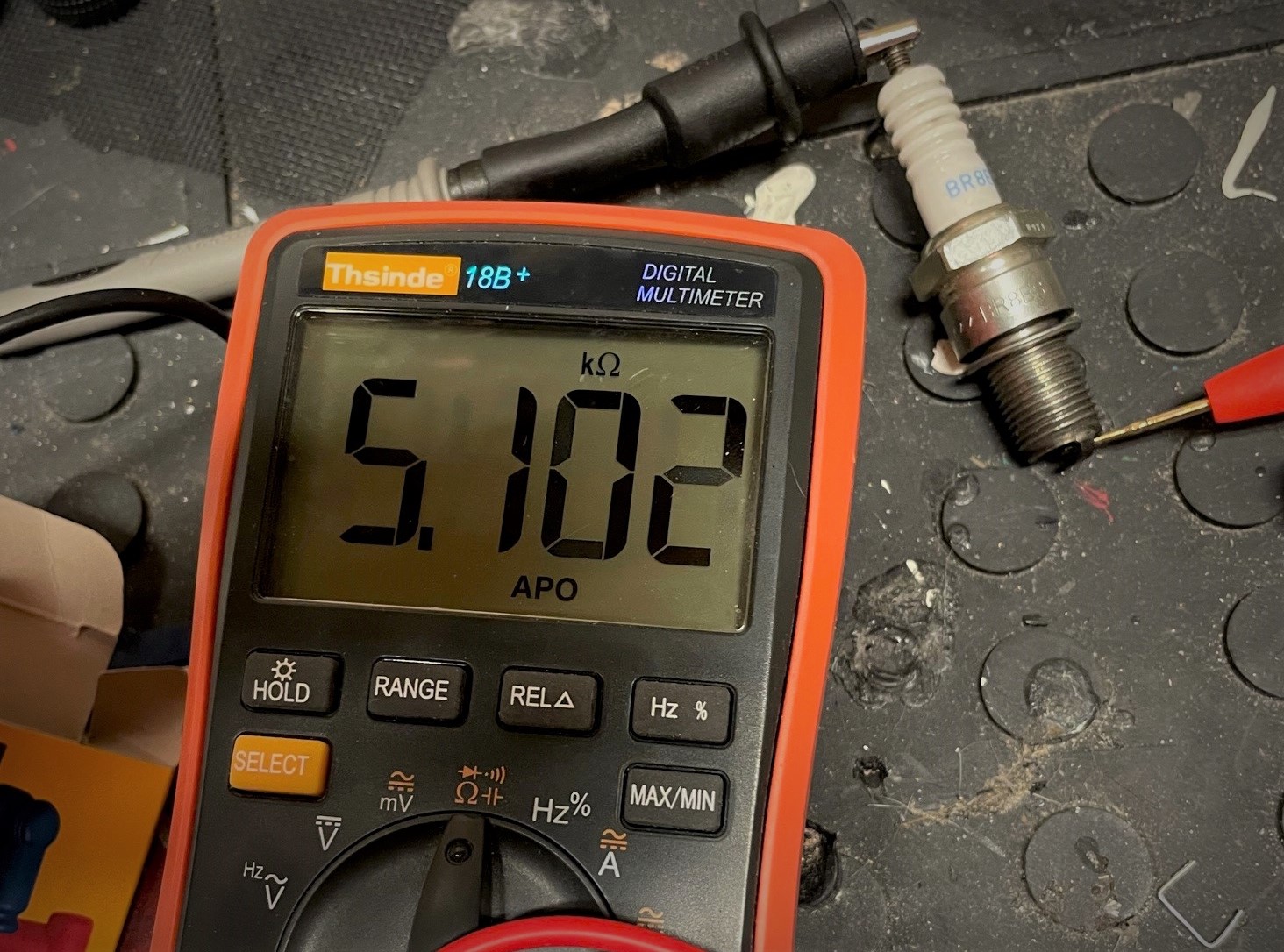
Without going into a dissertation on topics like Ohm’s Law, resistance (or a partial block in the flow of electricity) is a fundamental element of many electrical systems—and that’s true in the automotive world too. (Spark plugs are often a good example of the role resistance plays in an electrical circuit.)
Knowing how to measure resistance with a multimeter is a tad more complex than the other two points above, but still relatively easy once you get the basics down.
For starters, it’s important to understand that there’s a massive range of resistance values, abbreviated by the omega symbol, and it extends pretty much from one microohm (1µΩ or 0.000001 Ω) to one million ohms (called a megaohm, abbreviated as MΩ). That means you might* have to select the proper range on your multimeter to make an effective measurement.
* We say “might” there, because some multimeters have auto-ranging feature—which if were being honest, comes in really, really handy.
Measuring ohms is often a vital part of troubleshooting an ignition system, HVAC system, or really any circuit more complex that a simple light bulb. For example, we diagnosed a bad blower motor resistor with help from a multimeter.

To use a multimeter to check electrical resistance, first click the big knob over the the Ohms symbol. Then you’ve got to determine what range setting you should use—unless you’ve got an auto-ranging multimeter, that is.
There are a few ways to figure out which range to use. Sometimes you’re lucky enough to already know what resistance range to expect, so you can calibrate your multimeter accordingly.
Or, if you’re testing a specific resistor, they’re often labeled with a universal color code that, if you know how to decipher it, then you know what to expect. Here’s a good resistor color code infographic to help you out:
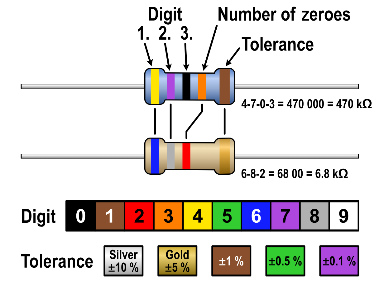
But if you don’t have a good starting range, we typically set our multimeter to kiloohms (kΩ) and then range up or down as needed when we take our readings. Depending on your multimeter model, selecting the range is usually a matter of pressing a button, but it might be a separate switch or knob position too.
As for setting the right range, it’s often a simple matter of conversions.
For instance, if we’re getting a 0.00347 kΩ reading, then we can move the range up so it displays 3.47 Ω. That’s a handy move, because it might allow for more precision on the scale too, like 3.47689 Ω. (There are plenty of online calculators to help you with your conversions.)
When it comes to the actual process of checking resistance, you simply set your ohm range (if needed), and then clip a probe to either side of the circuit you’re testing. Done right, the resistance value should display on your multimeter’s screen.
So on a blower motor resistor for example, we put a clip on the common pin on the terminal plug, then another clip on one of the other terminal pins (blower motor resistors are actually a multiple resistors packed into a single unit, sharing a single common starting point in the circuit).
Just be sure there are no alternate electrical paths “around” the resistor that could affect resistance readings. Electricity is sneaky and will always try to find the easiest path through the circuit.
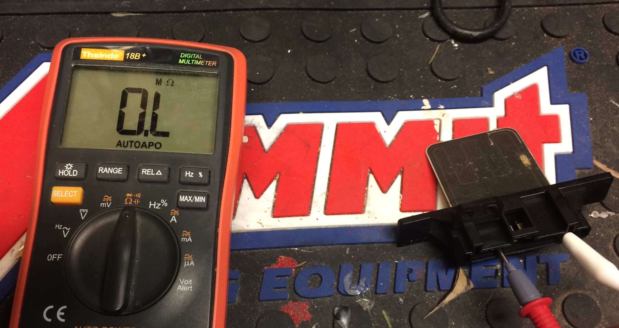
Checking for Continuity Via Zero Resistance
Now, remember when we said there was an alternative way to check electrical continuity if your multimeter doesn’t have that audible beep feature? Well, the workaround is easy. Simply check for zero resistance instead. Think about it: If the connection is solid and sound, then there should be zero (or at least negligible) resistance along the electrical path. So regardless of what resistance range you’re using, if you see a zero reading on the screen, then you’ve got good continuity in the circuit, make sense?
***
This is only the beginning—master these tests and, as Obi-Wan famously said, “You’ve taken your first steps into a larger world.”
That’s because electrical multimeters have a ton of other handy capabilities, like testing diodes and measuring current (amps). More importantly, once you figure out how to use these features, you’ll find a multimeter is an invaluable tool both inside and outside of the garage—capable of troubleshooting both spark plugs and spin cycles with relative ease.
There are ample tutorials out there, but if there’s a specific multimeter function that you’d like us to elaborate on, drop us a note in the comments section below.
Comments