For modern performance enthusiasts, there’s a lot to learn when it comes to making horsepower with turbochargers. The big push in today’s world is the ease with which horsepower can be produced when tied in with boost pressure generated from a small, exhaust-driven centrifugal supercharger. The idea is to use exhaust gas energy, both the pressure and the heat, to drive a turbine wheel tied to a shaft that then turns an inlet side compressor wheel.
Yet while hotrodders and racers have been building supercharged engines since probably two days after the first normally aspirated engine started making noise, turbochargers are a relative newcomer.
Early exhaust gas driven compressors first became popular in the 1960s but they were crude devices that performed more like light switches, generating a reputation for making great power but were also difficult to control and suffered from reliability issues. Today’s turbo engineers have created a wealth of devices that, depending upon your goals, have the potential to make more power than you could possibly use.
But these advancements have also bought along complexity. Engineers are famous for turning what might seem complex problems into easy solutions, but they’re also known for adding nomenclature to our language that can be sometimes confusing.
This article may help too: Forced Induction 101: What’s the Difference Between a Turbocharger & Supercharger
Summit Racing has recently introduced a line of turbochargers that offer a wealth of opportunities to make horsepower. But to those with little hands-on knowledge of these wondrous devices, the first step should be to become familiar with the terminology.
This will require some definitions—and that’s where this story begins.
We will help you navigate this sometimes nonsensical sea of turbocharger terms with the intent that, by the end, you will recognize the terms and be able to speak with some semblance of authority that you at least understand the language. But be forewarned, this is just the first step. Beyond knowing the vocabulary, you will need to then learn how to apply this newfound knowledge in terms of choosing the right turbocharger for your application.
But first, you’ll need to learn the language so you too can speak fluent turbo.
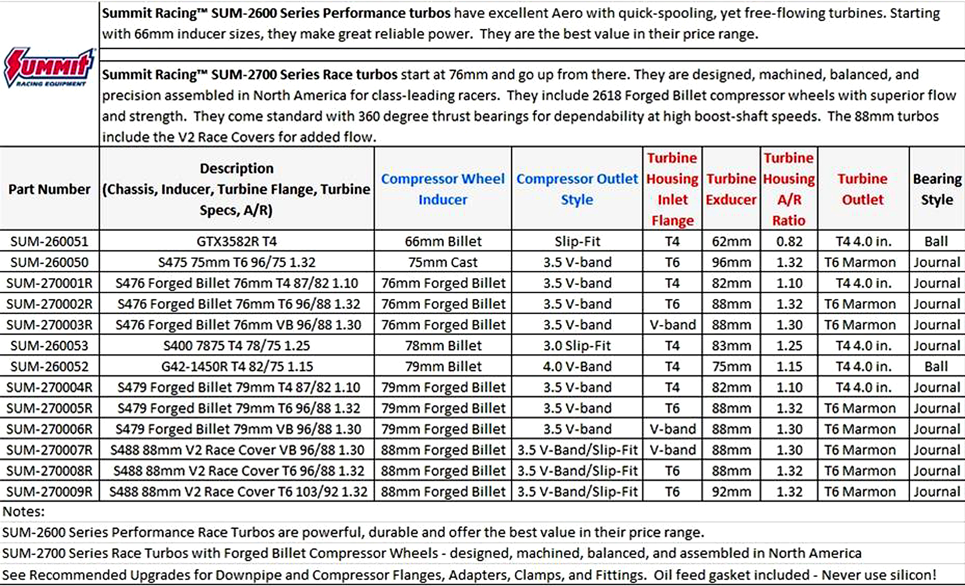
The Summit Racing lineup of turbochargers is delineated into two separate categories. The entry level 2600 Performance Series (SUM-2600xx) is more affordable intended for hot street operation that, with one of the larger units, is still capable of producing north of 1,000 wheel horsepower.
The second level is the 2700 Race Series (SUM-2700xx) that employs forged 2618 alloy billet impellers that are designed, machined, and assembled in North America.
As turbochargers become more application specific, knowledgeable tuners will move into the world of custom-built turbos that are highly specific. But for the entry level enthusiast, these pre-assembled turbochargers are packaged as popular combinations for a street or mild race application.
The terms that we will be defining in this story are the ones most often used to describe a specific turbocharger. These mainly have to do with the actual construction of the turbo and what differentiates the hundreds of different designs. We will use the Summit Racing lineup of turbos to help with these descriptions—but these are also universal terms that apply to all turbochargers. Let’s get started.
***
Common Turbocharging Terms & Definitions
***
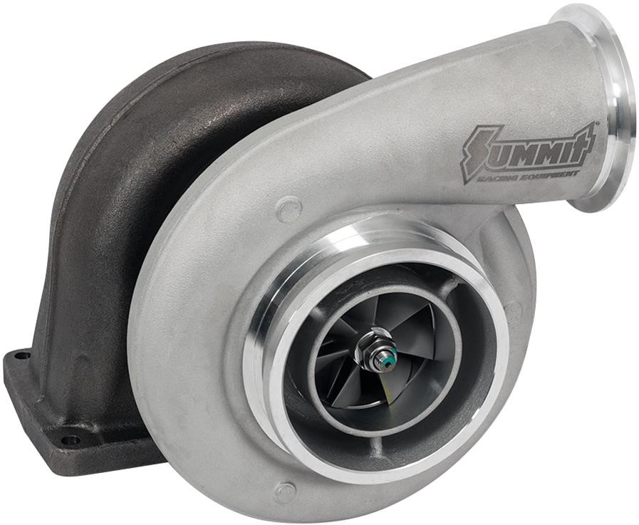
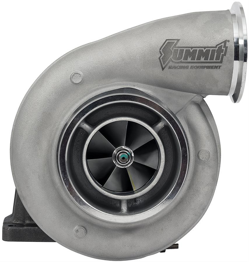
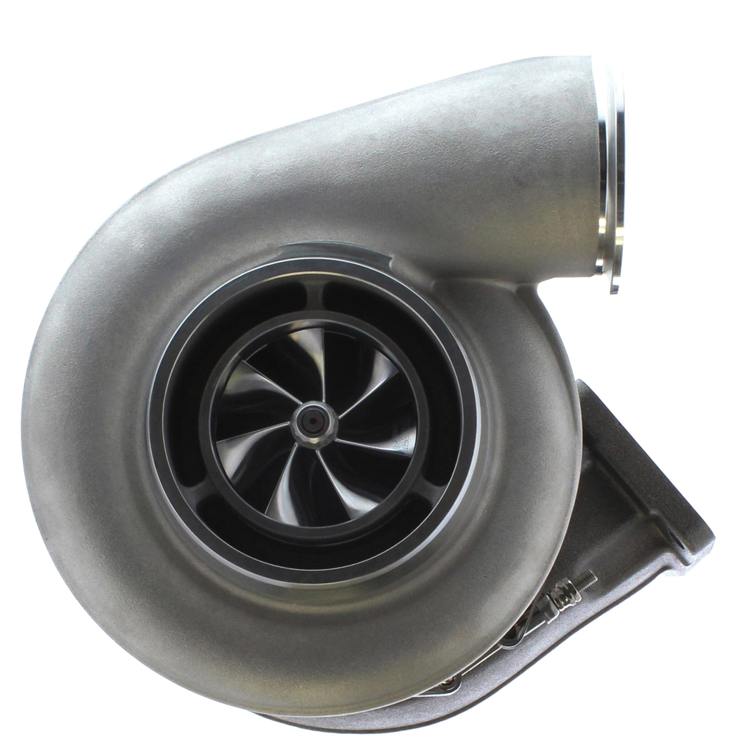
Compressor Section
The compressor wheel can be considered the heart of a turbocharger. The inlet air enters the center of the compressor section and is centrifugally accelerated by the compressor wheel to exit the aluminum scroll which is sized to match the compressor wheel. The wheel is accelerated by the turbine wheel which is driven by exhaust gas heat and pressure, and is connected to the compressor wheel on a shaft supported by a bushing or bearing. There are hundreds if not thousands of compressor wheel designs and sizes that offer specific performance enhancements.
***
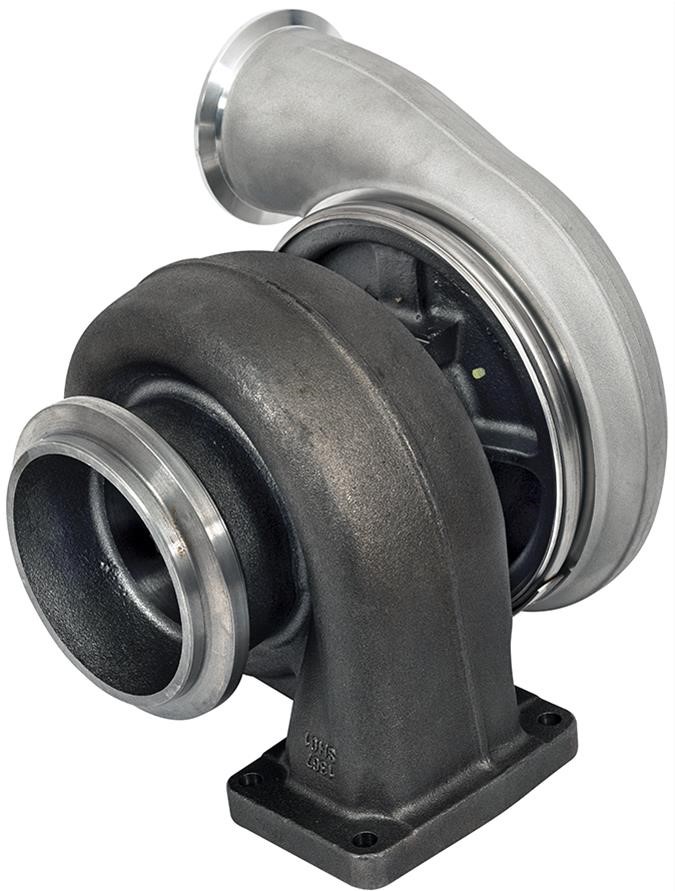
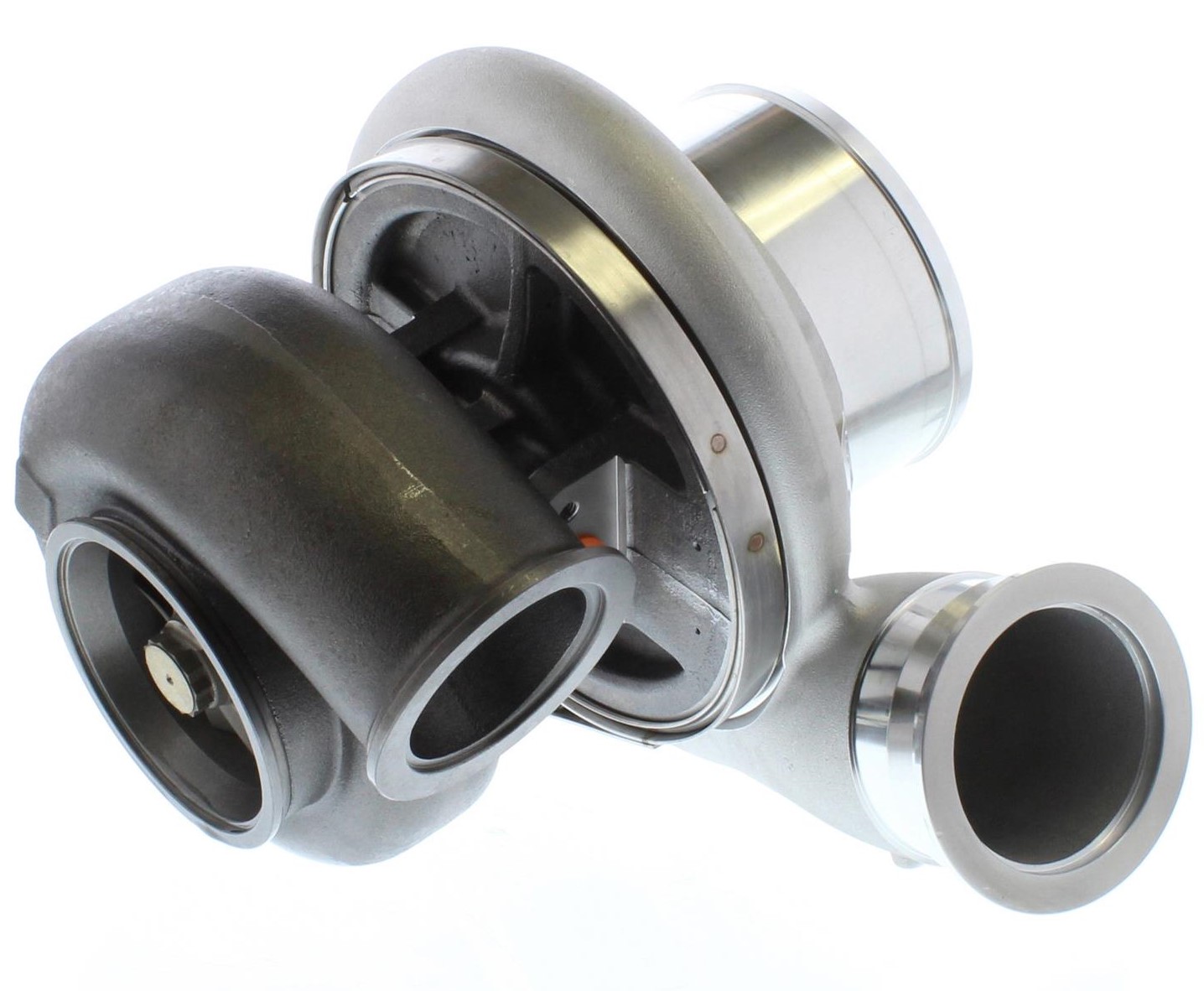
Turbine Section
This is the exhaust or hot side of the turbocharger. The housing is most often constructed of iron necessary for durability. This section houses the turbine wheel that is driven by exhaust gas heat and pressure. The exhaust turbine drives a shaft that connects to the compressor side of the turbocharger. This shaft is sealed and is cooled and lubricated most often by pressurized engine oil that is circulated back to the engine.
***
Compressor Wheel Construction
The compressor wheel is almost always made of aluminum but is offered under several different strength levels. Entry level and most inexpensive turbos use a cast aluminum wheel that is the lowest level in strength rating. It’s important to look closely at some “billet” compressor wheels that are machined but still start out as cast units. They look good but are no stronger than a cast aluminum wheel. Next is a forged aluminum alloy that is fairly common and significantly stronger than cast. The highest level would a forged billet aluminum wheel that offers a substantial strength increase (and also design freedom).
***
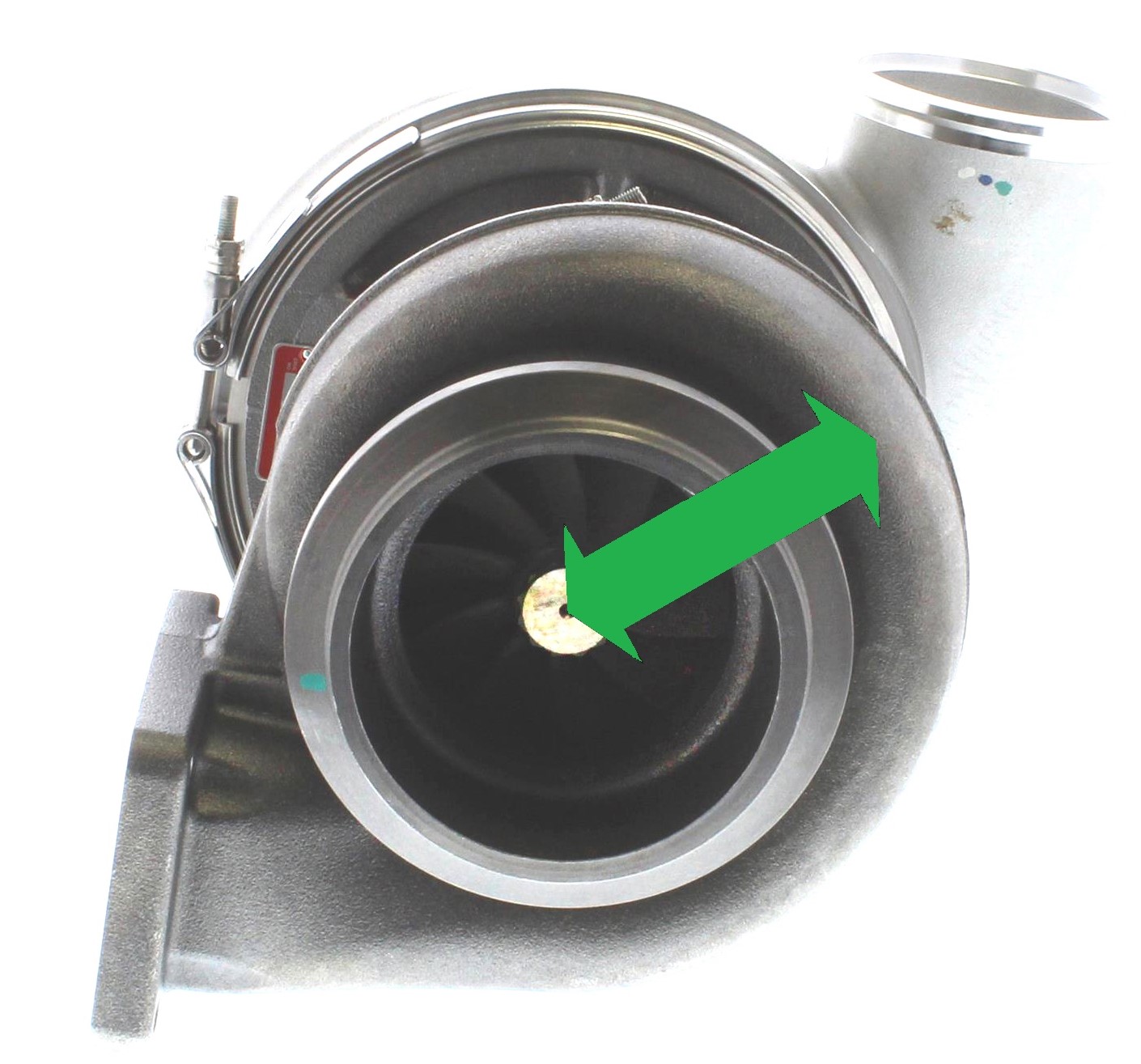
Compressor Wheel Inducer Size
If you look closely at a compressor wheel, you’ll notice that the pinwheel shape begins with a smaller diameter nearest the turbo shaft. This is the inlet side of the compressor wheel and is called the compressor wheel inducer size. This is related to the larger diameter of the wheel called the exducer or exit side. As an example, Summit Racing turbochargers offer compressor wheel inducer sizes ranging from 66mm up to 88mm.
***
Compressor Wheel Exducer Size
The compressor exducer diameter is the larger of the two sizes and is the exit side of the compressor wheel. A given exducer diameter establishes a size proportion between the inducer and exducer that will be more fully explained with the definition of trim sizing coming up under the “turbine wheel exducer” entry. A larger diameter exducer, will move more air at a higher shaft speed compared to a smaller exducer, but is then limited in how quickly it can come up to speed.
***
Turbine Wheel Inducer
The turbine wheel is the exhaust or hot side of the turbocharger that uses exhaust gas pressure and temperature to spin inside the turbine housing. The inducer on the hot side has a larger diameter because it is the portion of the wheel first exposed to incoming exhaust gas in the turbine housing. This larger diameter uses leverage to spin the shaft attached to the compressor side.
***
Turbine Wheel Exducer
This is the smaller diameter portion of the turbine wheel and is the exit side of the exhaust portion of the turbine section. This diameter compared to the inducer diameter establishes the turbine wheel trim number.
***
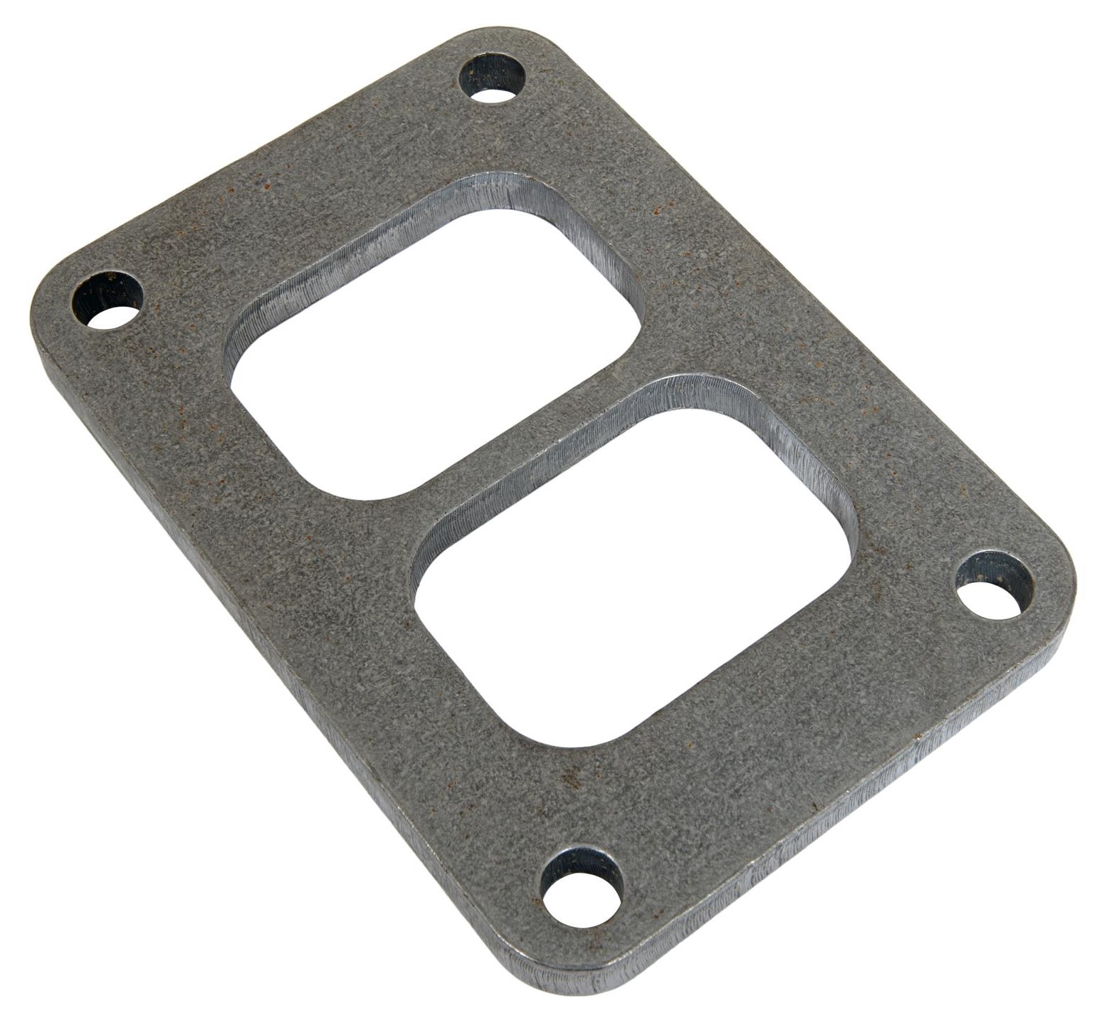
Turbine Housing Inlet Flange
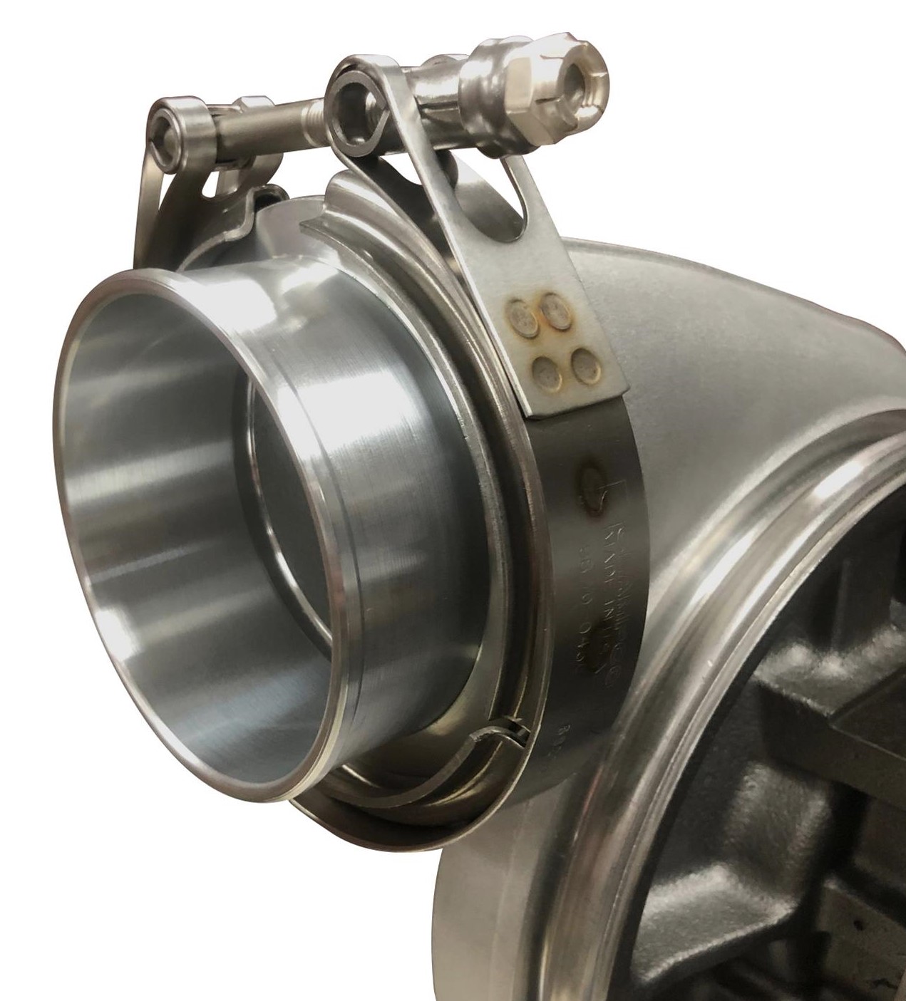
This is where the turbine housing attaches to an exhaust flange coming from the engine. Early turbochargers established standardized mounting flange sizes called out as T-series from T2 through T6. The most common automotive performance turbo flanges are the T4 and T6 with the larger number specifying the larger flange. Larger, high output applications such as Summit Racing’s 88mm turbo use a V-band flange.
***
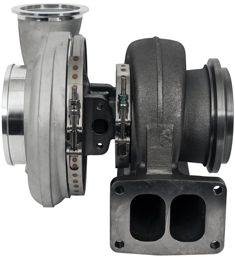
Turbine Housing Scroll – Single vs Dual
Turbine housings are offered in either a single or dual scroll configuration. A single scroll is the more common design with a single large cavity that directs the exhaust gas into the turbine housing. To enhance exhaust gas speed, some turbine housings are fitted with a dual scroll design using a divider wall to split the housing into two smaller cavities that are used to increase low-speed exhaust gas velocity to enhance low-rpm performance of the turbocharger.
***
Turbine Housing A/R (Area/Radius)
This term is used to define the turbine housing’s Area/Radius (A/R) relationship. Each turbine (and compressor) housing will have a specific A/R. This is defined as the area of the discharge tube on the turbine housing divided by the radius of the scroll which is the distance from the center of the housing outward to the center of where the area is measured.
The turbine A/R directly affects how the turbo responds. A small A/R increases the exhaust velocity to spool the wheel more quickly. Unfortunately, this small area will tend to increase turbo backpressure at higher engine speeds, leading to lost performance at these higher speeds. Conversely, a larger A/R will tend to spool up more slowly but is more efficient at higher engine speeds while reducing the buildup of exhaust gas backpressure. You may be able to see from this short description that choosing a turbine A/R is a rather crucial point in determining which combination of A/R housing and related other components will have on performance.
To emphasize this point, the Summit Racing collection of turbochargers span a rather wide A/R range of between 0.82:1 and 1.32:1 with a total of six housing sizes to choose from.
***
Compressor Housing A/R (Area/Radius)
Much like the turbine housing A/R, the compressor housing area is divided by the radius distance from the center of the turbo housing to the center of where the area is measured. Because compressor housings are far less sensitive to changes in A/R, as a result there are fewer options for these applications but it is still important to know that there are A/R ratios available. For the Summit Racing turbo line, there are two options of 0.70 and 0.85. Often, only one compressor A/R housing will be available for pre-assembled turbochargers.
***
Turbo Bearing Style
There are two styles of bearings. The most common and least expensive is a journal bearing much like a main bearing in an engine. Higher end turbos that are expected to respond quickly to throttle changes use ball bearings. Both bearing and journals require engine oil, for both lubrication and cooling requirements.
Even though the Summit Racing 2700 series turbos are bushing turbos, they feature a 360 degree thrust bushing that can take much more thrust loading than 270 degree bearings found on competing models.
***
Wastegate
Many factory or OEM turbochargers come with what is called an integrated or internal wastegate while nearly all aftermarket performance turbochargers use an external wastegate. This device is used to bleed off or dump exhaust gas pressure entering the hot side of the turbo in order to maintain a given boost pressure level. This is generally achieved using a valve located near the entrance to the turbine side. By opening the wastegate, less pressure is fed to the turbine side, controlling boost on the compressor side.
There are generally two styles of wastegates—either a simple diaphragm style that is somewhat failure prone, or the more robust piston style. The 2700 series is a piston style and is used when failure at the track is not an option. Although primarily used in automotive drag racing, it’s rugged enough for brutal diesel tractor competition at up to 150 psi of dome pressure.
***
You may also enjoy this article: Wastegates vs. Blow-Off Valves…What’s the Difference?
***
Exhaust Backpressure
This is more of a performance related term that refers to how efficiently the exhaust side of the turbocharger is sized relative to turbocharger boost. Exhaust gas backpressure is the pressure that exists between the exhaust valves in the engine and the entry point into the turbine side of the turbocharger. This can be easily measured with a pressure gauge tapped into the exhaust pipe leading to the turbine or hot side of the turbo. A higher exhaust side backpressure number means the turbo system is less efficient at making boost.
To evaluate how well the exhaust side is operating, backpressure is most commonly compared to the amount of boost pressure created on the cold or compressor side of the turbo. Comparing these two pressure numbers creates what is called a pressure ratio.
As an example, if the exhaust side measures 50 psi while the compressor side makes 25 psi of boost, this creates a 2:1 pressure ratio. The ideal ratio is 1:1 where the boost and backpressure numbers are the same but this is often difficult to achieve. Generally, a less restrictive turbine side of the turbo will improve the pressure ratio numbers and move them closer to the ideal 1:1 ratio.
***
Blow-Off Valve
A blow-off valve is a similar gate style valve often controlled by spring pressure. Its function is to prevent a pressure from building up on the inlet side of the turbocharger that could damage the compressor wheel. The blow-off valve uses a diaphragm housing located on the inlet side of the turbocharger between the air cleaner and the compressor wheel on the turbo. The diaphragm uses a vacuum hose from the inlet manifold to the diaphragm.
When the throttle is instantly closed from wide-open-throttle (WOT), this manifold vacuum pulls open the blow-off valve and releases pressure pushing on the inlet side of the turbocharger that has now slowed down. If a blow-off valve is not used, pressure buildup on the compressor side can cause what is called compressor surge, which can (and does) cause significant turbo compressor wheel damage. Excessive pressure can also burst cold-side pipes, clamps, and couplers and create hard-to-find boost-leak issues.
***
Summit Racing Turbo Flange Mounting Dimensions
| Flange Type | Part Number | Length | Width | Thickness |
|---|---|---|---|---|
| T4 | SUM-680502 | 3.250” | 2.750” | 3/8” |
| T6 | SUM-680503 | 4.500” | 2.750” | 3/8” |
Comments