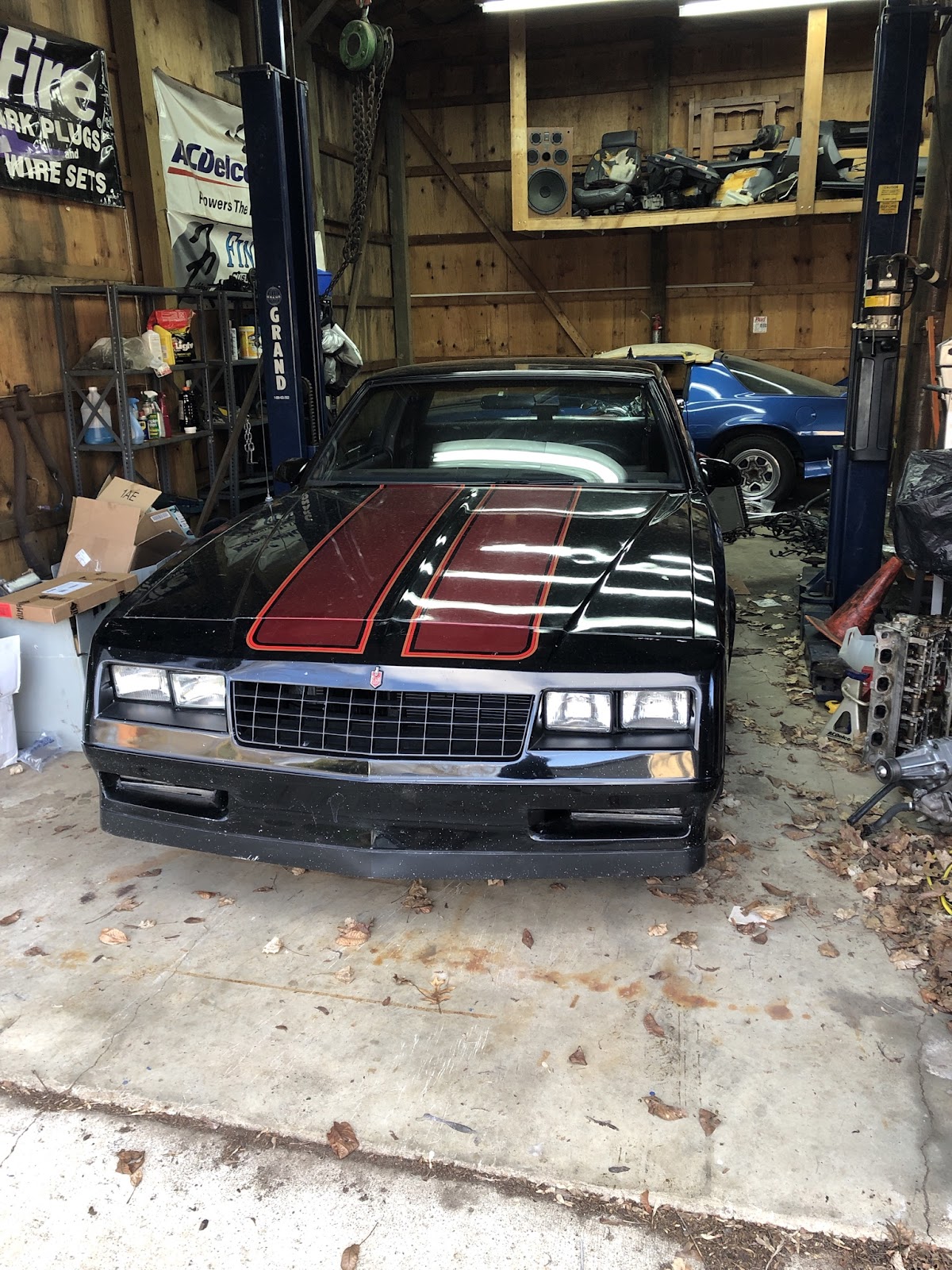
Editor’s Note: Perhaps the only things Travis Jones loves more than his 1986 Monte Carlo SS are autocross courses and a good challenge. That’s why Travis is on a mission to transform his Monte Carlo from an underpowered, ill-handling daily driver to an Autocross hero. A self-described “GM guy through-and-through,” Travis is a regular on the site OppositeLock, has documented his project on his Instagram page (@sslow6.0), and will give us a first-person account of his build here as a guest writer.
Travis has owned the Monte Carlo since high school. Although he’s thought about selling it from time-to-time, Travis has held on to it for sentimental reasons, even though the car has often sat idle. After his girlfriend inspired him to try Autocross for the first time, Travis started to look at the Monte in a whole different way.
“I became obsessed with taking a 1980s boat and making it handle,” Travis said.
In Part 8 of his Monte Makeover series, Jones takes us step by step through the transmission swap.
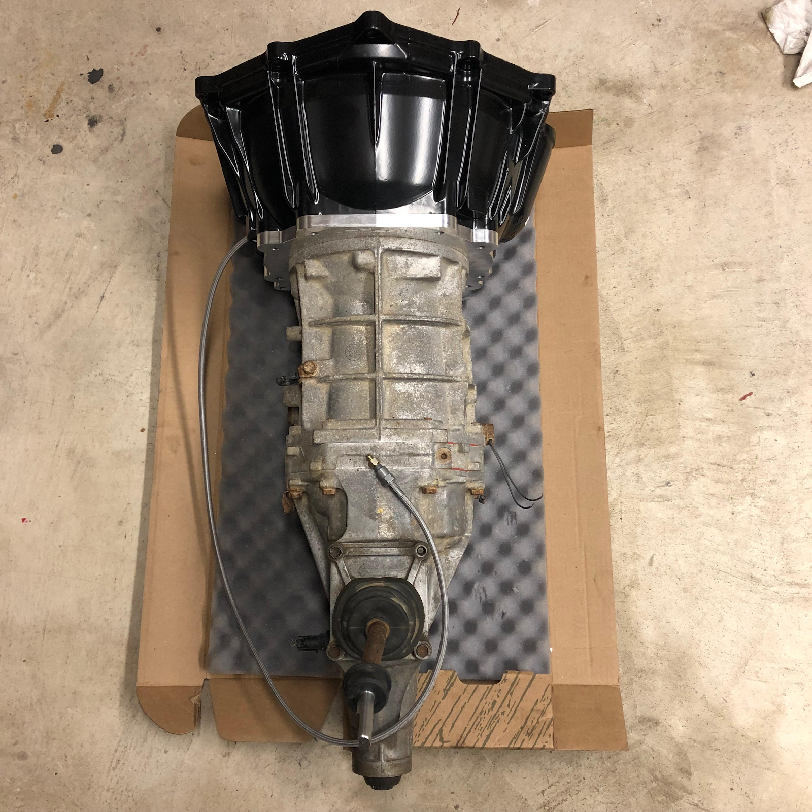
Here’s the AR5 with the FABbot Adapter plate, bellhousing and Tick Performance Speed Bleeder installed. Install the adapter plate to the trans torquing the bolts to 40 ft./lbs. and install the bellhousing to the plate by torquing the bolts to 38 ft./lbs. (Image/Travis Jones)To start, I decided to remove the seats, center console, the sill panels, kick panels and carpet. I wanted to have as much room as possible to get at the brake pedal assembly given the cramped quarters. I also needed to remove the B+M Megashifter, shifter cable, and re-configure my reverse lights and neutral safety switch for the new transmission. Unfortunately when I pulled the carpet out, I found what every hotrodder dreads. The Red Rust Cancer. I knew the driver footwell was a little thin, but I didn’t realize it was this bad. I’ll be buying a patch panel and fixing this at a later date. I tossed a heavy rubber floor mat over the Fred Flintstone portion of the floor, and got to work on the pedals. (Image/Travis Jones) Remove the two 15mm bolts that hold your master cylinder to your brake booster and gently pull the master cylinder away from the booster. Next, contort yourself into a pretzel under the dash and remove the pin holding the brake booster clevis on the pedal and the brake light switch. Then remove the four 15mm bolts holding the brake pedal assembly and booster in place. With a little bit of wiggling and finagling the pedal assembly should come out. Be careful not to get hung up on any wires. I apologize for the lack of pictures, but there isn’t a lot of room under the dash to take any. With the brake pedal removed go ahead and trim the pedal to match the clutch pedal. From here install the SickSpeed Monte pedal by removing the stock crossbolt, and replacing it with the longer bolt provided in the kit, install the clutch pedal and torque the bolt down. Now is a good time to replace the brake pedal bushings if you have any side to side movement in your brake pedal. Here’s the finished assembly. (Image/Travis Jones)
Next, remove the brake booster from your vehicle. Be careful not to drop the pin that runs between the booster and your master cylinder.
Then we’ll need to drill the hole for the master cylinder pushrod to come through the firewall. To drill the hole, I used a 1⅜ step drill bit and used every step it had. I drilled mine at about the 11 o’clock position, but 10-10:30 is where it really needs to be so I did some work with a file to make the hole the right size and shape.
Next, assemble the Tilton master cylinder to the SSM bracket, and follow the Tilton instructions on how to mount the remote feed hose. Once the master cylinder is installed to the bracket, take that and the brake booster and reinstall them, making sure the shaft of the master cylinder goes through the hole you drilled.
After that, re-install the pedal set and the four 15mm bolts that hold the booster and pedal set in. Hold off on re-installing the brake pedal so it can be swung out of the way. Take the aluminum hex piece, jam nuts, and rod end provided in the SSM kit and install them to the pushrod and pedal.
Make sure that everything moves free and doesn’t bind through the stroke of the pedal.
Once you’re happy with the pedal adjustment via trial and error, mark the rod end, loosen the jam nut, and remove it to install the Dorman clutch boot over the whole assembly and attach to the firewall. Additionally, I used sound deadening material to cover the base of the boot and the grommets.
Going back under the hood, reattach your master cylinder, and make a bracket for the remote reservoir that attached to the passenger side of your master cylinder, I used a piece of stainless steel I had laying around, and connected the hose provided with the Tilton Master Cylinder Kit. The pedal and master cylinder are now installed.
Once the pedals were installed it was time to start removing the automatic transmission. Depending on your exhaust and crossmember setup, you may or may not have to remove the exhaust, crossmember, or both.
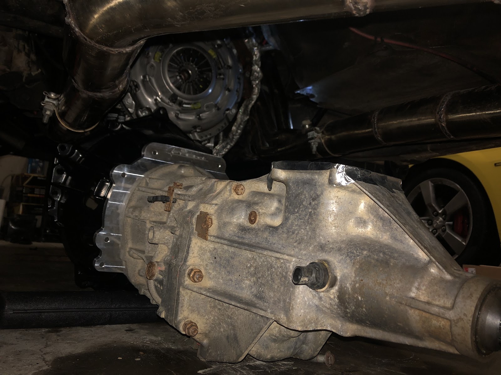
With the Pilot bearing installed I lined up the LS7 flywheel (LUK-LFW191) and installed and torqued it to spec. First pass to 22 ft.-lbs., second pass to 37 ft.-lbs., and the final pass to 74 ft.-lbs. in a “star” pattern. TIP: Do you see the smudges on the flywheel in the picture above? Cleanliness is an absolute requirement when installing your clutch disk. Wash your greasy mitts, spray your flywheel and pressure plate friction surfaces down with brake clean, wipe them down with a clean towel, and keep cleaning them until the towel doesn’t show any dirt or grime. These parts ship covered with rust preventive oil, if you don’t clean them, your clutch disk is going to have a bad time. (Image/Travis Jones)Next, using the clutch installation tool, I hung the clutch and attached the LS7 pressure plate. This time in four passes in a star pattern, first 7 ft.-lbs., 18 ft.-lbs. for the second pass, 30 ft.-lbs. for the third pass, and finally 52 ft.-lbs. for the fourth pass. Tip: The flywheel bolts and pressure plate bolts are not included with the flywheel or clutch kit. The GM part numbers are 12561465 for the pressure plate and 11569956 for the flywheel. You’ll need six of each. (Image/Travis Jones)
With the flywheel, clutch, and pressure plate installed, I decided to mock up the transmission to determine where the shifter would come through.
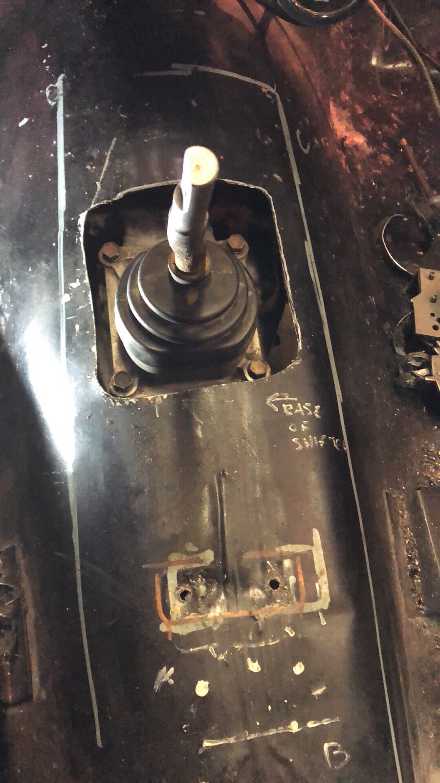
First, I measured from the front of the bellhousing to the rear of the shifter- base attachment point. It was about 25 inches.
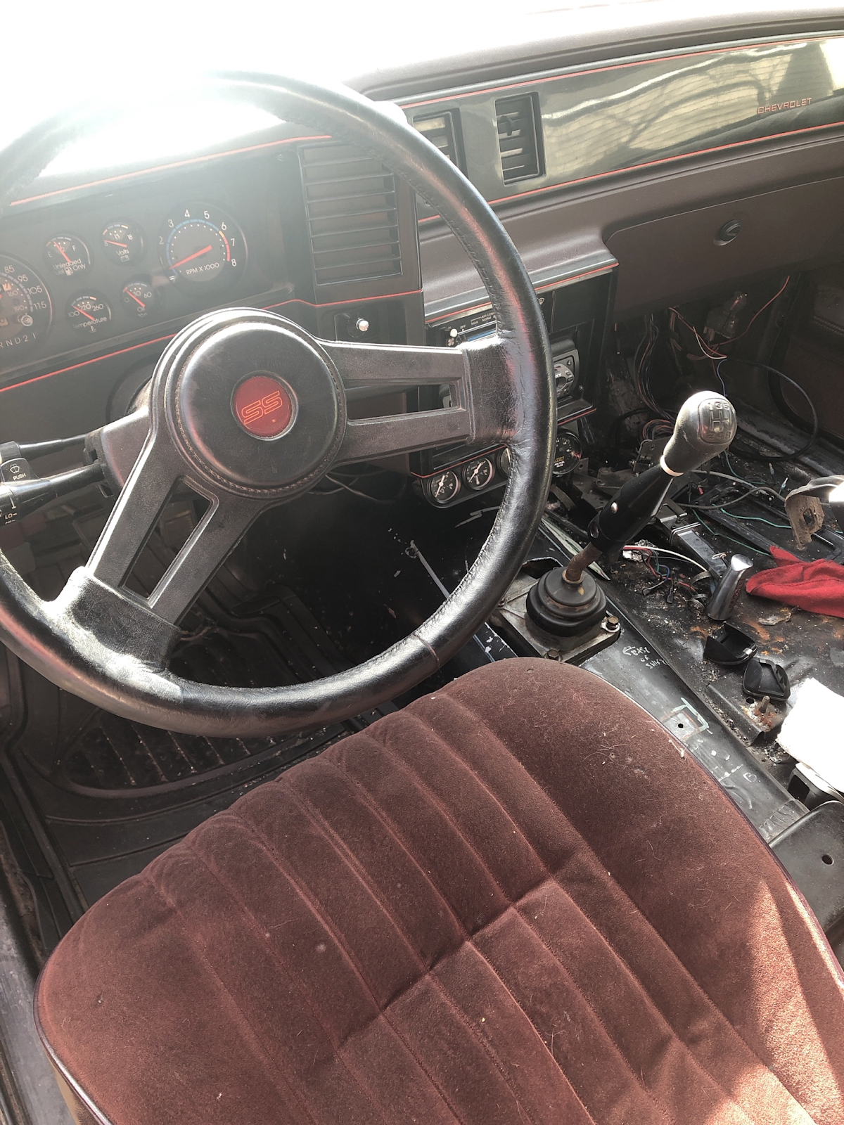
I added a little bit of extra material to account for “build variation” and decided to mark the tunnel at 25.5 inches. From there I made a cardboard template of the shifter mounting surface. I wanted to make sure that I could remove the shifter from the trans in vehicle if I later decided to change shifters. Then I drilled pilot holes at 25.5 inches to find the location from inside the car, and then used the template I made to mark the tunnel and cut the hole.
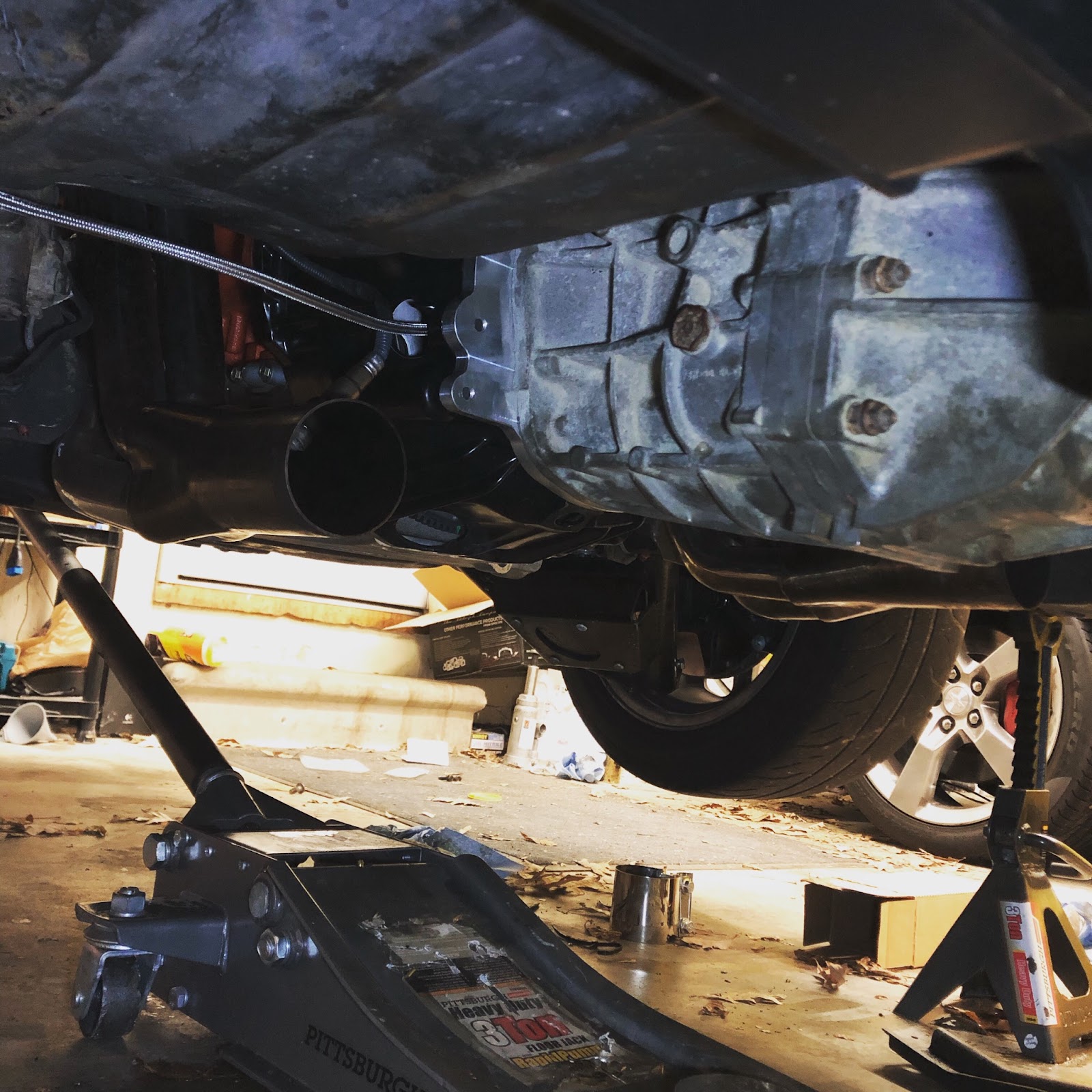
With the hole for the shifter cut, I now had to wrestle the trans into place. Installing a manual like this is a little difficult because so many things have to line up, the input shaft splines into the clutch, the end of the input shaft into the pilot bushing along with the normal things like the bellhousing bolt holes and the engine dowel pins. Additoinally, there is a little bit of spring pressure from the return on the master cylinder that must be overcome. After what seemed like a wrestling match fit for a Pay-Per-View special, I was able to get the transmission in and bolted down. Then I realized that none of my hydraulic lines were installed, and the trans would have to come right back out. “Doh!” TIP: with the FABbot bellhousing, adapter plate, and an AR5 trans make sure your hydraulic lines are attached and solid before you spend two hours wrestling the transmission into place and bolting it down. (Image/Travis Jones)The upside was, I got the transmission tunnel hole mostly right and the shifter position looks pretty good. (Image/Travis Jones)After removing the trans, I was able to install both of the lines and re-install it without issue. For the transmission crossmember, since I had already installed the 12644HKR LS swap crossmember when I did the exhaust, I just needed the Hooker crossmember extension bracket 12655HKR. The AR5 with the FABbot kit has pretty much Identical mounting dimensions as the 1998+ V8 4L60E automatic transmission. (Image/Travis Jones) Next, I measured my driveshaft. I did this after calling my local driveshaft shop and asking how they wanted the measurements. Since I already had the slip yoke, a beefy Dana Spicer unit with provisions for 1350 style U-joints, they told me to push the yoke all the way into the tailshaft as far as it would go, and then measure from the center of the rear pinion yoke to the center of the yolk fully seated into the trans. For my car, it was 49.25 inches. From there they would take about ⅞-inch out of the shaft length to account for driveshaft plunge. I dropped off my slip yoke, and the dimensions to my local driveshaft shop, telling them that I needed a 1350 to GM 3R rear conversion U-joint to interface with my 7.5-inch rear end. They made me a custom three-inch aluminum driveshaft in less than 24 hours! To install the driveshaft, I simply inserted the slip yoke into the trans and then re-installed the rear U-joint straps and bolts, torqued to 35 ft.-lbs. (Image/Travis Jones)Next, since the AR5 was drained of fluid at the LKQ yard, I poured 2.4 quarts of Redline MT-90 RED-50305 into the transmission through the shifter hole. I used some RTV to seal the shifter and torqued down the shifter bolts. I performed a quick function test by firing up the car while on jack stands to check clutch engagement and disengagement, while also making sure the transmission shifted into all the gears. I didn’t even put the rest of the interior back in I was so excited. I put the car back on the pavement and hopped in and fired it up. I drove it gingerly to a secluded, low-traffic two-lane country road with a 55 mph speed limit for a quick test. Going in I knew that the 3.73 ring and pinion set was a little steep for 25.7 inch tires and a manual transmission with a 3.75 first gear so I tried to drive it as gingerly as possible, however at a little more than quarter-throttle, the rear tires were instantly spinning. I tried launching in second gear, with the same results, so I gave up trying to launch the car and tried a 25-55 mph rolling start in second gear. (Image/Travis Jones)In switching to a transmission where I have to shift gears on my own, I transformed this car into an absolute monster. The kind of monster that makes you grin from ear to ear every time you drop the clutch. The driving dynamics of the car are completely different. It has quick throttle response, and the engine seems to rev faster and with more brutality. With the swap complete I’ll patch up the rust hole in the floor, re-install the interior and center console, finish up the wiring, and hit the remaining autocross events this summer. Hopefully the 7.5 inch 10-bolt rear axle lives. If it doesn’t, I’ve got some big plans for the rear axle and suspension in the future. (Image/Travis Jones)
Travis, I would love an update as to how the trans held up over the past year+. You did an excellent job with your write-ups. Thank you for the knowledge you passed down to the rest of us home made hot rodders.
Hi Travis how’s it going going? I have a AR5 transmission and what was the name of the slip yoke? I’ve been trying to find a way to putt a slip yoke in AR5 but idk how.
The Colorado and Canyon AR5 have a slip yoke – not sure about the H3. The slip yoke is a common 27 spline. I believe the Slingshot, Sky and Solstice all have a fixed rag joint setup which might cause more difficulties adapting to your driveshaft.


I want to know whats going on with that third gen in the back. Looks like a 91/92 high rise Z28 spoiler?
The Monte is coming along great! Very excited to see it complete.
What is the part number for the slip yoke you’re using?
Hello, where did you get your slip yoke from and how many splines is it?
27 is what the output of the trans requires. It is very standard GM stuff.
I am interested in the 200-4R that was removed from this car. Let me know if it’s available.
Travis, I would love an update as to how the trans held up over the past year+. You did an excellent job with your write-ups. Thank you for the knowledge you passed down to the rest of us home made hot rodders.
Hi Travis how’s it going going? I have a AR5 transmission and what was the name of the slip yoke? I’ve been trying to find a way to putt a slip yoke in AR5 but idk how.
The Colorado and Canyon AR5 have a slip yoke – not sure about the H3. The slip yoke is a common 27 spline. I believe the Slingshot, Sky and Solstice all have a fixed rag joint setup which might cause more difficulties adapting to your driveshaft.
Great writeup. I’m in the middle of doing an AR5 in my 1982 Camaro with a 5.3 and the original T10.
What did you do to hook up the Speedo?