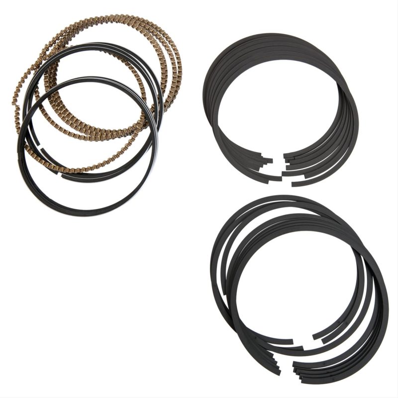
(Image/Summit Racing)
Piston rings are a critical part in any engine.
It’s amazing what they put up with when you really think about it. The top ring provides a near-airtight seal against thousands of degrees of combustion while moving at speeds that can exceed 125 feet per second. Then, we expect them to live for 3500+ hours of operation.
When the Summit Racing Pro LS piston rings were being chosen for the Summit’s Pro LS forged pistons, there were several requirements.
- Made in the USA
- Able to deal with high levels of boost and nitrous
- Exceed factory ring life
- Unmatched seal for power production
- Low friction
- Little to no oil consumption
The 5.7L and 6.0L Pro LS pistons use a nitrided stainless steel top ring and measure 1.2 x 1.2 x 3.0mm.
The 5.3L pistons use a plasma steel moly and measure 1.5 x 1.5 x 3.0mm. The whole LS series offers martensitic ductile second rings along with Flex Vent oil control rings.
1.2mm Stainless Nitride Top Compression Rings
These compression rings utilize an ASL 817 stainless steel for the base material. The use of this material is necessary to successfully perform the nitriding surface treatment.
Nitriding is a thermal treatment used for enhancing the performance of the outside diameter running surface and the sides of compression rings. The stainless steel rings are placed in a treatment chamber that is filled with nitrogen (via ammonia disassociation) which is then absorbed into the surface of the stainless steel to form a multi-phase nitride case layer at the surface regions.
This hardened layer provides a significant increase in hardness as well as excellent wear and scuff resistance. The nitrided case depth on the ring is typically .002” deep on the outside running surface of the ring and .001” on the sides and the inside of the ring. The hardness at the surface will be about 900 HV0.
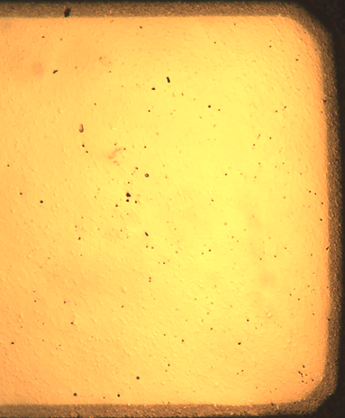
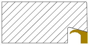
Cross section of Nitride Stainless ring showing the nitride case on the outside.
In addition to the wear properties, the nitrided sides also are more resistant to micro-welding than non-nitrided material. Micro-welding is a phenomenon where material from the piston groove is transferred and “welded” to the ring material.
This will cause damage to the groove and ring while also decreasing performance due to the ring’s inability to move freely. It can ultimately result in the ring becoming stuck in the groove.
The 1.2mm nitride rings have a .145” radial wall which allows for proper back clearances when used with the majority of performance pistons on the market.
The back clearance is the area behind the ring and the bottom of the piston groove. Optimized back clearance is targeted to be in a range of .005”-.030” for the best performance.
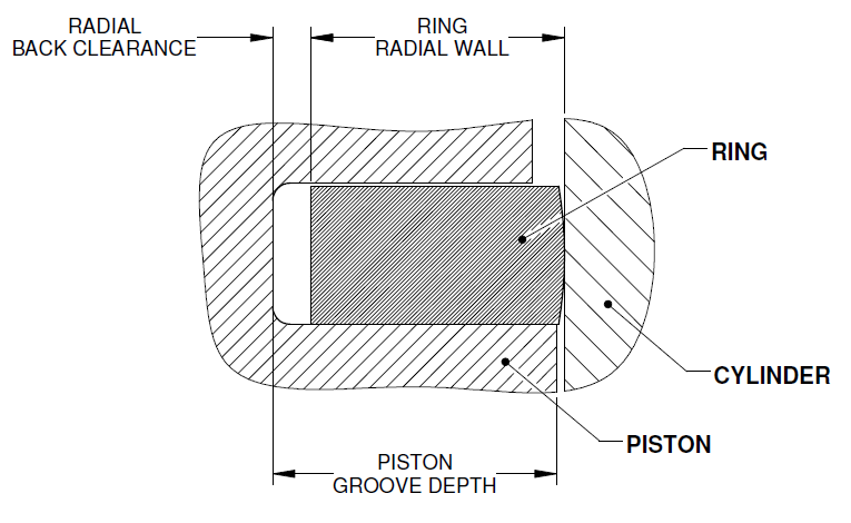
Radial Wall and Back Clearance Measurements
The top rings also utilize a convex or barrel shape on the running surface. A ring will eventually evolve to this shape after running in an engine due to the up-and-down movement of the ring in the piston groove during the upstroke and down stroke.
This shape is beneficial for optimized oil film lubrication and provides better sealing due to a specific contact point on the cylinder. To promote this benefit earlier, the rings at the factory are lapped in a cylinder to obtain this surface shape which will make them uniformly 100-percent “light-tight” which eliminates the need for the rings to be broken-in after engine assembly.
The term light-tight refers to a ring’s ability to conform to the cylinder wall and not allow light to pass through the ring face and the cylinder wall.
All ring manufacturers perform a visual check for the amount of light that passes between the ring and cylinder around the entire circumference with the exception of the gap. Typically, the specification for most rings would be 0-percent light allowed around the circumference, which would be considered a 100-percent light-tight ring.
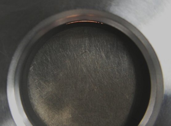
You can see light coming through in upper part of this photo.
The tension of these rings are based on mathematical calculations to ensure proper load on the cylinder wall while balancing proper friction characteristics, wear rates and acceptable internal ring material stresses.
1.5mm Steel with Plasma Applied Molybdenum Top Compression Rings
These compression rings use a SAE9254 alloyed steel (like valve spring steel) for the base material. The use of this material provides many benefits due to the high modulus strength and toughness of steel over conventional grey or ductile cast iron.
The running surface of the rings contain an inlaid plasma applied molybdenum (moly) with nickel- and chromium-enhancing particles in the coating. This coating is applied to the rings by filling a channel in the steel wire with moly using a plasma thermal spraying process.
Moly is a great surface coating due to the highly favorable wear- and scuff-resistance characteristics it provides. Also, the moly coating itself is slight porous which increases the coating’s ability to retain oil for better lubrication. The moly depth on the ring is typically .004”-.007” thick, and the hardness of the moly coating is between 325-500 HV0.5.
The 1.5mm steel moly rings contain the same radial wall and barrel face profile as the 1.2mm stainless nitride rings to provide all of the same benefits. The tension of the 1.5mm moly rings are also designed following the same mathematical calculations to ensure proper load for ring sealing.
Martensitic Ductile Second Compression Rings
The second compression rings offered in the LS performance line are made of spheroidal graphite cast iron which is heat-treated to form a martensitic structure.
The Martensite increases the hardness to withstand wear in high performance LS engines. The ductility and toughness of the base material allows the Napier ring to be twisted without the fear of fracturing the ring.
The 1.2mm axial width Napier rings have a .145” radial wall to fit the performance pistons in the market. The 1.5mm axial width Napier rings have an increased radial wall of .163” to match the deeper grooves of the pistons they were designed for.
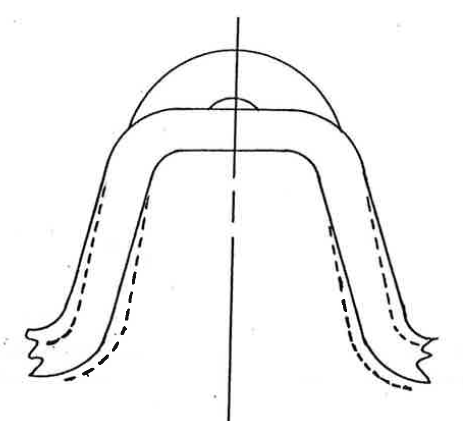
The Napier profile utilized on these compression rings offer many benefits for oil control. The hook groove feature increases the unit pressure providing the force in a more localized area. The step also causes the ring to twist in a positive direction which will bring the ring periphery contact on the cylinder bore at the bottom edge for better oil scraping.
Additionally, the step increases the volume for scraped oil to flow through and acts as a reservoir for stored oil to drain back so as to minimize any upward oil migration past the ring. The undercut feature allows for a sharp edge to be present during ring twist, allowing oil to be removed away from the scraping edge and promoting better scraping ability.
Napier Oil Scraping
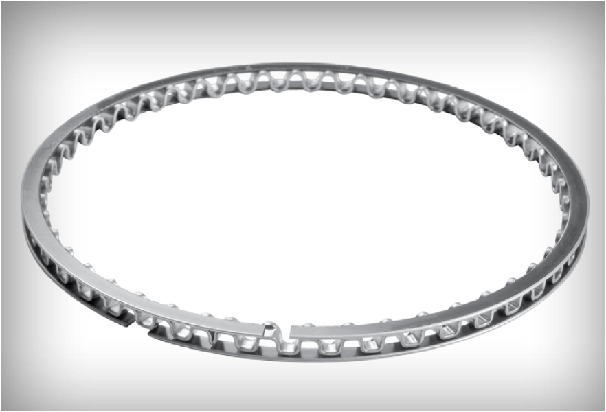
3.0mm Flex Vent Control Rings
The oil control rings utilized in the LS series contain the industry standard Flex Vent design which promotes better oil drainage, improved axial sealing of the rails to the piston groove, and promotes uniform cylinder wall pressure and conformability.
This design contains three pieces with two rails on each side of a flex expander.
The rails are made of SAE 1070 segmented carbon steel and obtain a chrome plating on the outside running surface for added wear resistance. The flex expander is made out of a 201 stainless steel material.
This design contains three pieces with two rails on each side of a flex expander.
The principle function of the Flex Vent assembly is to meter the oil film on the cylinder wall for proper piston lubrication.
To achieve this, the expander supports two rails in the groove while also providing expansive force on the back of the rails to make them scrape oil from the cylinder bore.
The expander is designed with a tab on the inner edge of the expander for the rails to rest against. The expander itself is a very sophisticated spring which when compressed into the cylinder bore will cause the deflection of the expander humps and thus providing the force that acts upon the back of the rails.
Oil ring tension is measured tangentially using an industry accepted method which involves measuring the force needed to close the assembly to cylinder bore size using a band around the assembly.
The Pro LS series rings were designed to be slightly higher than the low-tension oil rings found in the performance market. The tension range is about 13 lbs. while other low tension rings would be about 10 lbs.
The reason for doing this revolves around the engine testing that was done during the development of these new ring sets. Using the 13-lb. oil rings over the 10-lb. oil rings exhibited excellent oil control while keeping friction and horsepower losses minimal.
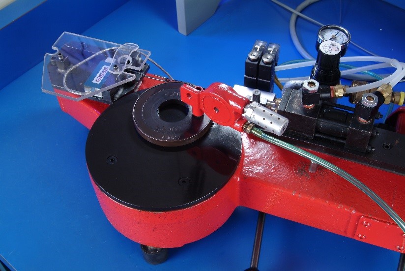
Tangential Tester
(Summit Racing’s Brian Nutter contributed to this article.)
Comments